A Digital Camcorder Image Stabilizer Based on Gray
Coded Bit-plane Block Matching
Yeou-Min Yeh, Sheng-Jyh Wang and Huang-Cheng Chiang
Institute of Electronics Engineering, National Chiao Tung University
Hsinchu, 30010, Taiwan, R.O.C
and
Industrial Technology Research Institute
Hsinchu, 30010, Taiwan, R.O.C
ABSTRACT
In this paper, we proposed an efficient algorithm to do image stabilization for digital camcorder. This approach is based on gray-coded bit-plane block matching to eliminate the unpleasing effect caused by involuntary movement of camera holders.
To improve moving object detection and stabilization performance, a frame is divided into several blocks to do localized
motion estimation. Based on our architecture, the temporal correlation is used at the motion unit to efficiently detect moving objects and panning conditions. To compensate for camera rotation, an energy minimization is also applied to calculate the coefficients of affme transform without many complicated computations. Having considered both programming flexibility
and hardware efficiency, the motion decision and motion compensation units are coded in a microprocessor that
interconnects with the stabilization hardware. The proposed stabilizer is now implemented on FPGA 10K 100. Keywords: Digital image stabilization, Motion estimation, Digital camcorder, Gray-coded bit-plane
1 .INTRODUCTION
In recent years, more and more video cameras are accompanied with compact size and powerful zooming capability. The
advancements of these features make the image stability problem even more crucial, because an unconscious movement of the holding hand may cause an annoying shaking of the images. Consequently, we usually need a digital image stabilization (DIS) system to soothe the problem. A digital image stabilization system using only image processing techniques could be a suitable solution because such a system can be fully realized in VLSI to fit the compactness requirement. Up to now, many approaches regarding digital image stabilization have been proposed and some of them already have been implemented in video cameras.
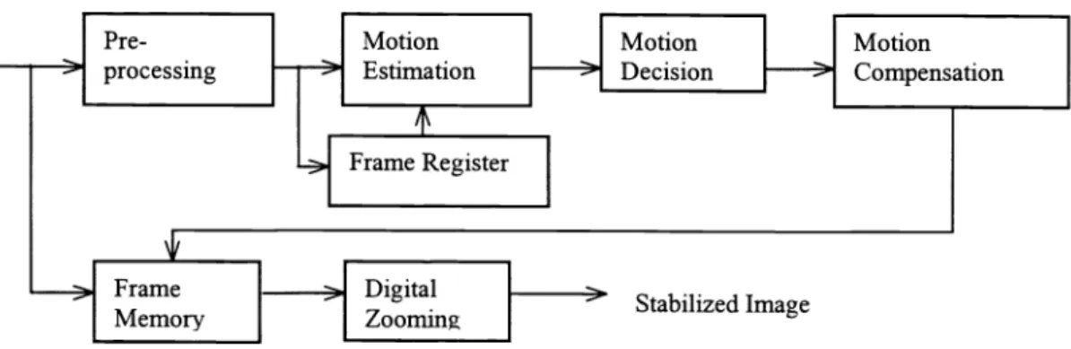
Figure 1 shows a typical structure of a digital video camera with a digital image stabilization (DIS) system and a
corresponding frame memory (FM) [1]. The frame memory is needed to store current image data and to output the stabilized
image data. As shown in Figure 2, a general DIS system usually includes five major components: (1) the pre-processing unit, (2) the motion estimation unit, (3) the motion decision unit, (4) the motion compensation unit for FM, and (5)the
digital zooming unit [3].
CCD
> AID
DIS with FM>
Encoder>
D/AProcessor
A traditional way to do motion estimation is the block matching method [1J[2][3][4][5][6][7]. To reduce computational
complexity, these block matching methods usually divide an image into a small number of blocks and select some
representative points to calculate the motion vector for each block. Then, they use these block motion vectors to estimate the global motion vector to compensate the movement of the whole image. However, the rough division of an image may cause
the loss of local information and the reduction of precision in global motion decision. Without decreasing the accuracy of motion estimation, Sung-Jea Ko and Sung-Hee Lee adopted bit-plane or gray-coded bit-plane block matching to greatly reduce the computational complexity. However, their algorithms are still based on traditional methods for block division,
motion decision and motion compensation [8][9]. For these conventional methods, only simple strategies can be applied in motion decision and motion compensation.
To reserve low computational complexity and the high performance of motion estimation, we also use block-matching
method over gray-coded bit-planes to do motion estimation. However, we divide a frame into several blocks to do localized block matching for improving the detection of moving objects. We design a new approach, which uses temporal correlation to efficiently detect moving objects and panning conditions. In our architecture, both rotational and translational movements
can be compensated. Here, the affme transformation is adopted to align the image contents in different frames. Finally, an
efficient and "real-time" hardware is also implemented.
2.LOCALIZED BLOCK MATCHING OVER GRAY CODED BIT-PLANE
Sung-Jea Ko and etc. [9] proposed the usage of bit-plane images instead of the 8-bit gray level images. With bit-plane images, the block matching process can be implemented using only binary Boolean functions and thus the computational complexity is significantly reduced. In this paper, we also use gray-coded bit-plane images as the basis to do motion estimation. Assume f(x,
y)
is an image and g1(x,y)
are the corresponding gray coded bit-planes.That is, if
f(x,y) =
aKI(x,y)2 +aK2(x,y)2"2 + +a1(x,y)2+a0(x,y) Eq. (1)then
g1 (x, y) =
a. (x, y) a11 (x, y)
0 i K-2 Eq. (2)g1(x,
y) = a_1(x, y)The correlation measure to calculate the motion vectors is defmed as:
1 M—IN—1 Eq.(3) x=Oy=O 113 Digital 1 > StabilizedImage
L..2___J
ZoomingIn Figure 3, we demonstrate the comparison of a traditional rough-division method which is working on 8-bit images. and our fine division method which is working on gray-coded hit-planes. Since the operations over gray-coded bit-planes and much simpler than the operations over 8-bit gray-level images, the computation complexity of our approach is roughly the same as previous approaches even though we have applied a much finer division over the images. The image in Figure 3 is extracted from an image sequence. which is captured by an intentionally shaked video camera. The scene in the image sequence also contains a moving object, which is moving to the right. The traditional rough-division method divides this frame into four blocks and detects four local motion vectors separately: (4,0). (-l.-6). (-5,1). and (-2.2). Three of these 4 motion vectors, except the lower-right block, are not reliable due to either lack of features or the appearance of repeated pattern. The detected motion vector of the lower-right block is also unreliable since this block contains both the motion of a moving object and the motion caused by the shaking camera. Therefore, in this example. the traditional rough-division approach fails to estimate the motion caused by the vibrating camera. On the other hand, with our fine-division approach. many localized motion vectors may still survive and the result is shown in Figure 3(b).
Figure 3 (a) Rough-division of image and the detected motion vectors. (b) Fine-division of image and the detected motion vectors.
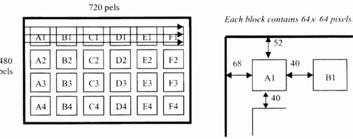
As mentioned before, the complexity of the fine-division motion estimation is about the same as before with the computation of a large block being decomposed into a few computations of smaller blocks. The localization of motion estimation has two advantages. First, the presence of some movmg objects in the image frame will have less impact on the accuracy of motion estimation. Second, the increased amount of motion vectors may increase the signal-to-noise ratio. However, how to choose a proper block size becomes an important issue. If block size is too small, the accuracy of niotion estimation is decreased: while if block size is too large. some local information will get lost. Consequently. for a practical camera system, we choose the block size to be 64 x 64 and we divide each frame into 24 regions. as shown in Figure 4. to meet this trade-off.
720 pels
480 pels
Figure 4. Illustration of the division of the gray-coded bit-planes in our camcorder system.
—
Each block contains 64x 64 pixels.
—. 1
_HD2
To evaluate our approach, we compared the estimated frame motion vectors based on the fine-division over gray-coded bit-plane matching and the conventional method based on the rough-division over 8-bit plane matching. I [crc we utilize the Root-Mean-Square-Error (RMSE) measure to evaluate the performance. RMSE =I means that the average estimation error
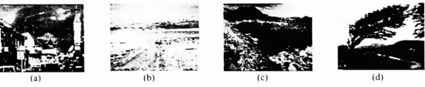
equals to 1 pixel. We consider four test image sequences ((a)—.(d)) as shown in Figure 5 with a resolution of 640 x 480 pixels and 11 frames, which contains simulated hand-shaking motion. The results are display in Table 1. From Table 1(1) and (2). we can observe that the RMSE of our approach is approximate to the conventlimal method and both of them are far smaller than 1. By observing Table 1(3). while the sequences are suffering in AWGN with variance 0.003, the RMSE is still
smaller than one pixel.
(b)
Figure 5. Four test sequences used for evaluate the performance of motion estimation.
Test image Sequence
(I) 8-bit plane (RMSE) (2) hit-plane (RMSE) (3) bit-plane in noise (RMSE) (a) 0.05391 0.06219 0.11879 (b) 0.06883 0.12458 0.20827 (c) 0.06544 0.12647 0.24014 (d) 0.04002 0.06884 0.07864
Table 1. The comparison of RMSE with three different conditions in tour test sequences.
3.MULTI-RESOLUTION BLOCK MATCH1G
To estimate the frame motion vector of kth frame in an image sequence. we define the kth frame as the current frame and the (k- 1 )th frame as the reference frame. For each block in the current frame, we search within a predefincd "scarchmg range" over the reference frame to find the "best" match and thus estimate the localized motion vector of this block. To deal with the possibility of larger movement of hand shaking. a larger searching range is usually needed; however, to reduce the computation complexity, a smaller searching range is preferred. In order to handle the large movement without adding too many computation loads, we adopt a multi-resolution strategy.
With a down-sampling-by-2 multi-resolution structure, the magnitude of the motion vectors in a lower resolution is proximately twice the magnitude of the motion vectors over the corresponding region in the next higher resolution. This phenomenon implies that we may apply the same block matching method over the low-resolution image to estiniatc the motion vectors when the frame motion is out of the searching range in the higher-resolution image. This multi-resolution approach helps in dealing with large movement of hand shaking.
Besides the detection of large movement, multi-resolution also provides some other advantages. The information of motion vectors estimated in lower resolution could be passed to higher resolution frames. Thus, the searching area in the higher resolution can be well localized into a small area. This will lower the computation load. Furthermore, the motion
decision in lower resolution could also be utilized in high resolution. Hence, if we deduce in the lower-resolution layer that a region is lack of texture and its motion vector is unreliable, we may deduce the same conclusion for corresponding region in the higher-resolution layer.
4.DETCTION OF EXISTING MOVING OBJECT AND PANNING CONDITION
There exist many factors that may affect the accuracy and performance of motion estimation, which we call "irregular
conditions". Many methodologies for detecting these conditions have already been proposed. However, these methods may
be very complicated or may not be suitable for our architecture. Consequently, we design our own methodology to detect these conditions for localized block matching over gray coded it-planes. Here, we only concentrate on how we detect
moving object and panning conditions.
4.1. Random Like Motion and Temporally Correlated Motion
If an image sequence contains a moving object, the regions including this moving object may offer incorrect local motion vector. Thus we need to eliminate these invalid local motion vectors to ensure the accuracy of motion compensation. Here, we propose a method that is efficient and can be easily implemented for detecting the existence of moving object. First, we
want to discuss the difference between two kinds of motion: random-like motion and temporally correlated motion. As
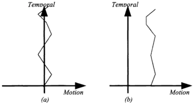
shown in Figure 6(a), a motion regarded as random-like will fluctuate around zero and the variance of this motion will be
relatively large. However, Figure 6(b) shows a temporally correlated motion, which usually moves in a specific direction
and the variance of this motion will be relatively small.
Temv al
(a)
Figure 6. Two kinds of motion: (a) random-like motion (b) temporally correlated motion.
4.2.
Existing Moving Object and Panning Condition
After we have discussed the major difference between random-like motion and temporally correlated motion, we may fmd
that these two types of motion are closely related to the motion caused by hand shaking and the motion caused by
intentional panning. The motion caused by hand shaking makes the captured scene fluctuate around the center of focus. This makes the motion vectors fluctuate around zero. On the other hand, for the intentional motion, like panning, tends to move in the same direction for a short time. Consequently we classify the motion caused by hand shaking as random-like motion
and the motion caused by intentional panning or the existence of moving object as temporal correlated motion. Here we
design a simple test, as shown below, to distinguish these two kinds of motion: Motion
(b)
A'IV(r ) — A117(t2 )+ ivlJ'(t: )— AlV(t
) -
. +All '(t )
AlV(t\= 'I
Eq (4)
1MV(i )=T,
N,
-If T1/T2 <KI and T2 >K2 the,, temporal correlated motion else random-likemotion
In this test. we observe the frame motion vector along the temporal domain. Assume MV(tI) denotes the frame motion vector at time ti and MV(tN) denotes the frame motion vector at time tN, the end of observation. In our simulation, we choose N=8. Kl=5. and K2=l. If a motion behaves as temporally correlated motion, its variance (similar to 11) is usually small and its mean (T2) is usually large. Figure 7 shows the experiment result. The test sequence contains two motions: (a) a temporally correlated motion at the slider and (b) a random-like motion for the remaining part. The simulation shows that these local motion vectors detected as temporally correlated motion are locating around the slider.
Figure 7. The simulation results: (a) temporal correlated local motion vectors (b) random-like local motion vectors.
After the temporally correlated motion vectors are localized, we use them as the clues of existing moving objects. However, if the temporal correlated motion vectors are globally present. the camera is under an intentional panning. Figure 8 shows the test sequence. This test sequence including a walking lady was captured under an intentional panning movement. After temporally correlated test and globally correlated test, we detect that this sequence is under an intentional
panning.
HIT
Figure 8. The test sequence with an intentional panning.
5.MOTION COMPENSATION WITH AFFINE MOTION MODEL
Afuine transform is a popular way to describe linear motion, rotation, and some deformation. Motion composed of not only translation but also rotation is a very common and can be modeled by using affine motion model. Equation (6) shows the equations of affine transform.
Jt+1 = aX
+bY
+ cEq.(6)
Yt+1 =
dX
+eY
+
f
( ;:
Y)
: the coordinates ofthe comparedframe (X, Y) : the coordinates ofthe reference frameTo estimate the six parameters (a—f) in the affine model, we use the least mean square method. Assume there are N valid
motion vectors. We use the standard optimization method to find the "optimal" coefficients that may minimize the
following equations:
1
(a
+bY
+c—
(dXv +
eY
+f
- )2
Eq.(7) Equation (8) shows the detail how we calculate the coefficients af :
a
X+X+...+X
X1+X2+...+X X1+X2+...+X
b =
X1}+X2Y+...+X
2+2+...+ç2
CX1+X2+...+X
;+i';+...+iç
nLx1 +Lx2 +
... + Lx
xl+x2+
+xn
d X+X+...+X
X1+X2Y+...+XY
X1+X2+...+X
e =
X1+X2Y+...+XY 2+Y2+...+Y2
xf
x1 +x2 +...+X
} +Y +...+Y
x1+j2x2+...+&xn
iY1 Eq.(8) Y1+Y2++iç
It
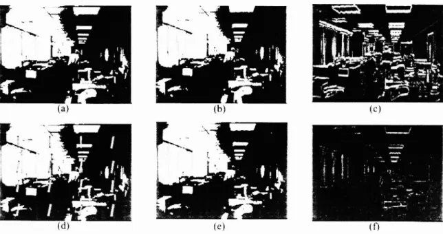
seems that Eq.(8) is a little complicated for a practical implementation. Nevertheless, note that all the elements in the matrices can be treated as the inner product of two vectors and some of these entries are duplicated. This implies that this computation can be efficiently implemented with a fast algorithm of vector inner product. Figure 9 shows the simulation of motion compensation after using the affme model. Figure 9(a), (b) illustrate two consecutive image frames with a rotation motion. Figure 9(d) shows the valid local motion vectors after motion estimation and motion compensation. Based on thesevalid motion vectors, we calculate the coefficients of affme transform and Figure 9(e) shows the stabilized image frame.
Figure 9(c) and 9(f)showsthe intensity difference before and after motion compensation.
6.CONCLUSION
In this paper, we design a fme division method for block matching over gray-coded bit-planes to acquire high performance of stabilization. We also design our new strategies to efficiently detect moving object and intentional panning by using the
test of random like motion and temporally correlated motion. The affme transform is used for motion compensation to
model camera motion with rotation. Based on this architecture, a "real-time" motion estimation hardware interconnecting with a microprocessor is designed too, and it has already been implemented on FPGA 10K 100.
Figure 9. The simulation results: (a) the reference frame (b) the compared frame (c) dif6rence hetv'een (a) and (b) (d)validlocal motion vectors (e)thealigned frame without interpolation (0 difference between (a) and (e).
REFERENCE
[lj Joon Ki Paik. Yong Chul Park. and Dong Wook Kim. "An Adaptive Motion Decision System for Digital Image Stabilizer Based on Edge Pattern Matching", IEEE Trans. on Consumer Eh'ctronics, Vol. 38, No.3. AUGUST 1992. [21 Kenya Uomon, Atsushi Morimura, Hirofumi lshii. Takashi Sakaguchi. and Yoshinori Kitamura. "Automatic Image
Stabilizing System by Full-digital Signal Processing", IEEE Trans. oiz Consumer Electronics.
Vol.36, No.3,
AUGUST 1990.
[31 Toshiro Kinugasa, Naoki Yamamoto, and lliroyuki Komatsu, "Electronic Image Stabilizer for Video Camera Use",
IEEE Trans. on Consumer Electronics, Vol. 36. No. 3, AUGUST 1990.
[4] Yo Egusa, Hiroshi Akahori, Atsushi Morimura, and Noboru Wakami. "An Application of Fuzzy Set Theory for an Electronic Video Camera Image Stabilizer", IEEE Trans. on PuzvSystems, Vol.3, No.3, AUGUST 1995.
[5] Yo Egusa. Hiroshi Akahori, Atsushi Morimura. and Noboru Wakanii, "An Electronic Video Camera Image Stabilizer Operated on Fuzzy Theory". IEEE 1992.
[6] Carlos Morimoto, and Rama Chellappa, "Evaluation oflmage Stabilization Algorithms", IEEE 1998.
[7] Masayoshi Sekine, Toshiaki Kondou, and Hisataka Hirose, "Motion Vector Detecting System for Video Images
Stabilizers", IEEE Trans. on Consumer Electronics, 1994.
[8] Sung-Hee Lee, Kyung-Hoon Lee, and Sung-Jea Ko, "Digital Image Stabilizing Algorithms Based on Bit-plane
Matching", IEEE 1998.
[911 Sung-Hee Lee, Seung-Won Jeon, Eui-Sung Kang and Sung-Jea Ko, "Fast Digital Stabilizer based on Gray Coded Bit-Plane Matching", IEEE Trans. on Consumer Electronics, Vol. 45, No.3, AUGUST 1999.
[10] Jung-Hyun Hwang, Hweihn Chung, Sung-Il Su, Yong-Chul Park, and Chul-Ho Lee, "High Resolution Digital Zoom Using Temporal hR Filter", IEEE Trans. on Consumer Electronics, Vol. 424, No.3, AUGUST 1996.
[11] Joon Ki Paik, Yong Chul Park, and Sung Wook Park, "An Edge Detection Approach to Digital Image Stabilization
Based on Tn-state Adaptive Linear Neurons", IEEE Trans. on Consumer Electronics, Vol. 37, No. 3, AUGUST 1991. [12] M. Hansen, P. Anandan, K. Dana, G. van der Wal, and P. Burt, "Real-time Scene Stabilization and Mosaic