450 IEEE COMMUNICATIONS LETTERS, VOL. 5, NO. 11, NOVEMBER 2001
A Multicast Mechanism for Mobile Networks
Yi-Bing Lin, Senior Member, IEEE
Abstract—This letter proposes a multicast table approach to
support GSM/UMTS multicast that minimizes the paging cost. The implementation and execution of the multicast tables are very ef-ficient. The costs for updating these tables can be ignored com-pared with the costs of standard location update procedures. Fur-thermore, our mechanism can be implemented within the mobility databases without modifying the standard location update mes-sages. We show that our mechanism always outperforms the ex-isting GSM/UMTS multicast mechanisms.
Index Terms—Mobile network, multicast, UMTS.
I. INTRODUCTION
E
XISTING 2G and 3G systems do not support efficient multicast mechanism. In [1], Universal Mobile Telecom-munication System (UMTS) provides voice group call service through a broadcast mechanism. Specifically, all service areas are paged when a voice call is delivered. That is, a service area is paged even if no multicast user is in that area. In iSMS [2], mul-ticast is achieved by sending every message to individual users in the multicast list. If users are in a service area, then the same message is sent times to this service area. The above two ap-proaches are clearly not effective. In this letter, we describe an efficient multicast mechanism for UMTS [3], which minimize the number of messages sent to the service areas. This multicast mechanism can be used to deliver short messages or multimedia messages. In UMTS, short messages are delivered through the control plane of the circuit switched (CS) domain. On the other hand, multimedia messages are delivered through the user plane of the packet switched (PS) domain. We will describe our multi-cast mechanism in the CS domain (which is basically the same as GSM). The mechanism for the PS domain is similar, and will not be elaborated.UMTS networks track the locations of mobile stations (MSs) so that incoming calls can be delivered to the subscribers. To exercise location tracking, a UMTS service area is partitioned into several location areas (LAs). Every LA consists of a group of base stations that communicate with the MSs over radio link. The major task of mobility management [4], [5] is to update the location of an MS when it moves from one LA to another. The location information is stored in the UMTS mobility databases such as the home location register (HLR) and the visitor location register (VLR). Every VLR maintains the information of a group of LAs. In the UMTS CS domain, our multicast
Manuscript received June 22, 2001. The associate editor coordinating the re-view of this letter and approving it for publication was Dr. C. Douligeris. This work was supported by MOE Program of Excellence Research under Contract 90-E-FA04-4.
The author is with the Department of Computer Science and Information En-gineering, National Chiao Tung University, Hsinchu, Taiwan, R.O.C. (e-mail: [email protected]).
Publisher Item Identifier S 1089-7798(01)10758-1.
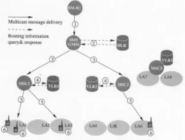
Fig. 1. The GSM/UMTS short message multicast architecture.
mechanism utilizes the existing UMTS/GSM short message architecture as shown in Fig. 1. In this architecture, there are three VLRs: VLR1, VLR2, and VLR3. VLR1 covers location areas LA1, LA2, and LA3. VLR2 covers location areas LA4, LA5, and LA6. VLR3 covers location areas LA7 and LA8. The multicast messages are issued by the short message service center (SM-SC). Following the standard UMTS/GSM proce-dures, every multicast group is associated with a short message service (SMS) gateway mobile switching center (GMSC), and the SM-SC always forward messages to the SMS GMSC of the multicast group. The SMS GMSC then forward the message to the MSCs where the multicast members reside. The SMS GMSC can be one of the terminating MSCs. The MSC’s then page the LA’s of the multicast members. In Fig. 1 the logical path for message multicast is (1) (3) (5) (6). Note that in this procedure, the HLR and the corresponding VLR’s are queried to identify the MS’s of the multicast members (see (2) and (4) in Fig. 1).
Two types of tables are utilized in the multicast mechanism. In the HLR, we implement a table that contains the ad-dresses of the VLR’s and the numbers of multicast members residing in the VLR’s. In every VLR, we implement a table that contains the identities of the LA’s and the number of the multicast members in these LA’s. Consider the example in Fig. 1. There are two MS’s in LA1, one MS in LA3, and one MS in LA6. Thus
(1)
LIN: A MULTICAST MECHANISM FOR MOBILE NETWORKS 451
In this letter, we describe the UMTS/GSM multicast mecha-nism based on the multicast tables. Section II shows how the multicast tables and are maintained through the standard GSM/UMTS location update procedures. Section III describes how messages are multicasted by using the multicast tables. Section IV investigates the performance of the multicast mechanism.
II. LOCATIONTRACKING OF THEMULTICASTMEMBERS
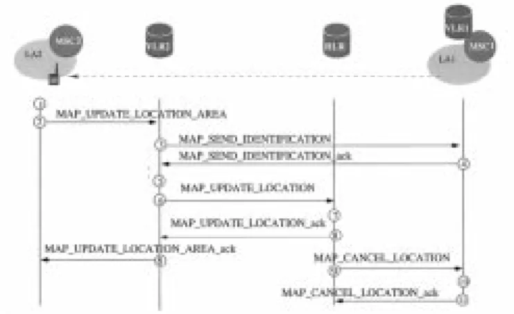
This section describes the GSM/UMTS location update pro-cedure, and shows how the multicast tables and are maintained through this procedure. We assume that exactly one MSC is connected to a VLR. This one-MSC-per-VLR configuration is typical implementation in the existing GSM/UMTS systems. Two types of movements are considered: inter-LA movement and inter-VLR movement. In inter-VLR movement, the old and new LA’s are connected to different MSC’s and thus different VLR’s. In Fig. 1 assume that the MS of LA3 moves into LA4. The location update message flow is given in Fig. 2. In this figure, the messages with prefixMAP
are defined in GSM/UMTS standards. The steps are described as follows.
Step 1) A location update request message is sent from the MS to MSC2. MSC2 sends the message
MAP UPDATE LOCATION AREAto VLR2. Step 2) Since the MS is a new visitor to VLR2, VLR2 does
not have a VLR record of the MS. According to the message received from MSC2 at Step 1, VLR2 identifies the address of the previous VLR. Step 3) VLR2 asks VLR1 to retrieve the International
Mo-bile Subscriber Identity (IMSI) of the MS in the database. IMSI is the unique subscriber identity which identifies the HLR of the MS.
Step 4) The IMSI is sent back from VLR1 to VLR2. VLR2 creates a VLR record for the MS, updates the LA Identity and the MSC fields of the VLR record, and derives the HLR address of the MS from the MS’s IMSI.
Step 5) (in VLR2) is incremented by 1. Step 6) The VLR2 sends theMAP UPDATE LOCATION
message to the HLR. By using the received IMSI, the HLR identifies the MS’s record. The MSC number and VLR address fields of the record are updated.
Step 7) is decremented by 1, and is incremented by 1.
Step 8) An acknowledgment is sent back to VLR2. Step 9) The HLR asks VLR1 to delete the obsolete record
of the MS.
Step 10) (in VLR1) is decremented by 1. Step 11) VLR1 acknowledges the location cancelation. In this procedure, Steps 1–4, 6, 8, 9, and 11 are defined in the standard UMTS/GSM specifications. Steps 5, 7, and 10 are executed if the MS is a multicast member. Be-fore the registration, the contents of the multicast tables are given in (1). After the registration, for VLR3 remains the same. becomes ,
Fig. 2. Registration for a multicast member (inter-VLR movement).
, and . for
VLR1 becomes , , and
. for VLR2 becomes ,
, and .
For inter-LA (intra-VLR) movement, only Steps 1, 2, 5, and 8 in Fig. 2 are executed. In Fig. 1, if an MS moves from LA1 to LA2, the inter-LA registration is performed. Before the registra-tion, the contents of the multicast tables are given in (1). After the registration, , for VLR2, and for VLR3 remain the same, and for VLR1 becomes
, , .
From the descriptions of the above procedure, it is apparent that the tables and s accurately record the multicast members distributed in the LA’s of an UMTS network.
III. MOBILEMULTICASTMESSAGEDELIVERY
This section describes how messages are multicasted by using the multicast tables. The procedure is described in the following steps (see Fig. 1).
Step 1: The SM-SC sends a multicast message to the SMS GMSC.
Step 2: The SMS GMSC requests the routing informa-tion from the HLR. The HLR searches the multicast table . If , then the mobile station roaming number (MSRN) for the is returned from the HLR to the SMS GMSC through
MAP SEND ROUTING INFO FOR SM ack. MSRN is used to identify the destination MSC of the message. Step 3: The SMS GMSC delivers the multicast message to the destination MSC’s (based on the MSRN’s received from the HLR). In Fig. 1, the multicast message is sent to MSC1 and MSC2.
Step 4: Every destination MSC queries its VLR to ob-tain the subscriber-related information. When the VLR receives this message, it searches the multicast table to identify the LA’s where the multicast members reside. These location areas satisfy the condition . In Fig. 1, the LA’s in VLR1 are LA1 and LA3. The LA in VLR2 is LA6. A micro procedure Check Indication in the VLR is invoked to verify the data value of the message. If the tests are passed, the VLR requests the MSC to page .
452 IEEE COMMUNICATIONS LETTERS, VOL. 5, NO. 11, NOVEMBER 2001
Step 5 and 6: The MSC broadcasts the message to the multicast members in the LA’s following the standard GSM/UMTS paging procedures. The multicast members listen and receive the message broadcasted in the LA’s. In the above message delivery procedure, only the LA’s with multicast members will be paged for multicast. The LA’s without multicast members will not be paged.
IV. PERFORMANCEEVALUATION ANDCONCLUSIONS
This section investigates the performance of the three multi-cast approaches:
Approach is used in UMTS voice group call service [1] (where the voice calls are replaced by short messages). In this approach all LA’s are paged when a multicast message arrives.
Approach is used in iSMS [2] where multicast is achieved by sending a message to every individual member in the multicast list.
Approach is our approach based on multicast tables. This approach pages the LA’s where the multicast mem-bers reside. The LA’s without multicast memmem-bers are not paged.
The multicast costs of above approaches are measured by the number of paging messages sent to the LA’s at multicast mes-sage delivery. For the particular multicast mesmes-sage delivery in Fig. 1, the multicast costs for , , and are 8, 4, and 3, respectively.
Assume that the LA’s are classified into categories. For , there are LA’s of class . Let be the number of LA’s in the UMTS system. Consider two random variables and . When a multicast message arrives, there are multicast members in the UMTS system, and these members are distributed among LA’s (where ). It is clear that the expected multicast costs for , and are , , and , respectively. Let and be the expected costs for
and normalized by the cost of . Then
and (2)
The normalized costs and were derived in [3], which can be expressed as
and
(3) where is the traffic intensity of class . Based on (3), we in-vestigate the performance of , , and . We consider two classes of LA’s. A class 1 LA has multicast user traffic
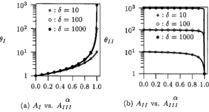
Fig. 3. Performance of the multicast mechanism.
, and a class 2 LA has the traffic . If , a class 1 LA has small multicast member population, and a class 2 LA has large multicast member population. Let be the por-tion of class 1 LA’s. That is, , and . Fig. 3 plots and against . From the previous discussion, it is likely that there is no multicast member in a class 1 LA, and there are many members in a class 2 LA’s. Thus as in-creases, increases [Fig. 3(a)], and decreases [Fig. 3(b)]. When , and have similar performance (i.e., ). When , and have similar perfor-mance. On the other hand, significantly outperforms when (that is, when more than 30% of the LA’s have few multicast members). Also, significantly outperforms when (that is, when less than 90% of the LA’s have many multicast members). To conclude, always out-performs and , and we quantitatively show the scenarios when significantly outperforms the previously proposed approaches.
As a final remark, the implementation and execution of the multicast tables are very efficient. The cost for updating these tables can be ignored compared with the standard location update steps (location update message sending and VLR/HLR record modifications). Furthermore, our mechanism can be implemented within the VLR’s and the HLR without modifying the standard location update messages.
REFERENCES
[1] “3rd Generation Partnership Project; Technical Specification Group Core Network; Voice Group Call Service (VGCS)—Stage 2 (Release 4),”, 3G TS 43.068 V4.2.1, 2000.
[2] C. H. Rao, D.-F. Chang, and Y.-B. Lin, “iSMS: An integration platform for short message service and IP networks,” IEEE Network, vol. 15, no. 2, pp. 48–55, 2001.
[3] Y.-B. Lin, “A multicast mechanism for mobile communications net-works,”, U. S. Patent pending, 2001.
[4] Y.-B. Lin and I. Chlamtac, Wireless and Mobile Network Architectures: John Wiley & Sons, 2001.
[5] I. F. Akyildiz, J. McNair, J. S. M. Ho, H. Uzunalioglu, and W. Wang, “Mobility management in next generation wireless systems,” Proc.