Optimal Frame Pattern
Design for a
TDMA
Mobile Communication System
Using a Simulated Annealing Algorithm
Chung-Ju Chang,
Member, IEEE,and Chen-Hsiang Wu
Abstmct- Different relative positions of voice and data slots within the frame of a TDMA mobile communication system may result in different system data throughput. The optimal relative position, namely the frame pattern which can achieve maximum data throughput, is designed in this paper. This design method can be formulated as solving a combinatorial optimiza- tion problem. Generally, the global optimal solution of such a problem is hard to find using conventional methods, which may be computationally intractable. A reliable and effective method called a simulated annealing algorithm is applied to obtaining the global optimum. Numerical results reveal that there exist various optimal frame patterns for different ranges of traffic load and the optimal frame pattern can achieve m a t throughput improvement over a random frame pattern.
I. INTRODUCI'ION
S is well known, cellular mobile communications render
A
convenient service and are widely used. The growing public acceptance has saturated capacity of the first generation system, which is based on analog voice transmission. In order to improve spectrum efficiency, second generation systems are being introduced with digital transmission technology. Various systems with different architectures, frequency divi- sion multiple access(FDMA),
time division multiple access(TPMA), and code division multiple access (CDMA), have been proposed for digital radio. Among these, the
TDMA
structure supports users flexibiZiQ of choosing their own de- sired rates of communications and proper level of coding according to the nature of the transmitted traffic. This inte- gration potential makes TDMA welcomed and widely adopted [7], [8]. Also, in addition to the traditional voice service, data service applications like sending maintenance instructions for repair personnel are becoming common. Therefore, the
TDMA
system will be expected to provide integrated voice and data services.
Many efforts in the literature have been devoted to finding an efficient multiplexing strategy for integrating voice and data. In traditional
FDMA
mobile systems, integration is provided by handling each type of communications separatelyManuscript received April 14, 1992; revised June 22, 1992 and October 20, 1992. This work was supported in part by the Telecommunication Laboratories, Ministry of Transportation and Communication under Contract TL-NSC-81-2102 and by the National Science Council, Taiwan, Republic of China under Contract NSC81-0404-E-009-002.
The authors are with the Department of Communication Engineering, National Chiao Tung University, Hsinchu, Taiwan 300, Republic of China.
IEEE Log Number 9207173.
and thus establishing two effectively independent subsystems within each vehicle [9]. Since such an architecture duplicates equipment, wastes channel space, and responds poorly to traffic change, an efficient approach is proposed by [lo], [ll], and [15] where the integration of voice and data is implemented by placing data into the silence gaps of voice. This policy can upgrade a conventional voice-only system to an integrated voice and data system without compromising voice performance.
There are also two multiplexing approaches for integrating voice and data in the TDMA mobile system. One is the fixed boundary multiplexing scheme that partitions a TDMA frame into two subframes, where the voice subframe and data subframe are dedicated to voice and data, respectively. This scheme faces the problem of an insensitive response to the traffic change of voice or data. The other scheme is the movable boundary multiplexing scheme that allows a data user to borrow idle slots within the voice subframe. It can
dynamically use free slots so as to improve utilization [2], [121, [ W , 1171.
Due to the difference of delay and quality requirements for voice and data traffic in the integrated services TDMA mobile communication system, different transmission modes for voice and data slots are used. A central assignment and synchronous transmission mode is usually provided for voice traffic, while a distributed assignment and contention transmission mode is adopted for data traffic. As such, the positions of available data slots within a frame (called the frame pattern in this paper) should affect the data performance of the system. Generally speaking, the system will gather more ready packets awaiting transmission for a frame pattern with longer intervals between two neighboring data slots, and this will result in higher probability of packet collision at heavy traffic load. Thus when heavy traffic occurs, the frame pattern with data slots merged together is expected to have better throughput than the other frame patterns, such as the one with data slots uniformly distributed over a frame. We shall explain the phenomenon more clearly in a later section. This paper provides an algorithm to determine the best data slot positions for a given data traffic load so that the performance criterion, system data throughput, is maximized.
In this paper, the optimal frame pattern for an integrated voice and data TDMA mobile communication system is de- signed. The design problem is formulated as a global optimiza- tion procedure in which the system data throughput as the cost 0018-9598/93$03.00 0 1993 IEEE
~
206
function will be optimized by properly adjusting the positions of available data slots via an algorithm called simulated annealing. This simulated annealing algorithm is a reliable and effective approach to solving this combinatorial optimization problem; it is often more efficient than an exhaustive search yet more robust than gradient descent. The details of this algorithm will be introduced later and numerical examples will show that there are various optimal frame patterns for different ranges of traffic load. Incidentally, if the optimal frame pattern alters as the offered data traffic load changes, the adjustment of data slot positions to the optimal one can be carried out by an automatic time-slot reassignment protocol. A similar protocol can be found in [l].
In Section I1 of this paper, formulation of the frame pattern and a model for an integrated voice and data TDMA mobile communication system are given, and system data throughput for a given frame pattern is obtained. Section 111 is devoted to finding the optimal frame pattern by the simulated anneal- ing algorithm. Some numerical illustrations are discussed in Section IV. The conclusion is presented in Section V.
IEEE TRANSACTIONS ON VEHICULAR TECHNOLQGY, VOL. 42, NO. 2, MAY 1993
11. FRAME PATIERN AND DATA THROUGHPUT
A. The Frame Pattern
In an integrated voice and data TDMA mobile communica- tion system, the entire frequency band is usually divided into a number of duplex channel pairs. One channel of each pair is for the down link and is configured in TDM mode, while the other channel is for the up link and is configured in TDMA mode [8]. The TDMA link is usually synchronized With the TDM link, but with a half-frame offset to preclude the need for the mobile to transmit and receive simultaneously [l].
Within the TDMA link, a synchronous transmission mode is provided for voice but a contention mode is provided for data. In this paper, we assume that a movable boundary multiplexing scheme is adopted in the uplink channel, where the data traffic can use both its own nominal data slots and the unassigned voice slots but it can not use the silence gaps of assigned voice slots; we also assume that there are N independent slots in a frame of the TDMA link, and Nt slots among the N slots are assigned for data service while the remaining (N- N t ) slots are assigned for voice traffic. Thus N t , the total number of slots available for data transmission at a given time, is the sum of nominal data slots and the unassigned voice slots.
As
shown in Fig. 1, let d; denote the slot number in a frame of the ith available data slot, where 15
i5
N t , 15
d;5
N , and dl<
dz<
<
dNt.
The notation d;+
l(d;-
1) refers to the slot immediately after (before) d;, which may be a voice or data slot. Also, let z; be the interdistance between two successive data slots d;+l and d;, where the notation d;+l refers to the first data slot following d i . Thus z; is given by(1) = di+l
-
di 7 i f i = 1 , 2 , . . - , N t - 1 .{
dl+
N-
dNt, if i = Nt.Note that 5 ; , 2 2 , . - . , 2 ~ ~
2
1. We call ( 2 1 , 2 2 , . . . , 2 ~ ~ ) the frame pattern of the integrated voice and data TDMA mobile communication system, where 05
Nt5
N. The frame pattern0.1
b
0.2 0.4 0.6 0.8 1.0 1.2 JTRAFFIC LOAD G Fig. 1.
extrac6 the feature of interdistance of two successive data slots in a frame. We denote a particular frame pattern by
X ( N t ) ,
and denote the set of all possible frame patterns by U ( X ( N t ) ) which is formulated asU ( X ( N t ) ) =
{ W K )
= (21,22,.'*,ZNt)lz ~ , z ~ , . . . , x N ~ 2 1 , a n d 2 1 + 2 2 + . . . + ~ ~ , = N } . (2) B. The Mean Data Throughput
assume the following.
Before obtaining the mean data throughput per slot, we 1. The holding time of the voice call is much longer than the frame time so that the queueing behavior of data for a given Nt frame pattern can reach steady state. 2. The total data traffic, new and retransmitted, constitutes
a Poisson process with mean arrival rate G packets/slot. 3. The slotted ALOHA random access protocol is assumed
for data transmission.
Based on the above assumptions, the mean data throughput given a specific frame pattern X ( N t ) in U ( X ( N t ) ) , denoted by
SxcNt,,
can be given by(3) G N t
=
-
.
xi.
e - - .sx(Nt)
Nt i=lFrom (3), we can see that various frame patterns may result in different mean data throughput. Of all these patterns in U ( X ( N t ) ) , there must exist an optimal frame pattern which achieves the largest mean data throughput. However, there are many frame patterns for a given Nt slots in N , say 7.5394 x lo1' for N = 60, Nt = 10. A brute-force search for an optimal frame pattern is too difficult-possibly even impossible. The next section of this paper will be devoted to finding the optimal solution via an efficient and robust optimization algorithm-simulated annealing.
111.
THE
OF'TIMAL W EPATERN DESIGN BY SIMULATED ANNEALINGA. The Simulated Annealing Algorithm
For a given combinatorial optimization problem, there are many feasible solution states
X
which collect to form a solution state spaceU ,
and there is a cost functionC
which assigns eachX
inU
a cost C ( X ) . The(U,
C(U))
can beimagined as a land which consists of mountains and valleys whose height represents the corresponding cost. The goal of
= random number in (0, 1)
IF ( T <Accept(Ac,T)) THEN
the optimization is to find the deepest valley, meaning the minimum cost. Traditional iterative improvement heuristics generate a random walk in the land and a move is adopted if the move maximally reduces the cost. This “greedy strategy” can easily trap the final solution into a local minimum. The deepest valley might be located far from the local minimum and can be reached only after hill climbing.
The simulated annealing, however, allows a move to climb hills, in addition to the welcomed move to lower cost. It controls the ability of this climbing in a manner analogous to physical solid annealing: raising the temperature so that the particles of solid are equipped with high energy to fully randomly arrange in the liquid phase, followed by a cooling process to decrease temperature so as to force the uniform particles into a regular lattice [4]. This simulated annealing algorithm is essentially a robust probabilistic algorithm to solve complex combinatorial optimization problems with good quality. Its robustness results from its guaranteed convergence to global optimum and its independence of the final solution on the initial point [3]. It is more efficient than an exhaustive search and more robust than gradient descent.
In this algorithm, an externally specified parameter T , analogous to the temperature in physical annealing, is used to indicate the ability to climb hills. The move to a higher cost point is sometimes permitted with probability positively proportional to T. As in physical annealing, T is initialized to a high value so that the simulated annealing can hardly distinguish valleys or mountains, rendering the initial point a practically complete freedom to visit everywhere in the land. After a number of walks, it is expected that a roughly lower region has been found and the freedom to wander should be restricted. As the algorithm progresses, T is gradually decreased and the search is systematically concentrated into regions likely to contain a global optimum, but still random enough to escape most local optimums. After T has decreased so small that the probability of escaping from the present valley is negligible, T is set to zero and the greedy strategy, in which no more hill climbing moves are allowed, starts to find the optimal solution in the final concentrated valley. The convergence to the global optimum is shown to be provable with probability one sense [13].
Based on the above concept and the references [3], [4], the general structure of the simulated annealing algorithm is stated as follows.
Simulated Annealing Algorithm Step 0: [Initialize]
Initialize the effective temperature To and ran- domly choose an initial state
X,
fromU.
Step 1: [Generate a new solution state ]A new solution state
X,
is generated byX,
=Generute(X;). Step 2: [State Transition]
A C = C ( X , ) - C ( X , )
The new solution state
Xj
is accepted byxi
exj.
ELSE
The new solution state
Xj
is rejected. Step 3: [Inner Loop Criterion Checking]IF (inner loop criterion is satisfied) Executive Step 4 to decrease T . ELSE
Repeat Steps 1-3. Step 4: [Temperature Cooling]
A new lower T is updated by T = Update(T). Step 5: [Outer Loop Criterion Checking]
IF (outer loop criterion is satisfied) THEN Execute Step 6.
ELSE
Repeat Steps 1-5. Step 6: [Greedy Strategy]
T = O
A greedy strategy starts to find the local optimum. END
There are six parameters involved above, which perform within the algorithm in the following manner: (i) Initial effective temperature TO is chosen so that the initial acceptance probability of a move to a high-cost solution state is large, (ii) Function Generute(Xi) is to perturb a new solution state
Xj
from the present state X i , (iii) Function Accept(Ac, T)is to determine the permission of the move from
Xi
to X j , (iv) Inner Loop Criterion is to check whether an equilibrium condition of the move at the temperature T has been reached, or whether a sufficient number of moves has been tried to reach an equilibrium condition at this temperature T, (v) Function Update(T) is to decrease the present T to a new lower value, and (vi) Outer Loop Criterion is used to decide whether the T is low enough to stop the cooling process of the simulated annealing algorithm. These parameters characterize and qualify the simulated annealing algorithm and have to be decided before the simulated annealing is applied to a particular problem. We shall describe them more clearly in the next subsection. The four parameters in (i), (iv), (v), and (vi) are, additionally, called the annealing schedule for their influence on the annealing of T. Many efforts have been devoted to finding a generally good choice of these parameters to make the simulated annealing efficient and accurate [3], [5]. There is an adaptive annealing schedule developed in [ 31 which shows significant improvement in efficiency over a simplified schedule and a geometric schedule. The reader can refer to it for more details.~
208 IEEE TRANSACTIONS ON VEHICULAR TECHNOLOGY, VOL. 42, NO. 2, MAY 1993
B. The Optimal Frame Pattern Design
In this subsection, we will determine the optimal frame pattern for the
TDMA
mobile communication system via the simulated annealing algorithm with the adaptive annealing schedule proposed in [3]. We define the solution state space to be the U ( X ( N t ) ) given in (2) and the corresponding cost function C ( X ) to be the negative of the mean data throughput ’ X ( N , ) given by(4) The six parameters of simulated annealing are chosen as follows.
(i) Initial TO
Usually, the initial temperature To is chosen high enough to
approach infinity so that any kind of move is always permitted and the solution state space can be explored completely. However, a higher TO results in a longer sequence of T
and hence slow convergence speed. Hence TO = 10a,(C) is chosen here, where a,(C) is the standard deviation of the cost of explored states at T = 00. Notice that a,(C)
and the corresponding expectation E,(C) can be estimated
from a number of randomly generated solution states since there is no preference among solution states at T = 00. The
procedure to determine the number of randomly generated solution states is to select a small positive integer number at first, randomly generate several sets of solution states according to the number, and then check whether all the above generated sets produce nearly the same estimate of the expected value and standard deviation. If all the sets produce the same estimate of the expected value and standard deviation, the number is decided; otherwise, the number of sets is increased and the above procedure is repeated. In our problem, TO = 10a,(C) is large enough to maintain quite high acceptance probability.
(ii) NGenerate(Xi)
A new solution state X j is generated from X i by choosing a move from a move set
M
which contains all feasible moves. For a given applied problem, the feasible moves inM
depend on the corresponding solution space and are required to be defined. Moreover, theM
should be complete so that there exists a finite number of moves to connect any two arbitrary solution states. In our problem, we define move ( i , j ) inM
to be the move which moves the present solution state X i = ( x ~ , x ~ , . . . , x N , ) to a new solution state X . - ( - z1,x2,..
,z;+
1 , ..
,
xj - 1 , .. .
,
X N i ) , where i#
j ,and 1
5
i, j5
Nt.
These Nt ( Nt - 1) moves inM
guarantee the completeness. The above move is called a basic move. In addition to this, we also define a complex move which consists of a batch of basic moves. The complex move is equivalent to a batch of basic moves carried out in sequence at once, and its cost is evaluated only after the last move of the sequence has been completed. This move can “tunnel” through hills and thus speed up the convergence [3, pp. 991.The adaptive generate function in [3] is adopted here. This method determines the selection probabilities of the moves from the data collected during the execution of the algorithm, and a new move is selected among all feasible types of moves according to the selection probability which is proportional to its quality factor. For the sake of fast convergence, a welcomed type of move is one which results in sizable perturbation of the cost while maintaining a reasonable chance of being selected [3, pp. 981. To rank the desirability of a move m, its quality factor Qm and selection probability Pm are therefore defined by a= (m) S k ( m ) Qm = and Qm Pm =
-
CQ-
(5) Mwhere the u,(m) and the ut(m) are the numbers of ac- cepted and attempted moves of type m , respectively, and the
S k ( m ) = I C ( X j ) - C ( X i ) l is the absolute value of the change of cost produced by the kth accepted type-m move. (ii) Accept( A c , T )
The acceptance probability should increase with the increase in T but decrease with the increase in cost change A c after a move. Thus Accept(Ac, T) should be monotonically increasing with T but monotonically decreasing with A c . Here, we adopt the welcomed Metropolis rule in [3], [4] as the Accept(Ac, T) in our problem. It is given by
Accept(Ac, T ) = min
[
1 9 exp(
--$)I.
(7)(iv) Inner Loop Criterion
From the theoretical simulated annealing analysis in [3, pp. 1231, the distance from collected data of cost C ( X ) to global minimum cost C*, ( C ( X ) -
C*),
is distributed in gamma density. Therefore, the inner loop criterion is to test whether a sufficient number of moves has been tried so that the distance is distributed with the gamma function. This task is carried out in three steps, as described below.1. The shape parameter a and the scale parameter X of the predicted gamma distribution
r ( a ,
A) [14] at temperatureT in terms of E, [C] and am (C) are determined. They are given in [3] and are rewritten as
and
where ET[C] and C T ( C ) are obtained by (vi) Outer Loop Criterion
and
and "a" is given by
2. After the values of (Y and A are obtained, the predicted gamma distribution is available. We then test the average cost of the collected solution states by
The q is a parameter left for specification.
3. If the average test is passed, the Kolmogorov-Smirnov test is used to check the closeness to the predicted gamma distribution [6]. The distances from the n col- lected data of cost to the minimum cost are calculated and arranged in order of increasing magnitude. Let
{ yi 11
5
i5
n} denote the sequence of ordered distance, and a cumulative distribution function (CDF) for the yi's, denoted by A,( y), is defined byIt is reasonable to stop the cooling process of the simulated annealing when the algorithm has reached a local minimum and T is so small that the probability to escape from the local minimum is negligible. The occurrence of this situation is signaled when we apparently find that all the accessed states are of comparable costs in the present temperature. We therefore define the following outer loop criterion: The difference between the maximum and the minimum costs among accepted states at the present temperature T equals the maximum change in an accepted move at the same value of T.
The simulated annealing algorithm works in our application with acceptable computation time. A practical example is presented in the next section.
IV. NUMERICAL EXAMPLES AND DISCUSSIONS In this section, numerical examples are provided to show some interesting phenomena of optimal frame patterns. The optimal frame pattern is obtained by implementing a simulated annealing algorithm on a
VAX
8800 super minicomputer with the following simulated annealing parameters: q = 0.75, confidence coefficient of the Kolmogorov-Smirnov test equals 0.95 (and henceC
= 1 . 3 6 / f i with n collected data of costs). The phenomena of optimal frame patterns are investigated while varying G and N t .S
= 0.7, N,, = 200, "in = 10, rmin = 0.90, and theA . Optimal Frame Pattern Phenomena
traffic load G and their mean data throughputs versus G in the range of [O.O, 1.21 if N = 40 and Nt = 10. The FP* is
0, if Y
<
Y 1k / n , if Yk
5 5
yk+l, for 15
k
5
1, if Y2
- 1 (14)
Fig. 2 shows the optimal frame pattern (FP*) for various
Let F ( y ) denote the CDF of the predicted gamma distribution r(a,A), and define D,
-
m a y IF(y)-
A,(y)l. If D ,
< C,
these two distributions are said to be close enough. TheC
depends on the specified confidence coefficient and the number of collected data n. It can be obtained by looking up the table in [6]. The homogeneous theory developed in [3] proves that the convergence to global optimum is independent of the annealing schedule if an infinite number of iterations is executed to achieve equilibrium. However, for the sake of limited computation resources and for accuracy, an upper bound N,, and a lower bound "in of iterations in the inner loop are additionally set. If the upper bound N,, of interactions are taken and yet the data points are not sufficiently close to the predicted gamma distribution, T is decremented anyway.searched every 0.00125 in the range of G = [0.0,1.2]. We can see from the figure that the FP* = frame pattern (4, 4, 4, 4, 4, 4, 4, 4, 4, 4) when G is in the range of (0.0, 0.38251, FP* = (3, 3, 3, 3, 3, 3, 3, 3, 3, 13) when G is in [0.3838, 0.41251, FP* = (2, 2, 2, 2, 2, 2, 2, 2, 2, 22) when G is in [0.4138, 0.69251, and FP* = (1, 1, 1, 1, 1, 1, 1, 1, 1, 31) when G is in [0.6938, 1.201. There indeed exists an optimal frame pattern for a given G and N t , but none is always optimal for all G. Instead, there are various optimal frame patterns corresponding to different ranges of G. The phenomenon can be explained as follows. We know that the standard slotted ALOHA system has a maximum throughput 0.368 at traffic load G = 1 and, the heavier or the lighter the traffic load than G = 1, the smaller the throughput. In our system, as heavy traffic exists (e.g., G
2
l), a data slot having larger interdistance with its last neighboring data slot will gather more ready packets, resulting in a smaller throughput. Thus(v) Update(T) the extremely nonuniform frame pattern (1, 1, 1, 1, 1, 1, 1, 1,
1, 31) where most data slots are close neighbors will perform the best.
As
the traffic gets lighter (e.g., G<
0.6), a data slot This function is recommended by [31 and is given bywhich has a suitable interdistance with its last neighboring data slot so as to operate at an accumulated traffic load near 1 will produce a maximum throughput. Thus the optimal frame pattern is the pattern which produces the most such slots. This justifies that Fig. 2 has an optimal frame pattern ( 2 , 2 , 2 , 2 , 2 , 2 , 2 , 2 , 2 , 2 2 ) as G is around 0.5, and ( 4 , 4 , 4 , 4 , 4 , 4 , 4 , 4 , 4 , 4 ) as Update(T) = T max
[
exp(
--
g:i&)
7 .-in] (15)where
S
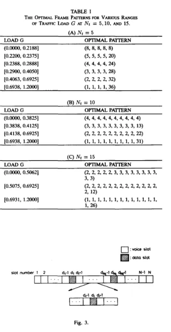
specifies the decrement rate of T and r,in is used to make sure that too fast annealing is avoided. Both r,in and210 IEEE TRANSACTIONS ON VEHICULAR TECHNOLOGY, VOL. 42, NO. 2, MAY 1993 . . . O b 0:2 014 016 0:s 1:O 1 . i TRAFFIC LOAD G . . . Fig. 2. TABLE I
THE OFTIMAL FRAME P ~ R N S FOR VARIOUS RANGES
OF TRAFFIC LOAD G AT Nt = 5,10, AND 15. (A) Nt = 5
LOAD G OPTIMAL PA’TTERN
(O.oo00, 0.21881 [0.2200, 0.23751 [0.2900, 0.40501 [0.6938, 1.20001 (8, 8, 8, 8, 8 ) (5, 5, 5,5, 20) (3, 3, 3, 3, 28) (1, 1, 1, 1, 36) r0.2388, 0.28881 (4,4,4,4,24) [0.4063, 0.69251 ~ 22,2,32) , (B) Nt = 10
LDAD G OPTIMAL PATIERN
(O.oo00, 0.38251 (4, 4, 4, 4, 4, 4, 4, 4, 4, 4) [0.3838, 0.41251 [0.4138, 0.69251 [0.6938, 1.20001 (3, 3, 3, 3, 3, 3, 3, 3, 3, 13) (2, 2, 2, 2, 2, 2, 2, 2, 2, 22) (1, 1, 1, 1, 1, 1, 1, 1, 1, 31)
G is around 0.25. Also, we can see in our example that as the traffic load is getting lighter, most slots in the optimal frame pattern enlarge their interdistance with their last neighboring data slot, and finally, for small G, the optimal frame pattern is the pattern with data slots distributed over the whole frame as uniformly as possible.
A further investigation of Fig. 2 finds that the optimal
frame pattern performs well in a preferred range and is not sensitive to a small change in G. In other words, the optimal frame pattern switches to the other one only at some discrete threshold of G and hence the total number of optimal frame patterns is finite. This fact is attributed to the reasons we used to explain the existence of an optimal frame pattern in some specific range of G in Fig. 2 and the restriction of integer solution for optimal frame pattern. Table I shows the optimal frame patterns for various Nt and G. Note that the total number of optimal frame patterns is 6, 4, 3 if Nt equals 5, 10, 15, respectively. Also notice that the finding of the optimal frame pattern (3, 3, 3, 3, 3, 3, 3, 3, 3, 13) in a small range of G at Nt = 10 identifies the value of careful search in simulated annealing. Furthermore, note that a maximum throughput 0.368 of a standard slotted ALOHA system occurs in the uniform optimal frame pattern (4, 4, 4, 4, 4, 4, 4, 4, 4, 4) at G = N t / N = 0.25. This situation is as expected, since all the slots of the uniform frame pattern operate at an accumulated traffic load of 1 packet and thus the system still has a maximum throughput 0.368.
B.
Throughput ImprovementFig. 3 shows a throughput comparison between a system with optimal frame pattern assignment and a system with random frame pattern assignment if N = 40 and Nt = 10. (Note that a random frame pattern assignment is typical of a system which does not implement a time-slot reassignment protocol and which has no dedicated data slots.) Here, the mean throughput of the system with random frame pattern assignment is obtained by averaging the throughputs of frame patterns randomly selected from U ( X ( N t ) ) over a quite large number. A great amount of throughput improvement is found, and the gain becomes larger with larger values of G. The gain ranges from 10%
-
120% and has nearly 25% improvementin moderate traffic at G = (0.2,O.S). The result is attractive
IC\ N+ = 15 \ - , ~ ” ~- MAD G OPTIMALPATIERN (O.oo00, 0.50621 (2, 2, 2, 2, 2, 3, 3, 3, 3, 3, 3, 3, 3, 3,3) [0.6931, 1.20001
0
: voice slot : data slot Fig. 3.and justifies the design of optimal frame pattern with time-slot reassignment protocol for our system.
V.
CONCLUSIONSThis paper develops a method for optimal frame pattern design in an integrated voice and data
TDMA
mobile commu- nication system. The method is formulated as a combinatorial optimization problem, and a simulated annealing algorithm is applied to finding the global optimal frame pattern so that the system data throughput is maximum. The simulated annealing algorithm is reliable and effective. The numerical results show that there are various optimal frame patterns in different ranges of traffic load G and finite optimal frame patterns exist in global G range. The numerical results alsoshow that the system can gain great throughput improvement by using optimal frame patterns.
[14] P. G. Hoel, S. C. Port, and C. J. Stone, Introduction to Probabilify
Theory. Boston, MA: Houghton M a i n , 1971, p, 129.
[15] D. J. Goodman, R. A. Valenzuela, K. T. Laird, and B. Ramamuirthi, “Packet reservation multiple access for local wireless communications,” in Proc. 38th IEEE Vek TechnoL Soc. Conf, May 1988, pp. 701-706.
1161 G. J. Coviello and P. A. Vena. “Inteeration of circuithacket switching
VI. ACKNOWLEDGEMENT
- -
The authors wish to thank the anonymous reviewers for their valuable suggestions to improve the presentation of this paper, and to Prof. Po-Rong Chang for his valuable discussion about
by a SENET (Slotted Envelope Network) concept,” in’conf Rec. 1975
[171
FJ.TpzyE
ekhF;i,
1 ~ ~ ~ P ~ . 4 ~ ~ ~ ~ n ~ ‘ ~ - ~ ~ h i t ~ r efor a flexible integrated voiceldata switch,” in Conf Rec. 1980 Int. Conj
the simulated annealing algorithm. Commun., May 1980, pp. 21.6-1 through 21.6-5.
REFERENCES
[ 11 Generic Framework Criteria for Universal Digital Portable Communi- cation Systems, FA-TSY-001013, Bellcore, Mar. 1990.
[2] D. P. Gaver and J. P. Lehoaky, “Channels that cooperatively service a data stream and voice message,” IEEE Trans. Commun, vol. COM-30, pp. 1151-1162, May 1982.
[3] F. I. Romeo, Simulated Annealing: Theory and Application to Layout Problems, Electronics Research Laboratory, University of California,
Berkeley, 1989.
[4] E. H. L. Aarts and P. J. M. Van Laarhoven, “Statistical cooling: A general approach to combinatorial optimization problems,” Philips J.
Res., vol. 40, no. 4, pp. 193-226, 1985.
[5] F. Catthoor and H. De Man, “Samirai: A general and efficient simulated- annealing schedule with fully adaptive annealing parameters,” Integra-
tion, The X S I Journal, pp. 147-178, 1988.
[6] P. G. Hoel, Introduction to Mothemtical Statistics. New York Wiley, [7] A. A. M. Saleh and L. J. Cimini, Jr., “Indoor radio communication using Time-Division Multiple Access with cyclical slow frequency hopping and coding,” IEEE J. Select. Areas Commun., vol. 7, pp. 59-70, Jan. 1989.
[8] J. D. Parsons and J. G. Gardiner, Mobile Communication Systems. New
York Wiley, 1989.
[9] H. P. Stern, “Design issues relevent to developing an integrated voice/data mobile radio system,” IEEE Veh. Technol. Conf, pp. 57-64, 1962, pp. 345-349.
June 1988.
-, “Design and performance analysis of an integrated voice/data mobile radio system,” IEEE Veh. Technol. Conf., pp. 300-305, May
1989.
J. S . Dasilva, “Performance analysis of land mobile packet systems,” Ph.D. dissertation, Dept. Syst. Comput. Eng., Carleton Univ., Ottawa, Ont., Canada, July 1980.
M. J. Fischer and T. C. Hams, “A model for the performance of integrated circuit-and packet-switched multiplexing structure,” IEEE
Trans. Commun., vol. COM-24, pp. 195-202, Feb. 1976.
E. Arts and J. Korst, Simulated annealing andBol&man machines:A Sto- chastic Approach to Combinaforial Optimization and Neural Computing.
New York Wiley, 1989.
Chung-Ju Chang (S%S-M’85) received the B.E.
and M.E. degrees in electronics engineering from National Chiao Tung University, Hsinchu, Taiwan, in 1972 and 1976, respectively, and the Ph.D. degree
in electrical engineering from National Taiwan University in 1985.
From 1976 to 1988 he was with the Telecom- munication Laboratories, Directorate General of Telecommunications, Ministry of co”unicatons, Republic of China, as a Design Engineer, Supervi- sor, Project Manager, and then Division Director. There, he was involved in designing digital switching system, ISDN user-
network interface, and ISDN service and technology trials. In the meantime, he also acted as a Science and Technical Advisor for Ministry of Communications from 1987 to 1989. In August 1988, he joined the faculty of the Department of Communication Engineering and Center for Telecommunications Research, National Chiao Tung University, where he is currently Associate Professor. His research interests include performance analysis, broadband networks, and mobile radio networks.
Dr. Chang is a member of the Chinese Institute of Engineers (CE).
include mobile cnmmuni’
Chen-Shiaq Wu was born in Taiwan on November 3, 1967. He received the B.S. degree in electron- ics engineering from Catholic Fu Jen University, and the M.S. degree in “munication engineering, from National chiao Tung University in 1990 and 1992, respectively.
He is now with the Telecommunication Labora- tories, Directorate General of Telecommunications, Ministry of Communications, Republic of China, as a design engineer. There, he is involved in digital subscriber loop technologies. His research interests cation and integrated services digital network.