Novel H ologra.phic Color Filters with Double Transmission H olograms \Veichung Chao and Sien Clii
Inst/lute (?fEiecIro—OpIicaI Engineering NaIioiicii (:'/'7ia() Tiing Utin'ersity,[Is/ilCliii, Taiiia,i PG Box 9-16/, (7hniung, Hsi,iChu S/i/en, Taiwan 310
Fax. 886-3-591 7479 eiiiaii: ii'ek'hung(äoes. i/ri. hi'
ABSTRA CT
A novel transmission structure of holographic color filters is introduced. The device is based on the natural characteristics of angular color dispersion in transmission holograms, and the optical reciprocity interacting with two same transmission structure. The type of holographic color filters, differed from before, is composed of two same structure of transmission holograms which are laminated on the both side of transparent substrate. The first transmission hologram diffract normally incident white light, generally emitted from metal halide lamp, into transparent substrate with angular color separation. The diffiacted beams transmitted through substrate and are separated for different R, G, B wavelengths. At last, the different R, G. B beams normally couple out with the second hologram as same structure as first one due to optical reciprocity. A light beam matrix mask (LBM) is presented to produce R. G, B pixeL and provided an approach in LCD application.
Key Words:Holographic Optical Elements, Diffiaction Optics, Color Filters Holographic Technology.
1.INTRODUCTION
Holographic optical elements based on phase volume holograms present a new optical function and a fantastic application in LCD projectors. Arrays ofcolored filters for LCD are made by reflection holography in dichrornated geltin'. The micro lens array (MLA), focuses the incident light into color cell aperture with a applied three hologram layers2. A diffiactive transmission grating is used for a compact spatio-chrornatic single-LCD projection architechture3. Holographic microlens matrices for selective focusing of a primary color is applied in single- and 3-LCD system4.
The advantage of volume holographic elements is the 100% theoretical diffraction efficiency in one diffraction order they can reach. Compared to method of multilayer thin film technique, the manufacturing process of phase volume hologram is simple by the beam interference exposure geometry. The mass production of phase volume hologram can also lead to low cost by using the optical duplication process from a holographic master. Multiple and complex optical frmnction can be completed by a specific superposition in same thickness scale of the thin film
A novel transmission structure for holographic color filters is introduced for LCD
application. This structure is based on the natural characteristics of angular color dispersion intransmission holograms and the optical reciprocity interacting with two same transmission
structures. The holographic color filters is composed of two same structure of transmission holograms which are laminated on the both side of transparent substrate. The first transmission hologram diffracts normally incident white light, generally emitted from metal halide lamp, into transparent substrate with angular color separation. The diffracted beam transmitted through substrate and are seperated for different R, G, B wavelengths. At last, the different R, G, B beamsnormally couple out with the second hologram as same structure as first one due to optical
reciprocity.2. BACKGROUND 2.1 Basic idea
Diffraction characteristics of phase volume transmision holograni is analyzed and based on the Kogelniks coupled wave theory. For the transmission holograms, the two beams construction is generally shown as in Fig. 1. The reference beam and object beam are formed a interference on
the same side of holographic recording material. The fringe period of volume transmission
hologram is illustrated as following form,A=
(I)
sin9 + sin&
where e1. and e are the incident angle of reference and object beam to surface normal respectively,
?
isthe wavelength of construction, and A is the fringe period of hologram.When reconstruction, the diffiaction property of transmission holograms can be also
maintained as the constructive format with a different reconstructed angle e1, a different
diffraction angle e2, and a reconstructed wavelength 7.A=.
. (2)sine1 + sine2
If the beam of construction and reconstruction are normal incidence to surface plane, i.e. e1' and er are equal to zero. Then, Eq.(2) can be simplified as following expression, Eq.(3). That mean, different reconstructed wavelength will have a different diffraction angle due to the natural characteristics of angular selection.
sin9
sin81(i)
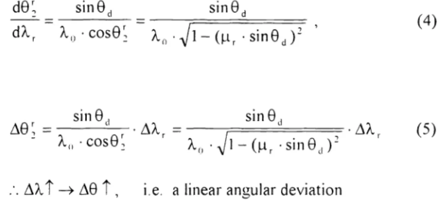
Slfled — Slfled dXr
X cose
-x
—(t,
•Slfled)-sine =______
-— z\ê '1', i.e. a linear angular deviation
where z\X isthe wavelength deviation from the reconstruction and tr=X
/
X0, it would cause a different color seperation in diffraction. If the white light is incident, the three primary colors areseperated to R, G, B.
(
Fig. I Construction geometry of phase volume transmission hologram. 2.2 Op*ical Reciprocity
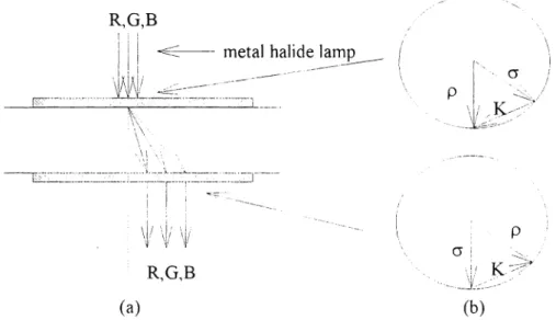
The holographic color filters, differed from before, is composed of two same structure of transmission holograms which are laminated on the both side of transparent substrate, as shown in Fig. 2. The first transmission hologram diffiact normally incident white light, generally emitted from metal halide or other light source, into transparent substrate with angular color separation. The diffracted beams transmitted through sLibstrate and are separated for different R, G, B Take a differentiation with respect to wavelength Xr. Eq.(3) can be rewritten by the following expression, Then, (4)
r
(5) sin eL,X, •l—( •sine(,)2
wavelengths. At last, the different R, G, B beams normally couple out with the second hologram as same structure as first one, i.e. calledoptical reciprocity as clearly seen the k-vector diagram in Fig. 2b. R,G,B /
L <i:
metaihalidelamp (.
_
AJ -
-I
pRGB
K4
(a) (b)Fig. 2 (a). Geometry of double transmission hologram, (b). K-vector diagram of optical reciprocity.
2.3 Characteristics of phase transmission hologram
The following equations are applied to calculate the spectral profile of theoretical diffraction efficency, as shown in Fig. 3. The spectral distribution of phase transmission hologram is wider due to the surface rainbow effect.
7
siir(jv +)
11= 7(1+ /r)
v=
/X•(CR •C)"2
dKcos(—e)—KXJ(4itn)
6C
()
whereCR =cose,and Cs = cose -2
cos(-e0) cos .
Theparameters C1, C is a measure of thewavelength at Bragg condition e0 S the incident angle at Bragg condition, and d is the grating thickness. The performance of transmission holograms, as exhibited by their diffraction efficiency and bandwidth, depends on their index modulation recorded in the film. However, the high index modulation ofholograrn will achieve a better performance ofvolurne hologram.
3. EFFICIENCY AND CHROMATICITY ANALYSIS 3.1 Diffraction efficiency
The theoretical diffraction efficiency spectral profile can be modelled by Eq. (6). The optical efficiency in each color distribution is shown as Fig. 3. The thickness of Fig. 3a is 40 urn, and Fig.3b is 50urn.In general, the optimum index modulation ofvolume transmission photopolymer can obtain a higher value up to 0.060, that mean, a high transmission efficiency.
1
ç
/\\
1p I
T, 1 1J,/
\ :
Ilix 0.5 —(
\ll
0.5
—, I / \/ —
ii \\I
I 0 \..Jjk./
o1
.;
400 500600 700
400 500 600 700 ?. (nni) x (nm)(a)
(b)Fig. 3 Thetheoretical DE in each color distribution with different thickness.
3.2 Chromaticity
The chrornaticity diagram is following CIE 1 93 1
standard with a comparision of
conventional color filter, as shown in Fig. 4. The theoretical analysis of chromaticity is larger than conventional color dyed filters.
4. PROCESS
To investigate the color seperation of phase transmission holograms, the constructed angle of transmission hologram were 0 degree and 20 degree, according to basic theory of transmission holograms. The transmission holographic recording films can be uitilized DCG or photopolymer for this experimental. The Du Pont holographic photopolymer materials is best way for our strucutre, such as HRF I 50, 600-001 or 609. HRF 1 50 has a film thickness of 38urn. HIR.F 600 have a optimal thickness 20 urn with higer index modulation up to 0.061. HRF 609 has a wider
spectra! characteristics. This photopo!yrner hologram is constructed by the dry processing which is fol!owed the steps of exposure, UV curing and baking. To record hologram, a 532nm Nd:YAG
!aser or 514 Argon laser is used for exposure, which the laser intensity was 2 rnW/cni2. The
optimal film speed ofDuPont HFR 600-001 is from 80 to 120 mi/cm2. The process ofUV curing was IOOmJ/cm2. Finally, the film was heated in an air-flowed oven at I 2OtT to 1 50°C for two hours for increasing the index modulation and efficency. The photopolyrner ofHRF 600-001 with a thickness of 20 urn is utilized for this structure. The R, G, and B color can easily be sperated in this double transmission holograms. But the FWHM bandwidth of real specrtral profile is 25 urn due to the thickness of T{RF 600. The multilayered phtopolymer structure may solve this problem.
To understande the color properties of phase volume holograms, we used the behavior of diffraction efficiency measurement to analyze the color seperation of photopolymer hologram. The measurement of diffraction property is realized by the setup of PDA optical spectrograph card. The type of the light source is metal halide lamp with a UV filter, and extend of illuminating light angle 5°. 1.00 — -i c)) S7)) 5111) 59(1 0.40 ——i .. 611) .4)) 1iwJ 47 .. . . o 1))) --.—-— A___ — — —— — 0.20 0 40 (1)6).)
Conventional CF
•
HCF(4Oum) A HCF(5Ouni) Fig. 4 The color chromaticity of theoretical approach in Fig.3.5. APPLICATION
Holographic color filters applied in LCD displays provide an important approach by
producing this filters with a holographic process. Especially, they are different from the
conventional type of colored dyes which are impregnated into a polymer matrix and thin film interference layers evaporated in a vacuum chamber. The advantage of holographic color filters is easier to produce than dyed filters and also have the properties of sharp edges with respect to thin film filters. Many technologies for manufacturing holographic filter is well known now, such as holographic mirror, holographic notch filter, holographic sun-protective glasses etc..The novel transmission structure is based on the natural characteristics of wider angular color dispersion in transmission holograms and the optical reciprocity interacting with two same transmission structures. A light beam matrix mask (LBM) is adopted in front of color filters structure in order to produce R, G, B pixel, as shown in Fig. 5 and 6. The white light beam is incident into a cell of matrix mask and passes through double-hologram structure for purpose of producing a set of R, G, B pixels. Due to the converting efficiency of this novel device can be used fully, the individual R, G, B beam can reach a higher efficiency. Another advantage of this structure is simple to make and compact to use.
LBM HCF
Gr
R
metalhalide lamp
LJJ?
LCD
Projection Lens Fig. 5 Applicationof holographic color filters in LCD display.
RGBRGBRGB
B RGBRGB
RGBRGBRGB
B RGBRGB
RGBRGBRGB
Fig.6 Arrangement of light beam matrix mask. 6. CONCLUSIONS
A novel holographic color filters is demonsrtated for LCD application. The filters are produced through a process of phase volume transmission holograms. Holographic filters are easier to make than dyed or interference filters. The chromaticity of holographic color filters is
larger than conventional color filters. The pass transmission can be reached high and their
blocking transmission is low. Holographic technology has proved a significant application in color generation for LCDs.7. REFERENCES
1. J.Biles, "Holographic Color Filters for LCDs," SiD 94 Digest, p403.
2. N.Ichikawa, "Holographic Optical Element for Liquid Crystal Projector," ASiA DISPLAY '95, p727.
3. B.A.Loiseaux, C.Joubert, A.Delboube, J.P.Huignard and D.Battarel, "Compact
Spatio-Chromatic Single LCD Projection Architechture," ASIA DISPLAY '95, P87.4. C.Joubert, A.Delboulbe, B.Loiseaux and J.P.Huignard, "Holographic Elements for LCD
Projector," SPIE vol .2406, p248.5. H. Kogelnik, "Coupled wave theory for thick hologram grating", Bell Syst. Tech. J., 48, 2909, 1969
HCF