國
立
交
通
大
學
機 械 工 程 學 系
碩 士 論 文
加裝可移動的尼龍線在一小水平加熱銅板上
對 FC-72 池沸騰熱傳增強及氣泡特性研究
Pool Boiling Heat Transfer Enhancement of FC-72 and
Associated Bubble Characteristics over a Small Horizontal Plate
by Placing Flexible Nylon Strings above the Plate
研 究 生:陳 俊 州
指 導 老 師:林 清 發 教授
中 華 民 國 99 年 6 月
加裝可移動的尼龍線在一小水平加熱銅板上
對 FC-72 池沸騰熱傳增強及氣泡特性研究
Pool Boiling Heat Transfer Enhancement of FC-72 and
Associated Bubble Characteristics over a Small Horizontal Plate
by Placing Flexible Nylon Strings above the Plate
研 究 生 : 陳 俊 州 Student:Chun-Chou Chen
指導教授 : 林 清 發 Advisor:Prof. Tsing-Fa Lin
國立交通大學
機械工程學系
碩士論文
A Thesis
Submitted to Department of Mechanical Engineering College of Engineering
National Chiao Tung University In partial Fulfillment of the Requirements
For the Degree of Master of Science
In
Mechanical Engineering April 2010
Hsinchu, Taiwan, Republic of China
加裝可移動的尼龍線在一小水平加熱銅板上
對 FC-72 池沸騰熱傳增強及氣泡特性研究
研 究 生:陳 俊 州 指 導 老 師:林 清 發 教授
國立交通大學機械工程學系摘要
本論文針對加裝可饒性且具有活動力的尼龍線於加熱銅塊邊緣之FC-72 池 沸騰飽和態和次冷態的熱傳增強實驗研究。尼龍線的端點固定在銅塊邊緣且線和 線之間彼此互相平行。在實驗中探討尼龍線線徑、尼龍線固定端點和加熱面的距 離、尼龍線的長度藉以控制鬆弛程度以及部分線和線之間間距的效應。在實驗參 數範圍上,熱通量q從 0.1 到 7W/cm2 實驗數據以壁過熱度對應輸入的熱通量及熱傳係數表示,比較對於光滑加熱 銅塊下熱傳增強的表現,由數據呈現的圖形可得,熱傳增強的表現會因其不同的 參數搭配而有不同的增強效果,理想且良好的熱傳增強表現在於適當的線徑、長 度和固定端點的高度搭配,並且在次冷態的熱傳增強方面和飽和態有近似的趨 勢。 ,尼龍線直徑從 74 到 259μm,尼龍線和加 熱面的距離從 0 到 2mm,線的長度由 10 到 12mm以及線和線之間間距 1mm和 2mm,工作流體次冷度從 0°C到 10°C。
Pool Boiling Heat Transfer Enhancement of FC-72 and
Associated Bubble Characteristics over a Small Horizontal Plate
by Placing Flexible Nylon Strings above the Plate
Student: Chun-Chou Chen Advisor: Prof. Tsing-Fa Lin
Department of Mechanical Engineering
National Chiao Tung University
ABSTRACT
An experiment is carried out here to investigate how the saturated and subcooled pool boiling of liquid FC-72 over a small horizontal heated copper surface is affected by placing flexible and movable nylon strings above the surface, intending to explore the possible pool boiling heat transfer enhancement by the strings. The strings of uniform size are fixed only at their ends and are parallel with each other. In the experiment, the imposed heat flux is varied from 0.1 to 7W/cm2
The data obtained from the present study for the saturated and subcooled pool boiling indicate that placing the flexible and movable nylon strings can increase the pool boiling heat transfer coefficient of FC-72 more than 100% over that for a bare surface for a certain combination of the experimental parameters. However, the
, the diameter of strings from 74 to 259μm, the string-heated surface separation from 0 to 2mm, and the length of the strings from 10 to 12mm for the pitch of the strings mainly fixed at 2mm. Besides, the subcooling in the bulk FC-72 liquid is chosen to be at 5°C and 10°C. The measured data are presented in terms of boiling curves and the boiling heat transfer coefficient at the heating surface with the installation of the strings and for a bare surface. Effects of the experimental parameters on the possible boiling heat transfer enhancement are examined in detail.
boiling heat transfer enhancement varies nonmonotonically with the string size, length and height, reflecting the complicate influence of the strings on the bubble motion near the heated surface. An optimal boiling heat transfer enhancement can be procured by a suitable choice of the experimental parameters. Besides, the effects of the experimental parameters on the boiling heat transfer enhancement are similar at different subcoolings of FC-72.
TABLE OF CONTENTS
ABSTRACT(CHINESE) ⅰ ABSTRACT(ENGLISH) ⅱ TABLE OF CONTENTS ⅳ LIST OF TABLE ⅵ LIST OF FIGURES ⅶ CHAPTER 1 INTRODUCTION 11.1 Motive of the Present Study 1
1.2 Literature Review 2
1.3 Objective of This Study 6
CHAPTER 2 EXPERIMENTAL APPARATUS AND PROCEDURES 7
2.1 Main Test Chamber 7
2.2 Test Heater Assembly 8
2.3 Setting Strings on Copper surface 9
2.4 DC Power Supply 9
2.5 Data Acquisition 10
2.6 Experimental Procedures 10
CHAPTER 3 DATA REDUCTION 16
3.1 Boiling Heat Transfer Coefficient 16
3.2 Uncertainty Analysis 18
CHAPTER 4 SATURATED POOL BOILING HEAT TRANSFER ENHANCEMENT OF FC-72 OVER A SMALL HEATED HORIZONTAL COPPER SURFACE 24
4.1 Single-phase Natural Convection Heat Transfer 24
4.2 Saturated Pool Boiling on Bare Copper Surface 25
4.3 Effects of String Diameter on Boiling Heat Transfer Enhancement 25
4.4 Effects of String Height on Boiling Heat Transfer
Enhancement 27
4.5 Effects of String Length on Boiling Heat Transfer Enhancement 28
4.6 Effects of String Pitch on Boiling Heat Transfer Enhancement 28
4.7 Concluding Remarks 29
CHAPTER 5 SUBCOOLED POOL BOILING HEAT TRANSFER ENHANCEMENT OF FC-72 OVER A SMALL HEATED HORIZONTAL COPPER SURFACE 65
5.1 Subcooled Pool Boiling on Bare Copper Surface 65
5.2 Effects of String Diameter on Subcooled Pool Boiling Heat Transfer Enhancement 65
5.3 Effects of String Height on Subcooled Pool Boiling Heat Transfer Enhancement 67
5.4 Effects of String Length on Subcooled Pool Boiling Heat Transfer Enhancement 68
5.5 Effects of String Pitch on Subcooled Pool Boiling Heat Transfer Enhancement 69
5.6 Bubble Characteristics 69
5.7 Concluding Remarks 70
CHAPTER 6 CONCLUDING REMARKS 147
LIST OF TABLES
Table 2.1 Thermophysical properties of FC-72. ---11
LIST OF FIGURES
Fig. 2.1 Schematic diagram of the test apparatus. ---12 Experimental Apparatus
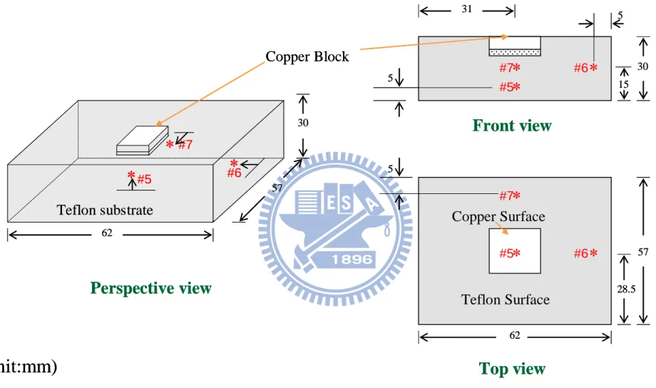
Fig. 2.2 Schematic diagram of the test heater assembly (not to scale). ---13 Fig. 2.3 Locations of three thermocouples in the copper block and one thermocouple
below the heater (not to scale). ---14 Fig. 2.4 Schematic diagram of placing strings on heating plate (not to scale). ---15
Fig. 3.1 Locations of three thermocouples in the Teflon substrate in order to
estimate heat loss (not to scale). ---23 Data Reduction
Fig. 4.1 Comparison of the present single-phase natural convection data with the empirical correlation of Radziemska and Lewandowski (2005). ---30 Saturated Pool Boiling Heat Transfer
Fig. 4.2 Comparison of the present nucleate boiling heat transfer data on smooth plate with Chang and You (1996). ---31 Fig. 4.3 Effects of string diameter on saturated pool boiling curves (a) and boiling heat
transfer coefficients (b) at hw=0mm and
w=10mm. ---32Fig. 4.4 Effects of string diameter on saturated pool boiling curves (a) and boiling heat transfer coefficients (b) at hw=0mm and
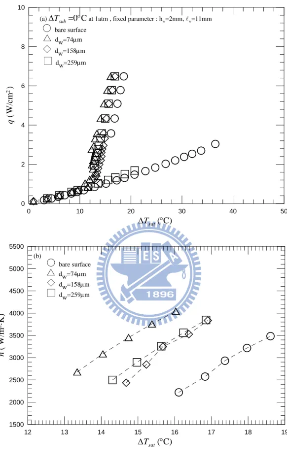
w=11mm. ---33Fig. 4.5 Effects of string diameter on saturated pool boiling curves (a) and boiling heat transfer coefficients (b) at hw=0mm and
w=12mm. ---34Fig. 4.6 Effects of string diameter on saturated pool boiling curves (a) and boiling heat transfer coefficients (b) at hw=1mm and
w=10mm. ---35Fig. 4.7 Effects of string diameter on saturated pool boiling curves (a) and boiling heat transfer coefficients (b) at hw=1mm and
w=11mm. ---36Fig. 4.8 Effects of string diameter on saturated pool boiling curves (a) and boiling heat transfer coefficients (b) at hw=1mm and
w=12mm. ---37Fig. 4.9 Effects of string diameter on saturated pool boiling curves (a) and boiling heat transfer coefficients (b) at hw=2mm and
w=10mm. ---38Fig. 4.10 Effects of string diameter on saturated pool boiling curves (a) and boiling heat transfer coefficients (b) at hw=2mm and
w=11mm. ---39Fig. 4.11 Effects of string diameter on saturated pool boiling curves (a) and boiling heat transfer coefficients (b) at hw=2mm and
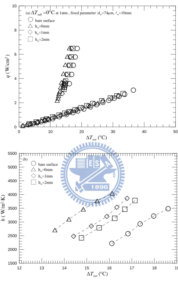
w=12mm. ---40Fig. 4.12 Effects of string height on saturated pool boiling curves (a) and boiling heat transfer coefficients (b) at dw=74μm and
w=10mm. ---41Fig. 4.13 Effects of string height on saturated pool boiling curves (a) and boiling heat transfer coefficients (b) at dw=74μm and
w=11mm. ---42Fig. 4.14 Effects of string height on saturated pool boiling curves (a) and boiling heat transfer coefficients (b) at dw=74μm and
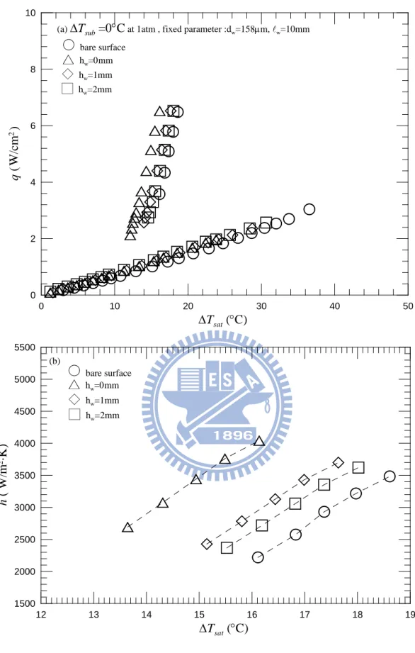
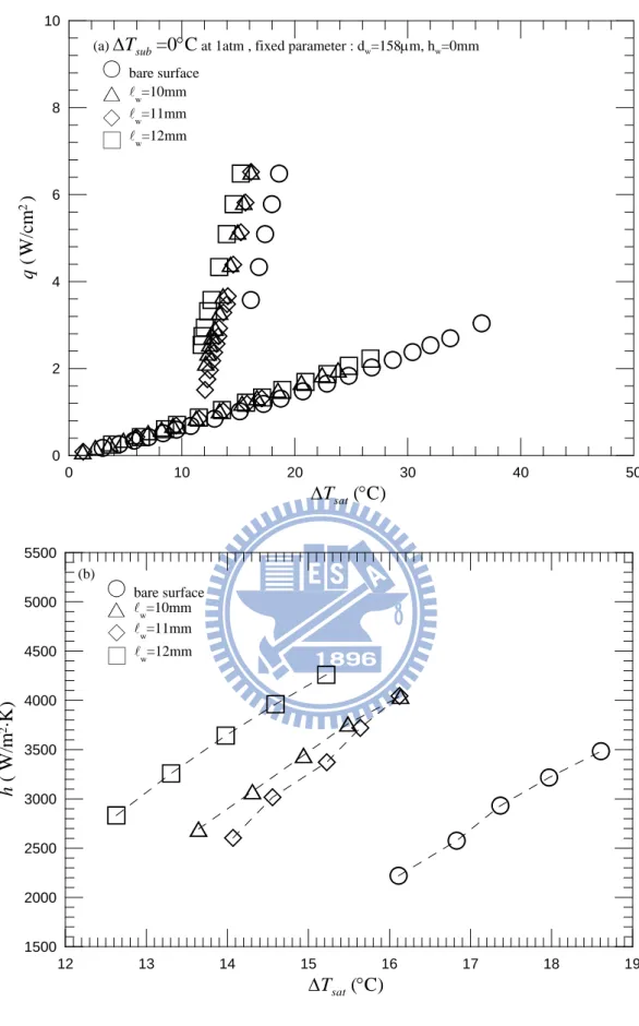
w=12mm. ---43Fig. 4.15 Effects of string height on saturated pool boiling curves (a) and boiling heat transfer coefficients (b) at dw=158μm and
w=10mm. ---44Fig. 4.16 Effects of string height on saturated pool boiling curves (a) and boiling heat transfer coefficients (b) at dw=158μm and
w=11mm. ---45Fig. 4.17 Effects of string height on saturated pool boiling curves (a) and boiling heat transfer coefficients (b) at dw=158μm and
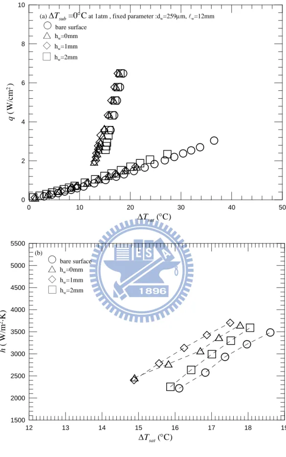
w=12mm. ---46Fig. 4.18 Effects of string height on saturated pool boiling curves (a) and boiling heat transfer coefficients (b) at dw=259μm and
w=10mm. ---47Fig. 4.19 Effects of string height on saturated pool boiling curves (a) and boiling heat transfer coefficients (b) at dw=259μm and
w=11mm. ---48Fig. 4.20 Effects of string height on saturated pool boiling curves (a) and boiling heat transfer coefficients (b) at dw=259μm and
w=12mm. ---49Fig. 4.21 Effects of string length on saturated pool boiling curves (a) and boiling heat transfer coefficients (b) at dw=74μm and hw
Fig. 4.22 Effects of string length on saturated pool boiling curves (a) and boiling heat transfer coefficients (b) at d
=0mm. ---50
w=74μm and hw
Fig. 4.23 Effects of string length on saturated pool boiling curves (a) and boiling heat transfer coefficients (b) at d
=1mm. ---51
w=74μm and hw
Fig. 4.24 Effects of string length on saturated pool boiling curves (a) and boiling heat transfer coefficients (b) at d
=2mm. ---52
w=158μm and hw
Fig. 4.25 Effects of string length on saturated pool boiling curves (a) and boiling heat transfer coefficients (b) at d
=0mm. ---53
w=158μm and hw
Fig. 4.26 Effects of string length on saturated pool boiling curves (a) and boiling heat transfer coefficients (b) at d
=1mm. ---54
w=158μm and hw
Fig. 4.27 Effects of string length on saturated pool boiling curves (a) and boiling heat transfer coefficients (b) at d
=2mm. ---55
w=259μm and hw
Fig. 4.28 Effects of string length on saturated pool boiling curves (a) and boiling heat transfer coefficients (b) at d
=0mm. ---56
w=259μm and hw
Fig. 4.29 Effects of string length on saturated pool boiling curves (a) and boiling heat transfer coefficients (b) at d
=1mm. ---57
w=259μm and hw
Fig. 4.30 Effects of string-string pitch on saturated pool boiling curves (a) and boiling heat transfer coefficients (b) at d
=2mm. ---58
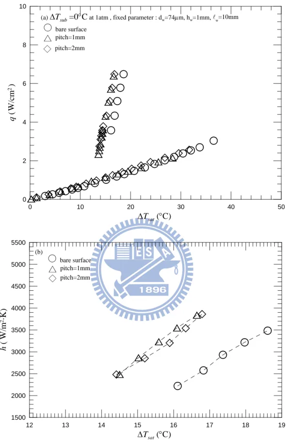
w=74μm, hw=1mm and
w=10mm. ---59Fig. 4.31 Effects of string-string pitch on saturated pool boiling curves (a) and boiling heat transfer coefficients (b) at dw=74μm, hw=1mm and
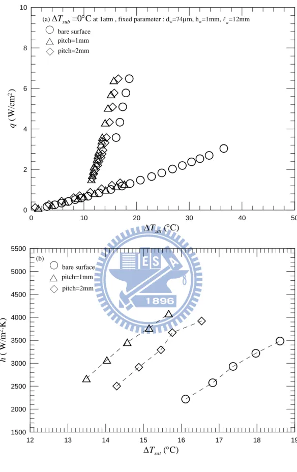
w=11mm. ---60Fig. 4.32 Effects of string-string pitch on saturated pool boiling curves (a) and boiling heat transfer coefficients (b) at dw=74μm, hw=1mm and
w=12mm. ---61Fig. 4.33 Effects of string-string pitch on saturated pool boiling curves (a) and boiling heat transfer coefficients (b) at dw=158μm, hw=1mm and
w=10mm. ---62Fig. 4.34 Effects of string-string pitch on saturated pool boiling curves (a) and boiling heat transfer coefficients (b) at dw=158μm, hw=1mm and
w=11mm. ---63Fig. 4.35 Effects of string-string pitch on saturated pool boiling curves (a) and boiling heat transfer coefficients (b) at dw=158μm, hw=1mm and
w=12mm. ---64Fig. 5.1 Present data of saturated and subcooled boiling curve. ---71 Subcooled Pool Boiling Heat Transfer
Fig. 5.2 Effects of string diameter on subcooled pool boiling curves (a) and boiling heat transfer coefficients (b) for ∆Tsub= 5°C at hw=0mm and
w=10mm. --72Fig. 5.3 Effects of string diameter on subcooled pool boiling curves (a) and boiling heat transfer coefficients (b) for ∆Tsub= 5°C at hw=0mm and
w=11mm. --73Fig. 5.4 Effects of string diameter on subcooled pool boiling curves (a) and boiling heat transfer coefficients (b) for ∆Tsub= 5°C at hw=0mm and
w=12mm. --74Fig. 5.5 Effects of string diameter on subcooled pool boiling curves (a) and boiling heat transfer coefficients (b) for ∆Tsub= 5°C at hw=1mm and
w=10mm. --75Fig. 5.6 Effects of string diameter on subcooled pool boiling curves (a) and boiling heat transfer coefficients (b) for ∆Tsub= 5°C at hw=1mm and
w=11mm. --76Fig. 5.7 Effects of string diameter on subcooled pool boiling curves (a) and boiling heat transfer coefficients (b) for ∆Tsub= 5°C at hw=1mm and
w=12mm. --77Fig. 5.8 Effects of string diameter on subcooled pool boiling curves (a) and boiling heat transfer coefficients (b) for ∆Tsub= 5°C at hw=2mm and
w=10mm. --78Fig. 5.9 Effects of string diameter on subcooled pool boiling curves (a) and boiling heat transfer coefficients (b) for ∆Tsub= 5°C at hw=2mm and
w=11mm. --79Fig. 5.10 Effects of string diameter on subcooled pool boiling curves (a) and boiling heat transfer coefficients (b) for ∆Tsub= 5°C at hw=2mm and
w=12mm. --80Fig. 5.11 Effects of string diameter on subcooled pool boiling curves (a) and boiling heat transfer coefficients (b) for ∆Tsub= 10°C at hw=0mm and
w=10mm. --81Fig. 5.12 Effects of string diameter on subcooled pool boiling curves (a) and boiling heat transfer coefficients (b) for ∆Tsub= 10°C at hw=0mm and
w=11mm. --82Fig. 5.13 Effects of string diameter on subcooled pool boiling curves (a) and boiling heat transfer coefficients (b) for ∆Tsub= 10°C at hw=0mm and
w=12mm. --83Fig. 5.14 Effects of string diameter on subcooled pool boiling curves (a) and boiling heat transfer coefficients (b) for ∆Tsub= 10°C at hw=1mm and
w=10mm. --84Fig. 5.15 Effects of string diameter on subcooled pool boiling curves (a) and boiling heat transfer coefficients (b) for ∆Tsub= 10°C at hw=1mm and
w=11mm. --85Fig. 5.16 Effects of string diameter on subcooled pool boiling curves (a) and boiling heat transfer coefficients (b) for ∆Tsub= 10°C at hw=1mm and
w=12mm. --86Fig. 5.17 Effects of string diameter on subcooled pool boiling curves (a) and boiling heat transfer coefficients (b) for ∆Tsub= 10°C at hw=2mm and
w=10mm. --87Fig. 5.18 Effects of string diameter on subcooled pool boiling curves (a) and boiling heat transfer coefficients (b) for ∆Tsub= 10°C at hw=2mm and
w=11mm. --88Fig. 5.19 Effects of string diameter on subcooled pool boiling curves (a) and boiling heat transfer coefficients (b) for ∆Tsub= 10°C at hw=2mm and
w=12mm. --89Fig. 5.20 Effects of string height on subcooled pool boiling curves (a) and boiling heat transfer coefficients (b) for ∆Tsub= 5°C at dw=74μm and
w=10mm. --90Fig. 5.21 Effects of string height on subcooled pool boiling curves (a) and boiling heat transfer coefficients (b) for ∆Tsub= 5°C at dw=74μm and
w=11mm. --91Fig. 5.22 Effects of string height on subcooled pool boiling curves (a) and boiling heat transfer coefficients (b) for ∆Tsub= 5°C at dw=74μm and
w=12mm. --92Fig. 5.23 Effects of string height on subcooled pool boiling curves (a) and boiling heat transfer coefficients (b) for ∆Tsub= 5°C at dw=158μm and
w=10mm. --93Fig. 5.24 Effects of string height on subcooled pool boiling curves (a) and boiling heat transfer coefficients (b) for ∆Tsub= 5°C at dw=158μm and
w=11mm. --94Fig. 5.25 Effects of string height on subcooled pool boiling curves (a) and boiling heat transfer coefficients (b) for ∆Tsub= 5°C at dw=158μm and
w=12mm. --95Fig. 5.26 Effects of string height on subcooled pool boiling curves (a) and boiling heat transfer coefficients (b) for ∆Tsub= 5°C at dw=259μm and
w=10mm. --96Fig. 5.27 Effects of string height on subcooled pool boiling curves (a) and boiling heat transfer coefficients (b) for ∆Tsub= 5°C at dw=259μm and
w=11mm. --97Fig. 5.28 Effects of string height on subcooled pool boiling curves (a) and boiling heat transfer coefficients (b) for ∆Tsub= 5°C at dw=259μm and
w=12mm. --98Fig. 5.29 Effects of string height on subcooled pool boiling curves (a) and boiling heat transfer coefficients (b) for ∆Tsub= 10°C at dw=74μm and
w=10mm. --99Fig. 5.30 Effects of string height on subcooled pool boiling curves (a) and boiling heat transfer coefficients (b) for ∆Tsub= 10°C at dw=74μm and
w=11mm. --100Fig. 5.31 Effects of string height on subcooled pool boiling curves (a) and boiling heat transfer coefficients (b) for ∆Tsub= 10°C at dw=74μm and
w=12mm. --101Fig. 5.32 Effects of string height on subcooled pool boiling curves (a) and boiling heat transfer coefficients (b) for ∆Tsub= 10°C at dw=158μm and
w=10mm. --102Fig. 5.33 Effects of string height on subcooled pool boiling curves (a) and boiling heat transfer coefficients (b) for ∆Tsub= 10°C at dw=158μm and
w=11mm. --103Fig. 5.34 Effects of string height on subcooled pool boiling curves (a) and boiling heat transfer coefficients (b) for ∆Tsub= 10°C at dw=158μm and
w=12mm. --104Fig. 5.35 Effects of string height on subcooled pool boiling curves (a) and boiling heat transfer coefficients (b) for ∆Tsub= 10°C at dw=259μm and
w=10mm. --105Fig. 5.36 Effects of string height on subcooled pool boiling curves (a) and boiling heat transfer coefficients (b) for ∆Tsub= 10°C at dw=259μm and
w=11mm. --106Fig. 5.37 Effects of string height on subcooled pool boiling curves (a) and boiling heat transfer coefficients (b) for ∆Tsub= 10°C at dw=259μm and
w=12mm. --107Fig. 5.38 Effects of string length on subcooled pool boiling curves (a) and boiling heat transfer coefficients (b) for ∆Tsub= 5°C at dw=74μm and hw
Fig. 5.39 Effects of string length on subcooled pool boiling curves (a) and boiling heat transfer coefficients (b) for ∆T
=0mm. ---108
sub= 5°C at dw=74μm and hw
Fig. 5.40 Effects of string length on subcooled pool boiling curves (a) and boiling heat transfer coefficients (b) for ∆T
=1mm. ---109
Fig. 5.41 Effects of string length on subcooled pool boiling curves (a) and boiling heat transfer coefficients (b) for ∆Tsub= 5°C at dw=158μm and hw
Fig. 5.42 Effects of string length on subcooled pool boiling curves (a) and boiling heat transfer coefficients (b) for ∆T
=0mm. ---111
sub= 5°C at dw=158μm and hw
Fig. 5.43 Effects of string length on subcooled pool boiling curves (a) and boiling heat transfer coefficients (b) for ∆T
=1mm. ---112
sub= 5°C at dw=158μm and hw
Fig. 5.44 Effects of string length on subcooled pool boiling curves (a) and boiling heat transfer coefficients (b) for ∆T
=2mm. ---113
sub= 5°C at dw=259μm and hw
Fig. 5.45 Effects of string length on subcooled pool boiling curves (a) and boiling heat transfer coefficients (b) for ∆T
=0mm. ---114
sub= 5°C at dw=259μm and hw
Fig. 5.46 Effects of string length on subcooled pool boiling curves (a) and boiling heat transfer coefficients (b) for ∆T
=1mm. ---115
sub= 5°C at dw=259μm and hw
Fig. 5.47 Effects of string length on subcooled pool boiling curves (a) and boiling heat transfer coefficients (b) for ∆T
=2mm. ---116
sub= 10°C at dw=74μm and hw
Fig. 5.48 Effects of string length on subcooled pool boiling curves (a) and boiling heat transfer coefficients (b) for ∆T
=0mm. ---117
sub= 10°C at dw=74μm and hw
Fig. 5.49 Effects of string length on subcooled pool boiling curves (a) and boiling heat transfer coefficients (b) for ∆T
=1mm. ---118
sub= 10°C at dw=74μm and hw
Fig. 5.50 Effects of string length on subcooled pool boiling curves (a) and boiling heat transfer coefficients (b) for ∆T
=2mm. ---119
sub= 10°C at dw=158μm and hw
Fig. 5.51 Effects of string length on subcooled pool boiling curves (a) and boiling heat transfer coefficients (b) for ∆T
=0mm. ---120
sub= 10°C at dw=158μm and hw
Fig. 5.52 Effects of string length on subcooled pool boiling curves (a) and boiling heat transfer coefficients (b) for ∆T
=1mm. ---121
sub= 10°C at dw=158μm and hw
Fig. 5.53 Effects of string length on subcooled pool boiling curves (a) and boiling heat transfer coefficients (b) for ∆T
=2mm. ---122
Fig. 5.54 Effects of string length on subcooled pool boiling curves (a) and boiling heat transfer coefficients (b) for ∆Tsub= 10°C at dw=259μm and hw
Fig. 5.55 Effects of string length on subcooled pool boiling curves (a) and boiling heat transfer coefficients (b) for ∆T
=1mm. ---124
sub= 10°C at dw=259μm and hw
Fig. 5.56 Effects of string string-string pitch on subcooled pool boiling curves (a) and boiling heat transfer coefficients (b) for ∆T
=2mm. ---125 sub= 5°C at dw=74μm, hw w
=1mm and =10mm. ---126 Fig. 5.57 Effects of string string-string pitch on subcooled pool boiling curves (a) andboiling heat transfer coefficients (b) for ∆Tsub= 5°C at dw=74μm, hw
w
=1mm and =11mm. ---127 Fig. 5.58 Effects of string string-string pitch on subcooled pool boiling curves (a) and
boiling heat transfer coefficients (b) for ∆Tsub= 5°C at dw=74μm, hw
w
=1mm and =12mm. ---128 Fig. 5.59 Effects of string string-string pitch on subcooled pool boiling curves (a) and
boiling heat transfer coefficients (b) for ∆Tsub= 5°C at dw=158μm, hw
w
=1mm and =10mm. ---129 Fig. 5.60 Effects of string string-string pitch on subcooled pool boiling curves (a) and
boiling heat transfer coefficients (b) for ∆Tsub= 5°C at dw=158μm, hw
w
=1mm and =11mm. ---130 Fig. 5.61 Effects of string string-string pitch on subcooled pool boiling curves (a) and
boiling heat transfer coefficients (b) for ∆Tsub= 5°C at dw=158μm, hw
w
=1mm and =12mm. ---131 Fig. 5.62 Effects of string string-string pitch on subcooled pool boiling curves (a) and
w
=10mm. ---132Fig. 5.63 Effects of string string-string pitch on subcooled pool boiling curves (a) and boiling heat transfer coefficients (b) for ∆Tsub= 10°C at dw=74μm, hw
w
=1mm and =11mm. ---133 Fig. 5.64 Effects of string string-string pitch on subcooled pool boiling curves (a) and
boiling heat transfer coefficients (b) for ∆Tsub= 10°C at dw=74μm, hw
w
=1mm and =12mm. ---134 Fig. 5.65 Effects of string string-string pitch on subcooled pool boiling curves (a) and
boiling heat transfer coefficients (b) for ∆Tsub= 10°C at dw=158μm, hw
w
=1mm and =10mm. ---135 Fig. 5.66 Effects of string string-string pitch on subcooled pool boiling curves (a) and
boiling heat transfer coefficients (b) for ∆Tsub= 10°C at dw=158μm, hw
w
=1mm and =11mm. ---136 Fig. 5.67 Effects of string string-string pitch on subcooled pool boiling curves (a) and
boiling heat transfer coefficients (b) for ∆Tsub= 10°C at dw=158μm, hw
w
=1mm and =12mm. ---137 Fig. 5.68 Photos of saturated pool boiling of FC-72 for various imposed heat flux of
bare surface. ---138 Fig. 5.69 Photos of subcooled pool boiling of FC-72 for ∆Tsub
imposed heat fluxes for bare surface. ---139 = 5°C for various
Fig. 5.70 Photos of subcooled pool boiling of FC-72 for ∆Tsub
imposed heat fluxes for bare surface. ---140 = 10°C for various
Fig. 5.71 Photos of subcooled pool boiling of FC-72 for ∆Tsub= 5°C at dw
w
=74μm, =11mm and hw=1mm. ---141
Fig. 5.72 Photos of subcooled pool boiling of FC-72 for ∆Tsub= 5°C at dw
w
=158μm, =11mm and hw
Fig. 5.73 Photos of subcooled pool boiling of FC-72 for ∆T
=1mm. ---142 sub= 5°C at dw w
=259μm, =11mm and hwFig. 5.74 Photos of subcooled pool boiling of FC-72 for ∆T
=1mm. ---143 sub= 10°C at dw w
=74μm, =11mm and hwFig. 5.75 Photos of subcooled pool boiling of FC-72 for ∆T
=1mm. ---144 sub= 10°C at dw w
=158μm, =11mm and hwFig. 5.76 Photos of subcooled pool boiling of FC-72 for ∆T
=1mm. ---145 sub= 10°C at dw w
=259μm, =11mm and hw=1mm. ---146NOMENCLATURE
A area, mm d 2 w h wire diameters, μm w w wire heightwire length
h heat transfer coefficient, W/m2
I measured current from DC power supply, A ·K k thermal conductivity, W/m·K L characteristic length, m NuL k hL NuL = Nusselt number, P system pressure, kPa Q heat transfer rate, W qn net wall heat flux, W/cm
Ra Rayleigh number, dimensionless
2
T temperature, ο
V measured voltage from DC power supply, V C
CHAPTER 1
INTRODUCTION
1.1 Motive of the Present Study
With the recent quick development of the microelectronic fabrication technology, the power dissipation density in various micro processors increases significantly. How to effectively remove the large amount of dissipating heat from the processors poses a great challenge to heat transfer research community. In order to transfer the large quantity of the dissipating heat from the chips with an ultra high component density, highly efficient heat transfer methods are required to control their temperatures at allowable level. Although air cooling is used commonly today, this method has reached its upper limit and is unable to solve the cooling problems encountered in the current electronics industry [1]. Therefore, alternate means of cooling based on liquid convection and liquid-vapor phase-change heat transfer have been considered. Among these, boiling heat transfer is regarded to be one of the most effective methods in electronics cooling comparing with the methods based on single-phase heat transfer because of the exchange of latent heat involved in the boiling processes. Methods to further improve the boiling heat transfer are therefore of great interest.
Over the past decades considerable effort has been devoted to investigating how the change in the heating surface structure can enhance the pool boiling heat transfer. The prominent examples include adding the micro-structures, pin fins and grooves to the surfaces. Besides, coating the surfaces with particles and covering the surfaces with screens have been known to be effective. These enhancement methods are based on various forms of extended surface fixed firmly onto the surfaces or directly fabricated on the surfaces. The possible pool boiling heat transfer enhancement by placing flexible and movable strings above the heating plate will be investigated in the present study. The strings are only fixed at their ends and
should be fine enough so that they can move to a certain extent near the surface by the forces induced in the boiling flow.
The working fluid FC-72, a dielectric fluorocarbon liquid manufactured by the 3M Company, is gaining popularity in electronics cooling application. It not only has suitable phase-change temperature for thermal control of I.C. components but also owns the quality that does not foul the boiling surface. More importantly, FC-72 has less impact on our environment than alternative liquids like chlorofluorocarbons or organic liquids. Copper has properties of better thermal conductivity than most metal and is often considered to be suitable for heat dissipating elements. Thus the heat transfer enhancement characteristics of pool boiling of the dielectric liquid on a copper plate by placing flexible strings above the heating surface immersed in FC-72 liquid are explored in the present stud y.
1.2 Literature Review
In what follows the literature relevant to the present study is briefly reviewed. Pool boiling heat transfer is a process of vigorous heat transfer resulting from latent heat exchange associated with liquid-to-vapor phase change in a quiescent liquid. Nukiyama [2] conducted a pioneering pool boiling experiment in 1934 and arranged the experimental heat transfer data as a form of the wall superheat versus the heat flux, which is known as the “boiling curve” today. After that, the pool boiling heat transfer research has received considerable attention.
The state of the art cooling technologies for handling heat dissipation in microelectronic equipments have been developed extensively over the past 30 years. Several products were released including Air-Cooled Modules, High Thermal Conduction Modules, and Liquid-Cooled Modules, as discussed by Bar-Cohen
In an early attempt to improve pool boiling heat transfer by using a micro-configured surface, Miller et al. [4] found that vapor retention could be a function of the scale and geometry of the micro-configurations.They pointed out that the relation between the stability
of the potential nucleation sites and the micro-configuration size and geometry required further investigation, so that the size and the site density of the cavities could be optimized for boiling heat transfer enhancement.
A few studies have been carried out to examine the influences of the surface fabricated microstructures on the pool boiling heat transfer. These include boiling of FC-72 on micro-porous surfaces with particle coating tested by Chang and You [5], adding microporous pin-fins and coating particles to the surface in the mean time investigated by Rainey and You [6] and by Rainey et al. [7], and fabricating micro-pin-fins and submicron-scale roughness on the surfaces by Honda et al. [8] and Wei et al. [9]. The study of Rainey and You [6] and Rainey et al. [7] concluded that the microporous coating can significantly enhance the boiling heat transfer performance over the pin-finned surfaces. In examining the pool boiling on the micro-pin-fin surfaces, Honda et al. [8] and Wei et al. [9] noted that the boiling curves were characterized by that a very small increase in the wall superheat can cause a large increase in the heat flux. And increasing the fin height was found to provide better heat transfer in the nucleate boiling regime and result in a higher critical heat flux. Anderson and Mudawar [10] reported that microstructures in the forms of fins, studs, grooves and vapor-trapping cavities on the boiling surface significantly shifted the boiling curve toward lower superheats while increasing the incipience excursion. Their results also suggest that the maximum boiling heat flux is a function of surface geometry and orientation but independent of the initial conditions, surface roughness, or the presence of large artificial cavities. Intending to augment boiling heat transfer, O’Connor and You [11] painted silver flakes on the boiling surface. Their experimental data show that the incipience boiling superheats are 70-85% lower and the nucleate boiling superheats are 70-80% lower than the bare surface. Besides the critical heat flux is increased by 109%. O’Connor et al. [12] then compared two methods of generating surface microstructures, “spraying” and “painting”, for pool boiling heat transfer enhancement. They noted that the incipient boiling superheat has 33-55% reduction for the sprayed alumina
and 63-85% reduction for the painted diamond. The enhancement in the critical heat flux can be up to 47% for the sprayed alumina and 103% for the painted diamond microstructures. Chang and You [13] further studied the effects of coating different sizes of the diamond particles on the pool boiling performances. They classified the coating thickness into two groups. For coatings thinner than 100μm, increasing the coating thickness would generate a higher active nucleation density. But for coatings thicker than 100μm, a further increase in the coating thickness does not always enhance the pool boiling heat transfer. They attributed this result to higher impedance for liquid-vapor exchange channels and higher thermal resistance for the thicker coating. Jung and Kwak [14] investigated the effects of submicron-scale roughness on the subcooled boiling heat transfer for a boiling surface anodized in DMF (dimethylforamide) and HF (hydrofluoric acid). Both surface treatments were found to increase the effective boiling area and serve for increasing the nucleation sites and hence show considerable enhancement in the boiling heat transfer. The critical heat flux also increases linearly. Honda and Wei [15] reviewed recent advances in enhancing boiling heat transfer from electronic components immersed in dielectric liquids through the use of surface microstructures and concluded that most of the surface microstructures were effective in decreasing the wall superheat at the boiling incipience. The nucleate boiling heat transfer also can be improved and the critical heat flux is raised. Rainey and You [16] and Rainey et al. [17] respectively studied the effects of the orientation and pressure on the pool boiling heat transfer from microporous surface. Their data show that nucleate boiling performance increases slightly for the surface inclined from 0ο(horizontal) to 45ο and then decreases for the inclination angle from 90ο to 180ο
Chou et al. [18] arranged several grooved patterns on surfaces intending to enhance boiling heat transfer of distilled water. Their experimental data reveal that the radial grooved
. Moreover, for the plain and microporous surfaces increases in boiling performance and critical heat flux and decrease in the incipience wall superheat were noted as the pressure increased.
pattern has the best enhanced boiling heat transfer performance and the spiral or concentric grooved pattern has poorer boiling heat transfer coefficient. The worst performance is noted for the grid or the spotted grooved pattern. All grooved patterns they investigated have better heat transfer performance than the plain surface and the denser groove is better than the sparser one for the same patterns.
Hasegawa et al. [19] covered a heat pipe with a woven screen to investigate the associated boiling characteristics and burnout phenomena. Their results disclose that the additional screen produces two opposite effects of inhibiting and enhancing the boiling heat transfer. Tsay et al. [20] explored pool boiling heat transfer enhancement by covering the boiling surface with a screen in distilled water. They found that the screen coverage could raise bubble generation frequency and enhance the boiling heat transfer. But the screen can also cover some nucleation sites and hence may retard the boiling heat transfer. They also noted that the boiling heat transfer decreased at lowering the liquid level. They concluded that covering the heated surface with a screen can augment the pool boiling heat transfer if the mesh size is comparable with the bubble departure diameter. In boiling of methanol and HFE-7100, Liu et al. [21] pointed out that placing a fine mesh layer on the boiling surface enhances nucleate boiling heat transfer at low wall superheat (∆T<10K) but an opposite trend results at a high superheat (∆T>10K). They also reported that the heat transfer in nucleate boiling always becomes worse with a coarse mesh on the boiling surface when compared with that on a smooth surface. Moreover, Franco et al. [22] used dielectric refrigerant R141b to investigate enhancement in the boiling heat transfer performance by covering the heated surface with wire meshes. The boiling heat transfer coefficient was noted to increase significantly, especially at relatively low heat fluxes. They also found that the wire mesh coverage on the heating surface results in slower transition to steady film boiling. In studying the effects of the wall superheat and the mesh layer covering on boiling heat transfer, Kurihara and Myers [23] tested several working fluids including water, acetone, n-hexane, carbon
tetrachloride, and carbon disulfide. They found that active nucleation sites on the heating plate increased due to the mesh covering and the boiling heat transfer coefficient was proportional to the one-third power of the bubble column numbers at high numbers.
1.3 Objective of Present Study
The above literature review clearly reveals that considerable works have been carried out in the past to investigate the enhancement in the pool boiling heat transfer over a surface by using the surface microstructures such as roughness, micro-pin-fins, mesh screens, and particle coating. All these microstructures are fixed firmly onto the boiling surface. In this study, an experimental study is conducted to explore the possible enhancement in the FC-72 pool boiling heat transfer by placing flexible and movable fine wires above the boiling surface. The wires are loosely fixed at their two ends on the surface and hence are allowed to move adjacent to the heating surface during the boiling processes to some degree. This movement of the wires adjacent to the boiling surface is expected to greatly affect the bubble dynamics near the surface and hence the boiling heat transfer from the surface. Besides, in the present study we will also examine the associated bubble behavior in the boiling flow by visualizing the flow. Both the possible saturated and subcooled pool boiling heat transfer enhancement will be examined.
7
CHAPTER 2
EXPERIMENTAL APPARATUS AND PROCEDURES
A schematic arrangement of the experimental apparatus for the present investigation of the pool boiling heat transfer enhancement by flexible strings is shown in Fig. 2.1. The experimental system includes a main test chamber, a test heater assembly, and other auxiliary parts such as a D.C. power supply, a data acquisition unit and a high-speed photographic unit. The working fluid, FC-72, is a highly wetting dielectric fluorocarbon liquid produced by 3M Industrial Chemical Products Division, which has been considered as a good candidate fluid for liquid immersion cooling applications. It is chemically stable, dielectric, and has a relatively low boiling point (Tsat=56°C at atmospheric pressure). Some thermophysical properties of
FC-72 are given in Table 2.1.
2.1 Main Test Chamber
The main test chamber is a hermetic stainless steel pressure vessel of 205mm in height and 216mm in diameter. An internal water condenser is installed inside the chamber and connects with a thermostat (LAUDA RK20) to maintain the bulk temperature of the working fluid in the chamber at the preset level. The maximum cooling power of the thermostat is 200W (at 20°C). We further use an external temperature controller (FENWAL MYSPEC Digital Temperature Controller) to control the bulk temperature of FC-72 in the test chamber with an accuracy of
±0.1°C. Besides, a cartridge heater is located near the bottom of the test chamber to provide additional heating during the degassing process. In order to prevent the heat loss from the vessel to the ambient, a superlon layer of 10-mm thick is wrapped
8
around the chamber. Moreover, a pressure transducer with an operating range of 0-980kPa is located at the gate valve to measure the pressure of the work fluid. Meanwhile, the working fluid temperature is measured by two resistance temperature detectors (RTDs) located at the gate valve and at a selected location 5cm above the bottom surface of the chamber with a calibrated accuracy of ± 0.1°C. An auxiliary tank of 10-liter liquid FC-72 is placed right above the test vessel and it is only used for subcooled pool boiling experiment to prevent regassing of the working fluid after degassing. A pressure transducer and a RTD are placed in the auxiliary tank to measure the internal gas pressure and liquid temperature. In addition, a test heater assembly is mounted to a stainless steel shelf to fix the Teflon substrate. The working fluid is maintained at approximately 80mm above the heated surface in the experiment.
2.2 Test Heater Assembly
A schematic of the test heater assembly is shown in Fig. 2.2. The assembly consists mainly of a film heater and is adhered to a square copper block with epoxy Omegabond 200 . The heater supplies the required power input to the copper block. The copper block is flush mounted onto a much larger Teflon block. Liquid FC-72 boils on the upper surface of the copper block and its side is 10-mm long. More specifically, the copper block is heated by the D.C. current delivered from the film heater adhering to the lower surface of the copper block. Besides, three calibrated copper-constantan thermocouples (T-type) with a calibrated accuracy of ±0.2°C are installed at selected locations in the copper block right below the boiling surface. They are used for the control and determination of the boiling surface temperature. The detailed locations of the thermocouples are shown in Fig. 2.3. Note that the whole
9
copper block is inserted into a Teflon block which serves as a heat insulator (kT ≈0.35W/m⋅K) intending to reduce the heat loss from the lateral and bottom surfaces of the block to the ambient.
2.3 Installation of Strings on Boiling Surface
The strings are fixed on the upper surface of the copper block by paste at their ends, as schematically shown in Fig. 2.4. The nylon threads are chosen in the present experiment because of its good flexibility. Specifically, each the nylon thread has the same mean diameter.The nylon strings are installed uniformly at the same pitch and height above the heating surface. Besides, the vertical distance between the strings and boiling surface will be varied in the test to investigate its effects on the pool boiling heat transfer. Moreover, the looseness of the strings measured by their length relative to the length of the boiling surface on the boiling heat transfer will be investigated. The measured data apparently will be compared with that of a bare heating surface (without the presence of the strings).
2.4 DC Power Supply
The power generated in the film heater in the test heater assembly is provided by a programmable D.C. power supply (Chroma 6203-15). It offers a maximum D.C. power of 300W for an output voltage of 15V and an output current of 20A. The power input to the copper block is transmitted through a GPIB interface to a personal computer. In order to measure the D.C. current, a precision ammeter (KYORITSU A.C./D.C. DIGITAL CLAMP METER) is arranged in series connection with the electric circuit. Besides, a YOKOGAWA data recorder is used to measure the voltage drop across the test heater assembly. All the voltage, current and power measurement
10
devices are calibrated by a YOKOGAWA WT200 power meter according to the Center of Measurement Standards in Industrial Technology Research Institute of Taiwan.
2.5 Data Acquisition
A 30-channel YOKOGAWA data recorder (MX-100) combined with a personal computer is used to acquire and process the data from various transducers. All signals detected from the T-type thermocouples, RTDs, pressure transducer, ammeter, data recorders and power meter are all collected and converted by the internal calibration equations in the computer during the data acquisition.
2.6 Experimental Procedures
Prior to putting all the devices and components for the experimental system together, the boiling surface is polished by fine sand paper (Number 3000) and cleaned by alcohol. In each test, we need to remove the non-condensable gases in the empty test chamber by running a vacuum pump for about 15 minutes and then fill the FC-72 liquid into the test chamber. Next, the FC-72 liquid in the test chamber is heated to the saturation state by employing a digital temperature controller and cartridge heater. Moreover, the FC-72 liquid is boiled vigorously for 2 hours to remove the dissolved noncondensible gases in it. After the working fluid pressure and temperature stabilize to one atmosphere and at the saturation state, we turn on the test heater. The imposed heat flux on the boiling surface is adjusted by controlling the electric current delivered to the heater from the D.C. power supply. Upon reaching the statistical state, we begin collecting the required heat transfer data and visualizing the boiling activity.
11
Table 2.1 Thermophysical properties of FC-72.
Properties at 25οC FC-72
Appearance Clear, colorless Average Molecular Weight 338
Boiling Point (1atm) 56°C
Pour Point (1atm) -90°C
Estimated Critical Temperature 449K Estimated Critical Pressure 1.83 × 10⁶ Pa
Vapor Pressure 3.09 × 10⁴ Pa Latent Heat of Vaporization hfg 88 J/g
(at normal boiling point)
Liquid Density ρ 1680 kg/m3
Absolute Viscosity µ 6.4× 10⁻³ poises ; 6.4× 10⁻⁴ kg/m∙s Kinematic Viscosity ν 3.8 × 10⁻³ stokes ; 3.8 × 10⁻⁷ m2/ s Liquid Specific Heat cp 1100 J/kg∙°C
Liquid Thermal Conductivity k 0.057 W/m∙°C Coefficient of Expansion β 0.00156 /°C
12 Liquid Level
P
Condenser Coil Observation WindowTo Degassing Tank and Drain
Computer GPIB MX100 Data Acquisition Heater Boiling Surface FC-72 Digital Temperature Controller Shelf RTD Condenser Test Heater Assembly Observation Window Electric Cord Signal Cord Programmable D.C. Power Supply Liquid Level
P
Condenser Coil Observation WindowTo Degassing Tank and Drain
Computer GPIB MX100 Data Acquisition Heater Boiling Surface FC-72 Digital Temperature Controller Shelf RTD Condenser Test Heater Assembly Test Heater Assembly Observation Window Electric Cord Signal Cord Programmable D.C. Power Supply
13 62 30 10 3 1 10
(unit:mm)
Teflon substrate
Front view
Top view
30 62 57Embedded Copper Block
Electric Film Heater
Copper Surface
Teflon Surface
Perspective view
57Conductive Pastes
62 30 10 3 1 10(unit:mm)
Teflon substrate
Front view
Top view
30 62 57Embedded Copper Block
Electric Film Heater
Copper Surface
Teflon Surface
Perspective view
57
Conductive Pastes
14
Front view
Perspective view
(unit:mm)
∗
#1Top view
∗
#2∗
#3 2 3 3 2 0.3∗
#1∗
#2 #4∗
#3 5Copper Surface
Copper Block
Electric Film Heater
Conductive Pastes
∗
∗
∗
10 5 3 1 10 #1 #2 #3∗
#4 #4∗
4Front view
Perspective view
(unit:mm)
∗
#1Top view
∗
#2∗
#3 2 3 3 2 0.3∗
#1∗
#2 #4∗
#3 5Copper Surface
Copper Block
Electric Film Heater
Conductive Pastes
∗
∗
∗
10 5 3 1 10 #1 #2 #3∗
#4 #4∗
4Fig. 2.3 Locations of three thermocouples in the copper block and one thermocouple below the heater (not to scale).
15
Teflon substrate
Flush-mounted Copper Block
(unit:mm)
Strings
62 57 30Teflon substrate
Flush-mounted Copper Block
(unit:mm)
Strings
62
57 30
CHAPTER 3
DATA REDUCTION
3.1 Boiling Heat Transfer Coefficient
The space-average boiling heat transfer coefficient over the upper surface of the heated square copper block at long time when the flow is at a statistical state is defined as sat n T q h= Δ (3.1) where qn is the net heat flux imposed on the upper surface andΔTsat
× − = Cu n Cu w k δ q T T is the wall superheat defined as the difference between the average surface temperature and the saturated temperature of FC-72. The average heated surface temperature is estimated from the measured average temperature from the thermocouples installed at locations near the upper surface of the copper block according to the steady-state one-dimensional conduction heat transfer. Specifically,
(3.2)
where TCu
k
= the average measured temperature from the thermocouples (°C)
Cu
δ
= the thermal conductivity of copper (W/m·K)
= the vertical distance between the thermocouple tips and the upper surface of the copper block (m)
The total power input Qt to the copper block can be obtained from the voltage
drop across the film heater in the test heater assembly and the current passing through it,
V I
Qt = ⋅ (3.3)
where Qt
I = electric current passing through the film heater (Amp.)
= total power input to the upper surface of the copper block (W)
V = voltage drop across the film heater (Volts)
In fact, the Teflon insulator cannot completely prevent the heat loss from the surfaces of the copper block. Heat loss across the insulator does exist, mainly from the lateral sides of the copper block and heater and from the bottom of the heater. The heat loss is estimated by one-dimensional heat conduction in the Teflon insulator and convection from the insulator surface to the ambient based on a model schematically shown in Fig. 3.1. Thus, we have
(
)
(
)
(
)
7 7 7 , 7 6 6 6 , 6 5 5 5 , 5 1 2 1 2 1 h k L A T T h k L A T T h k L A T T Q T T sur T T sur T T sur loss + − ⋅ + + − ⋅ + + − = (3.4) where Tsur T: the ambient temperature (°C)
5 , T6 , T7
k
: the average measured temperatures at the measured locations inside the Teflon insulator, as schematically shown in Fig. 3.1
T
L
: thermal conductivity of the Teflon insulator (W/m·K)
5 , L6 , L7
A
: shortest distances between locations #5, #6, #7 and the insulator surfaces (m)
T,5 , AT,6 , AT,7 : bottom and lateral surface areas of the Teflon block
hi : estimated natural convection heat transfer coefficient from the Teflon block
surfaces to the surroundings by correlations from Incropera et al. [24]. (W/m2 2 7 , 2 6 , 2 5 , mm 2 62 30 , mm 2 57 30 , mm 2 57 62× = × = × = T T T A A A ·K)
h5 4 / 1 L L 0.27Ra Nu =
: estimated from for the bottom surface of the Teflon block.
h6 , h7
(
)
[
9/16]
4/9 4 / 1 L L Pr / 492 . 0 1 Ra 670 . 0 68 . 0 Nu + + =: estimated from for the lateral surfaces of
the Teflon Block.
Finally, the net imposed input heat flux to the upper surface of copper square can be evaluated from the relation
Cu loss t n A Q Q q = − (3.5) where ACu is the area of the upper surface of the copper block.
3.2 Uncertainty Analysis
An uncertainty analysis is carried out here to estimate the uncertainty levels in the experiment. Kline and McClintock [25] proposed a formula for evaluating the uncertainty in the result F as a function of independent variables, X1, X2,
X3···Xn
F=F (X ,
1 ,X2, X3···Xn
The absolute uncertainty of F is expressed as
) (3.6) 2 1 2 2 3 3 2 2 2 2 1 1 ∂ ∂ + + ∂ ∂ + ∂ ∂ + ∂ ∂ = n n X X F X X F X X F X X F F δ δ δ δ δ (3.7)
and the relative uncertainty of F is
2 1 2 2 3 3 3 2 2 2 2 2 1 1 1 ∂ ∂ + + ∂ ∂ + ∂ ∂ + ∂ ∂ = n n n X X nX nF X X nX nF X X nX nF X X nX nF F F δ δ δ δ δ (3.8)
If F =X1aX2bX3c... , then the relative uncertainty is 2 1 2 3 3 2 2 2 2 1 1 + + + = X X c X X b X X a F F δ δ δ δ (3.9) where i X F ∂ ∂
and ∂ are, respectively, the sensitivity coefficient and uncertainty Xi
level associated with the variableX . The values of the uncertainty intervalsi ∂ are Xi
obtained by a root-mean-square combination of the precision uncertainty of the instruments and the unsteadiness uncertainty, as recommended by Moffat [26]. The choice of the variableX to be included in the calculation of the total uncertainty i level of the result F depends on the purpose of the analysis.
The uncertainties of the parameters in the present study are calculated as follows: (1) Uncertainty of temperature difference, ∆Tsat=Tw-T
(
)
(
)
2 1 2 2 2 1 2 2 2 1 2 2 ) ( ) ( − + − = − + − = ∂ − ∂ + ∂ − ∂ = − − sat w sat sat w w sat sat sat w sat w w sat w w sat sat sat sat w w w w sat w sat w sat w T T T T T T T T T T T T T T T T T T nT T T n T T nT T T n T T T T δ δ δ δ δ δ δ sat (3.10) (2) Uncertainty of total power input, QV I Qt = ⋅ t (3.3) and 2 1 2 2 + = V V I I Q Q t t δ δ δ (3.11)
(3) Uncertainty of net wall heat flux, q Cu loss t n A Q Q q = − e (3.5) and 2 1 2 2 2 2 1 2 2 2 2 1 2 2 2 1 − + − + = − + − + ⋅ = ∂ ∂ + ∂ ∂ + ∂ ∂ = loss t loss loss t t Cu Cu loss loss loss t loss t t loss t t Cu Cu loss loss loss n t t t n Cu Cu Cu n n n Q Q Q Q Q Q A A Q Q Q Q Q Q Q Q Q Q A A Q Q nQ nq Q Q nQ nq A A nA nq q q δ δ δ δ δ δ δ δ δ δ (3.12) where
(
)
(
)
(
)
7 7 7 , 7 6 6 6 , 6 5 5 5 , 5 1 2 1 2 1 h k L A T T h k L A T T h k L A T T Q T T sur T T sur T T sur loss + − ⋅ + + − ⋅ + + − = (3.4)(4) Uncertainty of space-average heat transfer coefficient, h
sat n T q h= Δ (3.1) and
(
)
(
)
2 1 2 2 2 1 2 2 2 1 2 2 1 1 − − + = − − ⋅ + ⋅ = − − − ∂ ∂ + ∂ ∂ = sat w sat w n n sat w sat w n n sat w sat w sat w n n n T T T T q q T T T T q q T T T T T T n nh q q nq nh h h δ δ δ δ δ δ δ (3.13) A summary of the results from the present uncertaintly analysis is given in Table 3.1.
Table 3.1 Summary of the results from the uncertainty analysis.
Parameter Uncertainty
Geometry Length & thickness (%)
Area (%) ± 0.5% ± 1.0% Parameter measurement Temperature, T (°C) Temperature difference (°C)
System pressure, P (kPa)
± 0.2 ± 0.4 ± 0.5 Boiling heat transfer on the copper flat plate Power input, Qt
Imposed effective heat flux, q (%)
n
Heat transfer coefficient, h (%) ± (%) 8.2% ± 14.8% ± 13.4%
Perspective view
Front view
30 62 57Copper Surface
Teflon Surface
Teflon substrate
62 57 30∗
#5 #7∗
#6∗
Top view
∗
#7 #5∗
#6∗
5(unit:mm)
5 5 31 15 28.5 #6∗
∗
#5∗
#7Copper Block
Perspective view
Front view
30 62 57Copper Surface
Teflon Surface
Teflon substrate
62 57 30∗
#5 #7∗
#6∗
Top view
∗
#7 #5∗
#6∗
5(unit:mm)
5 5 31 15 28.5 #6∗
∗
#5∗
#7Copper Block
CHAPTER 4
SATURATED POOL BOILING HEAT TRANSFER ENHANCEMENT OF
FC-72 OVER A SMALL HEATED HORIZONTAL COPPER SURFACE
The experimental results for the possible enhancement of saturated pool boiling heat transfer of FC-72 by placing flexible strings above the heating surface measured in the present study are examined in this chapter. The present experiments are carried out for the diameter of the nylon strings varied from 74 to 259 μm, the height of the strings from 0 to 2 mm, and the length of the strings from 10 to 12 mm for the pitch of the strings mainly fixed at 2.0 mm with the FC-72 liquid in the test chamber maintained at saturated liquid state corresponding to the atmospheric pressure. The measured data are presented in terms of the boiling curves and boiling heat transfer coefficients for various diameters, heights, length of the flexible strings and for a bare heating surface. Effects of the experimental parameters on the possible boiling heat transfer enhancement will be examined in detail. Selected results are presented in the following to illustrate the possible pool boiling heat transfer enhancement by the flexible strings.
4.1 Single-phase Natural Convection Heat Transfer
Before conducting the pool boiling experiment, we first measure steady natural convection heat transfer over the heated small copper surface without the installation of the strings which prevails at low imposed heat flux, intending to verify the present experimental setup. The measured data for the natural convection heat transfer coefficient are compared with the empirical correlation of Radziemska and Lewandowski [27] in Fig. 4.1. Their correlation is
where w is the width of the heating plate (m). The correlation given in Eq.(4.1) is based on the data for a small horizontal plate heated from below for 105<RaL<108
(4.2) . Note that the characteristic length L used in defining the dimensionless groups in the above equation is chosen to be the ratio of the heated surface area and its perimeter, and the Nusselt and Rayleigh numbers are respectively defined as
and
(4.3) The results in Fig. 4.1 indicate that our natural convection data are in good agreement with that calculated from Eq. (4.1). Thus the experimental system established here is considered to be suitable for the present study.
4.2 Saturated Pool Boiling on Bare Copper Surface
To further verify the suitability of the present experimental facility, the boiling curve for saturated pool boiling of FC-72 on a bare heated copper surface is also obtained. These data are compared with those from Chang and You [28] for pool boiling of FC-72 on a small square copper plate of 1cm2 in surface area in Fig. 4.2. The results indicate that the present data are in qualitative agreement with those of Chang and You [28] before and after the onset nucleate boiling.
4.3 Effects of String Diameter on Boiling Heat Transfer Enhancement
Attention is then turned to examining how the diameter of the flexible strings affects the boiling heat transfer of FC-72 on the heated plate. This is illustrated in Figs. 4.3-4.11 by showing the boiling curves and the variations of the boiling heat transfer coefficients with the wall superheat for various string diameters at different string heights and lengths. The results for the boiling curves clearly indicate that the presence of the flexible strings significantly reduces the temperature overshoot at the
k hL NuL = αν β 3 L )L ( Ra = g ∆Tsat
onset of boiling and hence the boiling hysteresis. Besides, the inception of the boiling takes place at a much lower wall superheat with the strings installed. It is also noted that at the same wall superheat ΔTsat the boiling heat transfer coefficients are
substantially higher for the surface covered by the strings for certain dw,wand hw
when compared with that for the bare heated surface, as clearly seen by checking with the data for the variations of the heat transfer coefficient with ΔTsat. These data show
that an increase in the boiling heat transfer coefficient of more than 100% over that for a bare heated surface by placing the flexible strings on the heating surface can be obtained. Note that at a smallΔTsat the boiling heat transfer coefficient is already
relatively high for the plate covered with the strings but the flow over the bare surface is still in single-phase state. Moreover, the extent of the boiling heat transfer enhancement varies nonmonotonically with size, looseness and height of the strings. This is attributed to the complex effects of these parameters on the bubble dynamics in the boiling flow. A close inspection of these data reveals that when the strings directly contact the heating surface ( hw
w
=0mm ) and the strings are tightly fixed at their ends ( =10mm), placing the strings with the largest diameter of 259μm results in the highest heat transfer enhancement ( Fig. 4.3 ). While for the strings with dw
w
=74μm & 158μm the enhancements are somewhat smaller and nearly the same. Note that for the strings being slightly loose at =11mm the heat transfer enhancement for the three different string size do not differ significantly with each other, as evident from the data given in Fig. 4.4. The boiling heat transfer coefficient is enhanced by about 60 to 80%. But for the strings loosened substantially at = 12w
mm the data in Fig.4.5 show that the boiling heat transfer is noticeably better for the smaller strings. At dw
Now when the strings are installed at a slightly higher position with h
=74μm a boiling heat transfer coefficient enhancement of more than 100% can be procured.
w=1mm