694 CHIEN-YUAN PAN, JEN-YEA JAN, LIANG-CHIN WANG, COMPACT AND BROADBAND MICROSTRIP-LINE-FED MODIFIED …
Compact and Broadband Microstrip-Line-Fed
Modified Rhombus Slot Antenna
Chien-Yuan PAN,
Jen-Yea JAN, Liang-Chin WANG
Dept. of Electronic Engineering, National Kaohsiung University of Applied Sciences, Kaohsiung 80778, Taiwan cypan@cc.kuas.edu.tw
Abstract. The printed microstrip-line-fed broadband
rhombus slot antenna is investigated in this paper. With the use of the offset microstrip feed line and the corner-trun-cated protruded ground plane, the bandwidth enhancement and the slot size reduction for the proposed slot antenna can be obtained. The experimental results demonstrate that the impedance bandwidth for 10 dB return loss reaches 5210 MHz (108.2%, 2210-7420 MHz), which is about 2.67 times of a conventional microstrip-line-fed rhombus slot antenna. This bandwidth can provide with the wireless communication services operating in wireless local area network (WLAN) and worldwide interoperability for micro-wave access (WiMAX) bands. Under the use of the pro-truded ground plane, the slot size can be reduced by about 52%. Details of simulated and measured results are pre-sented and discussed.
Keywords
Rhombus slot antenna, protruded ground plane, WLAN/WiMAX.
1. Introduction
Various printed slot antennas are used for broadband applications because they have attractive characteristics such as wide impedance bandwidth, low cost and planar structure. In addition, they are easy to be integrated with active devices. In recent years, some microstrip-line-fed printed slot antennas [1-5] were reported because of their favorable broadband performances. In [5], a printed slot antenna with a fork-like tuning stub was proposed to achieve a bandwidth enhancement. However, the structure of microstrip feed line in [5] makes the antenna configura-tion more complicated. Another printed microstrip-line-fed slot antenna with a simple rotated slot for a wider band-width was suggested in [6]. As a result, a wide operating bandwidth of about 2200 MHz (48.9%) with respect to the center frequency at 4500 MHz was obtained. However, it is not enough for the impedance bandwidth to cover more operating bands for wireless communication services. In fact, most of wireless communication systems require
miniaturized antennas for practical applications. It leads to much attention to reduce the slot size in antenna design.
In recent years, some techniques of compact slot antennas were reported by [7-13]. These antennas have many advantages individually but having their limitations. In [7-9], it is seen that both slot antenna and feed line struc-tures are apparently complex. In [10-11], the small-size tapered slot antennas use a rectangular cut in the microstrip feed line in [10] and a transformer for the transmission-line impedance matching in [11]. Both antenna designs exhibit that the complicated microstrip feed line is used to achieve broadband operation. According to [12-13], antenna struc-tures with meander and folded slots were investigated. But they also lead to the problem of great complexity in an-tenna design and fabrication. Recently, new slot anan-tennas such as using an L-shaped strip line in the modified bow-tie slot antenna with a rectangular tuning stub [14] or a coplanar waveguide (CPW)-fed rhombus slot antenna with a rhombic ring feeding structure and rectangular bulge components [15] were proposed for dual-band operation.
In the previous study [16], we presented a microstrip-line-fed rhombus slot antenna with a pair of parasitic strips for the wideband operation. By embedding a pair of para-sitic elements in this design, the slot antenna has an imped-ance bandwidth of 4290 MHz (108.7%). In order to achieve the operating bandwidth as large as [16], the com-pact broadband modified rhombus slot antenna is proposed and investigated in this paper. By using simple shifting the microstrip feed line and embedding the corner-truncated protruded ground plane, the modified rhombus slot antenna for broadband operation and slot size reduction can be realized.
2. Antenna Designs
Fig. 1 shows the evolution of the proposed micro-strip-line-fed rhombus slot antenna. According to [6], a structure of rhombus-shaped slot is selected as shown in Fig. 1(a). For the operating frequency at around 4 GHz suitable for WLAN/WiMAX applications, the rhombus slot with the side length of 25 mm is printed on an FR4 sub-strate with thickness of 1.6 mm and relative permittivity r
RADIOENGINEERING, VOL. 22, NO. 3, SEPTEMBER 2013 695
of 4.4. Note that the rhombus slot as indicated in Fig. 1(a) has a mean circumference of 50 mm, which is correspond-ing to approximately 1.1λ at the operatcorrespond-ing frequency of 4 GHz, where λ is the wavelength at the operating fre-quency given by0/ (1r)/2, with being λ0 the free
space wavelength. In order to achieve a wider operating bandwidth, a straight microstrip line with an offset distance is used as shown in Fig. 1(b). The distance is only 1 mm from the vertices of the rhombus slot to the ground plane so that this antenna has the size of 37.4 mm × 54 mm.
Fig. 1. Evolution of the proposed printed rhombus slot antenna.
Note that four antennas in Fig. 1(a) to (d) are all fed by the 50 Ω microstrip line with a length of LS, which is printed on the opposite side of the FR4 substrate. For de-sign simplicity, the width of the tuning stub is chosen to be the same to the 50 Ω microstrip feed line. In order to re-duce the rhombus slot size, a protrusion of ground plane from one of rhombus sides is embedded as shown in Fig. 1(c) and 1(d). The protruded ground plane used for miniaturizing the slot size in Fig. 1(c) has a rectangular strip of L × W mm2. In order to improve the impedance
bandwidth of Fig. 1(c), the use of the corner-truncated protruded ground plane in Fig. 1(d) has a rectangular trun-cation (L1 × W1 mm2) near the corner of microstrip line.
Simulated results from the aid of the 3D full-wave high frequency structure simulator (HFSS) indicate that the
proper offset distance of microstrip feed line and dimen-sions of the proper corner-truncated protruded ground plane can enhance the antenna’s operating bandwidth to operate at lower frequency. Then the proposed compact slot antenna with the improved impedance bandwidth can be achieved. In the following section, the parameter’s study for the proposed antenna is presented in detail.
3. Studied Results and Discussions
In this study, experimental results of impedance band-width, radiation pattern, and gain are presented. The Agi-lent 8722ES network analyzer was used to measure the re-turn loss. For the far-field performances, the NSI-800F-10 anechoic chamber was used for measurements of antenna’s radiation pattern and gain.
Tab. 1. The performance of impedance bandwidth in Fig. 1(b) with various offsets of d and LS.
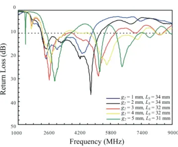
Fig. 2. Measured return loss against frequency of the pro-posed antenna in Fig. 1(c) with various values of g2
and LS as g1 = 1 mm, d = 5 mm, LS = 32 mm, W = 21 mm and L = 20 mm. (The same Tab. 2 shown).
Typically, a rhombus slot antenna such as Fig. 1(a) rotated from a square slot as suggested in [6] can provide a wideband operation with an impedance bandwidth about 40.5% as shown in Tab. 1 (as d = 0 mm). In order to excite a wider impedance bandwidth, an offset microstrip feed line is used in Fig. 1(b). By selecting the proper offset
d (mm) LS (mm) Center Frequency f C (MHz) BW (MHz, %) 0 (conventional) 34 4000 (3190-4810) 1620, 40.5 3 34 4335 (3210-5460) 2250, 51.9 4 34 4470 (3230-5710) 2480, 55.5 5 35 4950 (3130-6770) 3640, 73.5 6 35 5310 (3360-7260) 3900, 73.4 7 35 5435 (3420-7450) 4030, 74.1
RADIOENGINEERING, VOL. 22, NO. 3, SEPTEMBER 2013 699
References
[1] YOSHIMURA, Y. A microstrip line slot antenna. IEEE Trans.
Microwave Theory Tech., 1972, vol. 20, p. 760-762.
[2] AXELROD, A., KISLIUK, M., MAOZ, J. Broadband microstrip-fed slot radiator. Microwave J., Jun. 1989, p. 81–94.
[3] TAM, W. Y. Microstripline-fed cylindrical slot antenna. IEEE
Trans. Antennas Propagat., 1998, vol. 46, p. 1587-1589.
[4] KAHRIZI, M. T., SARKAR, K., MARICEVIC, Z. A. Analysis of a wide radiating slot in the ground plane of a microstrip line. IEEE
Trans. Microwave Theory Tech., 1993, vol. 41, p. 29-37.
[5] SZE, J. Y., WONG, K. L. Bandwidth enhancement of a microstrip-line-fed printed wide-slot antenna. IEEE Trans. Antennas
Propagat., 2001, vol. 49, p. 1020-1024.
[6] JAN, J. Y., SU, J. W. Bandwidth enhancement of a printed wide-slot antenna with a rotated wide-slot. IEEE Trans. Antennas Propagat., 2005, vol. 53, p. 2111-2114.
[7] WANG, C. J., LEE, J. J., HUANG, R. B. Experimental studies of a miniaturized CPW-fed slot antenna with the dual-frequency operation. IEEE Antennas and Wireless Propagat. Lett., 2003, vol. 2, p. 151-154.
[8] LUI, W. J., CHENG, C. H., ZHU, H. B. Compact frequency notched ultra-wideband fractal printed slot antenna. IEEE
Microwave and Wireless Components. Lett., 2003, vol. 16, no. 4,
p. 224-226.
[9] TANG, I. T., LIN, D. B., LIOU, G. H., HORNG, J. H., LI, C. M. A compact slot UWB antenna with CPW-fed. In IEEE Antennas
and Propagation International Symposium, June 2007, p. 5143 to
5146.
[10] GOPIKRISHNA, M., KRISHNA, D. D., AANANDAN, C., MOHANAN, K. P., VASUDEVAN, K. Compact linear tapered slot antenna for UWB applications. Electron. Lett., 2008, vol. 44, no. 44, p. 1174-1175.
[11] VERBIEST, J. R., VANDENBOSCH, G. A. E. Low-cost small-size tapered slot antenna for lower band UWB applications.
Electron. Lett., 2006, vol. 42, no. 12, p. 670-671.
[12] KIM, H., YOON, Y. J. Compact microstrip-fed meander slot antenna for harmonic suppression. Electron. Lett., 2003, vol. 39, no. 10, p. 761-763.
[13] AZADEGAN, R., SARABANDI, K. Bandwidth enhancement of miniaturized slot antennas using folded, complementary, and self-complementary relations. IEEE Trans. Antennas Propagat., 2007, vol. 55, no. 9, p. 2435-2444.
[14] YOON, J. H., LEE, Y. C. Modified bow-tie slot antenna for the 2.4/5.2/5.8 GHz WLAN bands with a rectangular tuning stub.
Microw. Opt. Technol. Lett., 2011, vol. 53, no. 1, p. 126–130.
[15] LIN, C. C., YU, E. Z., HUANG, C. Y. Dual-band rhombus slot antenna fed by CPW for WLAN applications. IEEE Antennas and
Wireless Propagat. Lett., 2012, vol. 11, p. 362-364.
[16] JAN, J. Y., WANG, L. C. Printed wideband rhombus slot antenna with a pair of parasitic strips for multiband applications. IEEE
Trans. Antennas Propagat., 2009, vol. 57, no. 4, p. 1267-1270.
About Authors
Chien-Yuan PAN was born in Kaohsiung, Taiwan. He
received the B.S. degree in Electronic Engineering from National Taiwan University of Science and Technology, Taipei, Taiwan, in 1991, and the M.S. and Ph.D. degrees in Electrical Engineering from National Sun Yat-sen Univer-sity, Kaohsiung, Taiwan, in 1996 and 2007, respectively. In 1992 he joined the Department of Electronic Engineer-ing, National Kaohsiung University of Applied Sciences, Kaohsiung, Taiwan, and is currently an assistant professor. His research interests are in microwave printed antennas and passive component designs.
Jen-Yea JAN was born in Kaohsiung, Taiwan. He
received the bachelor's degree in Electronic Engineering from National Ocean University, Keelung, Taiwan in 1980, the master degree in Communication Engineering from National Chiao Tung University, Hsinchu, Taiwan in 1983, and the Ph.D. degree from National Sun Yat-Set Univer-sity, Kaohsiung, Taiwan in 2000. Since 1985, he has been with the Department of Electronic Engineering at the Na-tional Kaohsiung University of Applied Sciences, Kaohsi-ung, Taiwan. Now, he is a professor. His current research interests are in microstrip antenna theory, small printed antennas for wireless communications systems, printed ultra-wideband antennas and electromagnetic wave propagation.
Liang-Chin WANG was born in Kaohsiung, Taiwan. He
received the M.S. degree in Electronic Engineering from National Kaohsiung University of Applied Sciences, Kaohsiung, Taiwan, in 2009. His research interests are in planar slot antenna designs.