A Verification-Aware Design Methodology for Thread Pipelining Parallelization
9
0
0
全文
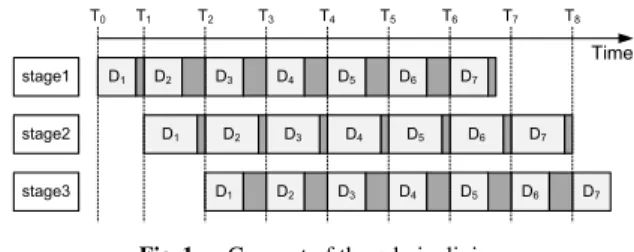
(2) IEICE TRANS. INF. & SYST., VOL.E95–D, NO.10 OCTOBER 2012. 2506. stages. Generally, parallel programming is complicated and error-prone [3]. Therefore, despite the numerous benefits that thread pipelining can offer, it remains problematic to reliably verify the correctness of an application parallelized by this approach. Many previous studies have considered verification issues related to parallel programming. Previous verification approaches can be roughly classified into two types: mathematical and formal verifications. We briefly describe these approaches as follows: (1) Mathematical approach: A parallel program can be described and modeled by a sequence of formal statements. According to the theorem proving and induction principles, we can mathematically verify whether a parallel program is correct [4], [5]. (2) Formal verification: The target design is modeled through a modeling language such as UML (Unified Modeling Language) [6]–[9]. Then, the designer can verify the target design by using verification tools. In recent years, behavior-modeling techniques have been widely used in several research areas, including the verification of embedded systems [10], [11], and hardware– software co-design [12]–[15]. According to the concept of behavior-modeling techniques, a behavior model is introduced as a bridge between an original program and the parallel program, for the purpose of verification. It also serves as a firewall that appropriately prevents the bugs caused in the design stage from spreading to the implementation stage during the parallelization. In this paper, we propose a verification-aware methodology to help developers to correctly parallelize applications by using thread pipelining. Replacing traditional verification approaches that directly verify parallel programs, the proposed methodology divides the development of a parallel program into the behavior and parallel phases. In the behavior phase, the original program is appropriately transformed into the corresponding behavior-model program, which sequentially executes and mimics the actions of the final parallelized program. In the parallel phase, the parallel program is intuitively derived from the behavior-model program. The proposed methodology has the advantage of integrating verification mechanisms into the design flow. During verification, the behavior-model program is concurrently executed with the original program or its parallel program to automatically verify the results. To demonstrate the practicality of the proposed methodology, we applied it to the parallelization of a 3D depth map generator with thread pipelining. The parallel 3D depth map generator was further integrated into a 3D video playing system for evaluation of the verification overheads of the proposed methodology and the system performance. The results show the parallel system achieved 33.72 fps in D1 resolution and 12.22 fps in HD720 resolution through a five-stage pipeline. When verifying the parallel program, the proposed verification approach keeps the performance degradation within 21% and 22% in D1 and HD720 resolutions, respectively.. 1.1. Contribution. This paper makes the following contributions: (1) Verification methodology: A verification-aware design methodology is presented that helps programmers to identify program bugs and to develop correct parallel programs. Compared to the existing formal verification and mathematical researches, it has the following advantages: (a) Low learning threshold for beginners. The proposed methodology does not rely on any metalanguages (formal specification languages) or software tools for the verification. It has a lower learning threshold, so developers can easily perform the program parallelization and verification. (b) No statespace explosion. For the formal verification and mathematical approach, programs to be verified are modeled by metalanguages or are formally specified by mathematical formulas. Then state machines are used to simulate for the verification. The state-space explosion might occur due to the enormous increment of the number of states in parallel programs. The proposed methodology uses behavior-model programs to replace the detailed state simulation. (c) Low risk of starting again from scratch. The existing verification researches only focus on the verification which is one of the last stages during software development. If developers find bugs which are resulted from design errors, they will be forced to go back to the design stage to re-design the parallel programs. This situation will significantly hurt software development productivity. The proposed methodology integrates the design and verification flows of program parallelization into a standard operation procedure (SOP). By using the proposed methodology, developers are forced to face the verification at the design stage, and the software productivity and reliability of developing parallel programs can be improved according to software engineering literatures. The proposed methodology also suffers two overheads. First, the behavior-model program used in the proposed methodology is required to be verified. Then the verified behavior-model program is used to help the verification of the parallel program. Although developers need to do the verification of the behavior-model program, they can thoroughly understand the behavior of the parallel program during the verification. This experience can help developers to efficiently construct the parallel program. Second,the proposed methodology does not aim to prove total correctness of parallel programs. Its goal is to quickly find out most of the bugs while parallelizing sequential programs and to build up workable parallel programs. For critical systems, developers need to perform deductive verification in order to guarantee the total correctness of software components. (2) Case study: The feasibility and practicality of the proposed methodology is demonstrated by applying the approach to developing a parallel 3D depth map generator, which is further integrated into a 3D video playing system for evaluation of the verification overheads of the proposed methodology and the system performance. The experimen-.
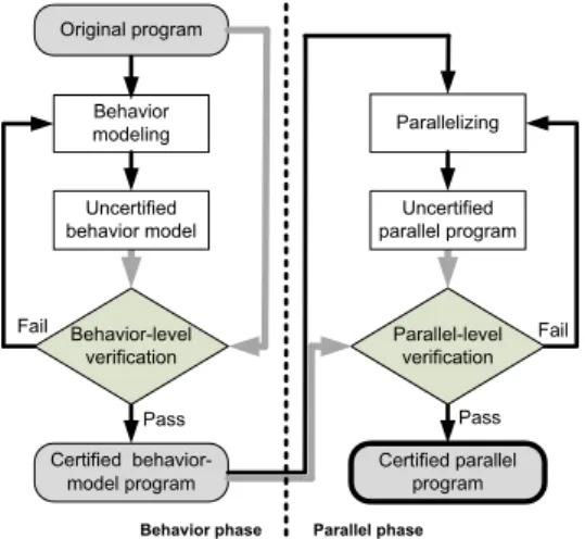
(3) JIAN et al.: A VERIFICATION-AWARE DESIGN METHODOLOGY FOR THREAD PIPELINING PARALLELIZATION. 2507. tal results are presented, showing an improvement in the performance of the 3D video playing system and in the verification overheads of the proposed methodology. The remainder of this paper is organized as follows. Section 2 presents the proposed verification-aware design methodology, and Sect. 3 describes how to apply the proposed verification mechanism to a parallel 3D depth map generator, and reports the results of simulations and performance measurements. Finally, the conclusions are presented in Sect. 4. 2.. Verification-Aware Methodology. Generally, for the parallelization of applications, developers intuitively rewrite the sequential program into the corresponding parallel version using techniques in which they are skilled. However, this approach carries a high risk of errors. In addition, developers may encounter problems during debugging, even though they can quickly parallelize the program using their advanced coding skills. In contrast to the traditional design procedures, we propose a verificationaware methodology to help developers to correctly parallelize applications by using thread pipelining. Figure 2 shows the whole design flow that is used to parallelize an application with the proposed verification-aware methodology. Of note, the verification mechanisms are integrated into the design flow. We leverage a behavior-model program as a bridge for gradually and correctly parallelizing the original program. The proposed methodology divides the development of the parallel program into the behavior and parallel phases. In the behavior phase, the original program is appropriately transformed into the corresponding behaviormodel program, which sequentially executes and mimics the actions of the final parallelized program. To prevent the construction of an incorrect behavior model, behaviorlevel verification is performed to ensure consistency in functionalities between the original program and the behaviormodel program. After building the certified behavior-model program, we enter the parallel phase, in which developers. Fig. 2. Design flow of the proposed verification-aware methodology.. start to construct the parallel program based on the certified behavior-model program, and parallel-level verification is performed to fix bugs in the parallel program. Below, we describe how to model the behaviors of pipelining execution, and we provide detailed descriptions of behavior- and parallel-level verification. 2.1. Behavior Model. The behavior model plays an important role during the process of parallelization because it is a bridge that helps to reduce the coding complexity when directly writing parallel programs from sequential programs. The construction of a behavior-model program involves three steps. The first step is data packetization. For thread pipelining parallelization, data transfer among pipeline stages is usually a major source of synchronization problems. During this step, all the related data required by pipeline stages are appropriately grouped into a packet that is delivered among the pipeline stages to simplify the construction of a pipeline and to avoid redundant interference. Figure 3 shows a pseudo code that demonstrates the technique of data packetization. Assume func1()–funcn() perform the orderly processing of a stream of data. The original program uses shared data to communicate among func1()–funcn(), as shown on the left side of Fig. 3; the program that uses data packets is shown on the right side of the figure. A structure data type, PACKET, can be appropriately defined to form a data packet that contains the necessary data for func1()–funcn(). func1()–funcn() are also suitably modified to operate on the data packets. The second step in the construction of a behaviormodel program is task partitioning, which decides the number of stages in the pipeline. According to the pattern of thread-pipelining, the entire computation must be divided into several tasks so that all the tasks can concurrently operate on different data. These tasks conceptually represent the stages in the pipeline. The workload of each task should be balanced in order to maximize the performance of the whole pipeline. Figure 4 shows a pseudo code that partitions the original works, func1()–funcn(), into m stages: behavior stage1()–behavior stagem(). The third step is behavior pipelining, which involves the construction of a behavior-model program to sequentially and faithfully simulate the execution of the pipeline built by the final parallelized program. Here, we focus on. Fig. 3. Pseudo code at the step of data packetization..
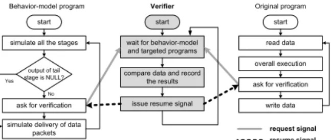
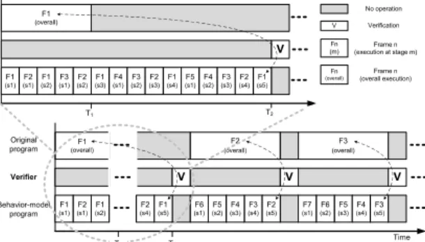
(4) IEICE TRANS. INF. & SYST., VOL.E95–D, NO.10 OCTOBER 2012. 2508. Fig. 6 Fig. 4. Fig. 7. 2.2.1. Fig. 5. Working flow of behavior-level verification.. Pseudo code at the step of task partitioning.. Pseudo code at the step of behavior pipelining.. the behavior of the pipeline. To mimic the pipeline execution, we add several statements to control the execution of the stages. Each function no longer performs its computation over the same data packet, and the loop iteration has to be changed to N stage + (Ntotal − 1), where N stage is the number of stages in the pipeline and Ntotal is the number of input data. Figure 5 shows the pseudo code at the step of behavior pipelining for the case shown in Fig. 4. 2.2 Verification Here, we describe the verification mechanisms that are integrated into the proposed verification-aware methodology. As shown in the rhombuses in Fig. 2, the verification process is required to perform during the behavior and parallel phases. The behavior-level verification assesses the consistency of functionalities between the behavior-model and the original programs, and the parallel-level verification assesses the consistency of functionalities between the behavior-model and parallel programs. To improve the practicability, the behavior- and parallel-level verifications are run synchronously, which means that the behavior-model program is concurrently executed with the original program or parallel program to automatically verify the results. This strategy results in a much higher likelihood of identifying bugs in the application.. Timing diagram of behavior-level verification.. Behavior-Level Verification. Figure 6 shows the workflow of behavior-level verification. The behavior-model program is set as the target to be verified, and the original program is set as a comparison that provides reliable data for verification. During the behaviorlevel verification, the original program does not process the next data until it has finished processing the current data. Therefore, verification is not started until the first processed data have passed completely through the pipeline. A verifier routinely waits for request signals from the behavior-model and original programs, compares data, records the results of comparisons and status information, and issues resume signals back to the behavior-model and original programs. Figure 7 shows a timing diagram in which it is assumed that the original program, the behavior-model program, and the verifier are executed by individual threads. An overall execution on data n represents the execution of all pipeline-related computations regarding these data. For the case shown on the right-hand side of Fig. 3, the pipeline-related computations are func1()–funcn(). At timestamp T 1 , the original program finishes the overall execution on the data D1 ; meanwhile, the data D1 are processed at stage2 for the behaviormodel program. The verifier must wait until the behaviormodel program completes the process on D1 . At timestamp T 2 , the behavior-model program completes the process on D1 and then the verifier is signaled to start verifying the current results. After finishing the verification, the original and behavior-model programs resume processing the next data. 2.2.2. Parallel-Level Verification. For simplicity, we assume that the parallel program contains a pipeline with several pipeline workers. Each pipeline worker is dedicated to one pipeline stage, and each pipeline.
(5) JIAN et al.: A VERIFICATION-AWARE DESIGN METHODOLOGY FOR THREAD PIPELINING PARALLELIZATION. 2509. stage can be only assigned to one pipeline worker. Because the mapping between physical processor cores and pipeline workers is flexible, this assumption does not result in any loss of generality for the approach. Figure 8 shows the workflow of parallel-level verification. The parallel program is set as the target to be verified, and the certified behaviormodel program is set as a comparison that provides reliable data for verification. The verifier and behavior-model program are concurrently executed with all pipeline workers. When a pipeline worker finishes the work on one data packet, it pauses the execution and issues a request signal to the verifier. Similarly, the behavior-model program simulates the behavior of pipeline execution. Given that the data packets from all pipeline stages must be verified, the verifier may spend a lot of time checking the data. If the verifier focuses on the parts where data are written-out, the efficiency of the checking data is significantly improved. Figure 9 shows a timing diagram for parallel-level verification. At timestamp T 1 , the pipeline work1 finishes work on D1 , and as does the behavior-model program. The verifier starts the verification and then issues the resume signal. Next, due to parallel execution, pipeline worker1 and pipeline worker2 finish work on D2 and D1 before the behavior-model program finishes the same work. Therefore, the verifier is required to wait and cannot start the verification until timestamp T 2 . 2.3 Software Design Change Here we describe the issues relating to software design change. When the design of data packets or pipeline stages is changed, developers should go through the proposed design flow again in order to ensure the correctness of functionality of parallel programs. For these cases, developers should re-write the behavior-model program and then per-. Fig. 8. Fig. 9. form behavior-level verification to get a certified behaviormodel program. Then developers have to re-construct the parallel program based on the revised behavior model. Finally parallel-level verification should be performed to check consistency of functionality between the behavior model and parallel programs. Although developers should go through the proposed design flow when the design of data packets or pipeline stages is changed, it does not mean everything has to be re-done. The efforts about thread management and synchronization can be completely reused. In addition, the development experience can be passed down to reduce software development time and related cost. 3.. Case Study. In this section, we present a case study in which the proposed verification-aware methodology is used to help to efficiently and correctly parallelize a 3D depth map generator. The parallel 3D depth map generator is then integrated into a 3D video playing system to demonstrate its capability. 3.1. 3D Depth Map Generator. Figure 10 shows the depth map generation algorithm [16], which generates depth maps from single 2D images. The algorithm can operate on three types of input images: images of general scenes with a vanishing point (VP), images of scenery containing sky and mountains, and close-up images. First, the algorithm classifies input images into three categories. Images containing few vanishing lines are identified as close-up images; those containing a sufficient number of vanishing lines are classified as general images; and those containing a sufficient number of vanishing lines, as well as sky and mountains, are classified as scenery images. The following techniques are used to generate accurate depth maps: edge detection using Sobel filtering, line detection using a 5 × 5 Hough transform, vanishing region detection, segmentation, depth map merging, depth map postprocessing by simplified joint bilateral filtering (SJBF), and block-based contrast filtering for identifying foreground objects in close-up images. These processing steps are also optimized to reduce the computational complexity while re-. Working flow of parallel-level verification.. Timing diagram of parallel-level verification.. Fig. 10. Depth map generation algorithm..
(6) IEICE TRANS. INF. & SYST., VOL.E95–D, NO.10 OCTOBER 2012. 2510. Fig. 11. Structure of the 3D video playing system.. Fig. 13 Timing diagram of behavior-level verification for the 3D depth map generator.. Fig. 12. Task partition for the 3D depth map generator.. Fig. 14 erator.. Concept of parallel-level verification for the 3D depth map gen-. taining high image quality. Figure 11 shows the structure of the 3D video playing system, which consists of a video dispatcher, a 3D depth map generator, and a pseudo display. The video dispatcher reads the decoded video and then splits it into several individual frames that are in order dispatched to the 3D depth map generator to produce the corresponding depth map information. Finally, the pseudo display collects all the information in order and completes the work. 3.2 Parallelization We now explain how to parallelize the 3D depth map generator by using the proposed verification-aware design methodology. Our target is to leverage thread-pipelining parallelization to develop a parallel 3D depth map generator. According to the proposed design flow, we first start work in the behavior phase to construct a behavior-model program corresponding to the parallel 3D depth map generator. In addition to arranging the processed data and temporal buffers into suitable data packets, the workload distribution of the 3D depth map generator is analyzed in order to select an appropriate number of pipeline stages in the parallel program. After considering the issue of workload balance and the dependence relationships among operations in the generator, the generator is partitioned into five stages, S 1 ∼ S 5 , as shown in Fig. 12. Next, we implement the behavior-model program and perform behavior-level verification to ensure the behavior-model program can correctly mimic the behaviors of the parallel program. Figure 13 shows the timing diagram of the behavior-level verification for the 3D depth map generator. The behavior-model program, verifier, and original 3D depth map generator are concurrently executed through individual threads. After repeated modification and verification, we construct a certified behavior-model program. For a developer who is familiar with the proposed. Fig. 15 Timing diagram of parallel-level verification for the 3D depth map generator.. verification-aware design methodology and the original 3D depth map generator program, it would take about 1 day to develop the certified behavior-model program. During the behavior phase, most of the coding time is spent modeling the pipeline behavior. Next, we enter the parallel phase to develop the parallel 3D depth map generator. Figure 14 shows the concept of synchronous verification during parallel-level verification. The behavior-model program, verifier, and parallel program are concurrently executed to test the results generated from each pipeline stage. Figure 15 shows the timing diagram of the parallel-level verification for the development of the parallel 3D depth map generator. It takes 8 days to complete the parallel depth map generator from the certified behavior-model program. For the parallel phase, we spent most of the coding time handling the communications among pipeline stages. The design of the synchronization mechanism among threads is also time-consuming. 3.3. Evaluation and Discussion. Table 1 lists the configuration of the experimental environment. The experiments were evaluated on a multicore platform with eight processors, each of which is an.
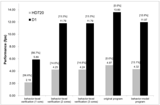
(7) JIAN et al.: A VERIFICATION-AWARE DESIGN METHODOLOGY FOR THREAD PIPELINING PARALLELIZATION. 2511 Table 1 Hardware. Configuration of the experimental environment. Item CPU. Cache. Software. Memory Operating system Native C compiler Thread library. (a) Performance comparison. Value 8 quad-core processors, and each processor is AMD Opteron quadcore running at 2.3 GHz L1: 64 KB/core, L2: 512 KB/core, L3: 2 MB/processor 64 GB Linux (kernel version: 2.6.31) GCC 3.4.6 with “-O2” option POSIX thread library. Fig. 17. Performance comparison of the behavior-level verification.. Fig. 18. Performance comparison of the parallel-level verification.. (b) Speedup comparison. Fig. 16 Comparison of performance and speedup for the evaluated configuration.. AMD Opteron quad-core processor running at 2.3 GHz. The 3D depth map generator was verified on 303 tested cases that contain images and videos with resolutions of HD720 (1280x720) and D1 (720x480). The tested cases are randomly selected and fed into the 3D depth map generator during the verification. Figure 16 (a) compares the performance of the various programs for the evaluated configuration, and Fig. 16 (b) shows speedup values with the original program as a baseline for comparison. The original 3D video playing system can achieve 4.97 fps in HD720 resolution and 13.60 fps in D1 resolution. The behavior-model program of the 3D video playing system sequentially simulates the pipeline execution, and several control statements are added in the program to maintain the behavior of the pipeline execution. Therefore, it can only achieve 4.32 fps in HD720 resolution and 11.97 fps in D1 resolution, and the speedup is 0.87 in HD720 resolution and 0.88 in D1 resolution. With the help of thread-pipelining parallelization, the processing speed of the parallel system can achieve 12.22 fps in HD720 resolution, and 33.72 fps in D1 resolution, corresponding to speedup of the parallel system compared with the original program of 2.46 and 2.48, respectively. In addition to evaluating the original, behavior-model, and parallel programs, we also test the performance of the 3D video playing system during the verification, in order to understand the impact of the synchronous verification overheads on performance. The behavior-level verification uses three threads to respectively execute the original, behaviormodel, and verifier programs. The parallel-level verification uses five threads to execute the parallel program which is parallelized by a five-stage thread pipelining. Besides, it also uses one thread to execute the behavior-model pro-. gram and one thread to execute the verifier program. Figure 17 and Fig. 18 show the performance comparison of the behavior-level and parallel-level verifications. In the figures, the labels “behavior-level verification (X cores)” and “parallel-level verification (X cores)” on the x-axis represent the performance during the behavior-level and parallel-level verifications, respectively. X represents how many cores are used to execute the behavior-level and parallel-level verifications. The y-axis represents the performance in fps. The number in the square brackets indicates the performance degradation with the original program as a baseline for comparison, while the number below the square brackets indicates the performance. Consider the relationship between the performance of behavior-level verification and the number of cores available to the verification, as shown in Fig. 17. For the case that three cores available to execute the behavior-level verification, the performance degradation caused by verification is 14.6% in HD720 resolution and 13.3% in D1 resolution. The performance of behavior-level verification executed on two cores is slightly slower than that on three cores. The reason is the execution time of the verifier program is much smaller than the original or behavior-model programs. Consider the relationship between the performance of parallel-level verification and the number of cores available to the verification, as shown in Fig. 18. For the case that seven cores available to execute the parallel-level verification, the performance degradation caused during the.
(8) IEICE TRANS. INF. & SYST., VOL.E95–D, NO.10 OCTOBER 2012. 2512 Table 2. Comparison of code size.. program original program behavior-model program parallel program code size 654,978 705,621 710,303 (bytes). Table 3. Description of programs bugs identified during verification.. Behavior phase. Parallel phase. Description of errors Forget to give the data-bufferrelated variables initial values. Read/write wrong data buffers due to coding error. Declare wrong data type during data packetization. Data access error due to access an invalid address. Deliver data packets to wrong threads. Synchronization error due to two threads concurrently access the same data buffer. Errors due to globally synchronize among threads (pipeline workers).. Difficulty Easy Easy Medium Medium Medium Hard. Hard. parallel-level verification is 21.1% and 23% for HD720 and D1 resolutions, respectively. The results indicate that the verification overhead brought by the proposed synchronous verification mechanism is affordable and reasonable. The evaluation also shows the performance of parallel-level verification is proportional to the number of cores available to the verification. Table 2 lists the code size of static linked executables for the original, behavior-model, and parallel programs. Several program bugs were identified during the verification. Table 3 provides a description of the serious errors that arose during system development. In the behavior phase, most of the errors resulted from the process of rewriting the original 3D depth map generator to the corresponding behavior-model program. Because most of the work on data packetization and task partitioning was performed in the behavior phase, most of the errors in the parallel phase arose from synchronization among threads (pipeline workers). The term “Difficulty” in Table 3 is used to represent the efforts of finding the errors. Compared to the behavior phase, most of the synchronization errors in the parallel phase are difficult to be found. The reason is that the occurrence of such errors may depend on some execution order of threads and the execution of the threads may proceed out of order. 4.. Conclusion. We proposed a verification-aware design methodology that provides developers with a systematic and reliable approach to performing thread-pipelining parallelization on sequential programs, especially large or complicated programs. In contrast to the traditional design flow, a behavior-model program is constructed before parallelization as a bridge to help developers gradually leverage the technique of thread-. pipelining parallelization. The characteristics of pipelining mean that construction of the behavior-model program is straightforward and much less error-prone than other design patterns of parallel programs. To verify the behavior-model program, a synchronous verification approach is proposed, whereby the original program is concurrently executed with the behavior-model program to automatically verify the results. After creating a certified behavior-model program, a parallel program can be constructed based on the behaviormodel program. Employing an approach similar to synchronous verification, the behavior-model program is concurrently executed with the parallel program to test the correctness of parallel program. This strategy has a high likelihood of identifying bugs. To demonstrate the practicality of the proposed methodology, it was applied to parallelize a 3D depth map generator using thread pipelining. The parallel 3D depth map generator was further integrated into a 3D video playing system for evaluation of the verification overheads of the proposed methodology and the system performance. The results show the parallel system can achieve 33.72 fps at D1 resolution and 12.22 fps at HD720 resolution through a five-stage pipeline. When verifying the parallel program, the proposed approach of synchronous verification keeps the performance degradation within 23% and 21.1% for D1 and HD720 resolutions, respectively. The proposed methodology can help developers to rectify bugs and to overcome the complexity of developing parallel programs by employing a verification-aware design flow. For leveraging the thread-pipelining execution model, this technique not only reduces the risks of problems arising when directly parallelizing a sequential program, it also provides a standard operation procedure (SOP) for designing a reliable parallel program on multicore systems. Acknowledgement This work was sponsored by the National Science Council of Taiwan under grants NSC-98-2220-E-194-014 and NSC-99-2221-E-194-048. The authors are grateful to the National Center for High-Performance Computing for computer time and facilities. References [1] T. Mattson, B. Sanders, and B. Massingill, Patterns for parallel programming, first ed., Addison-Wesley Professional, 2004. [2] W. Thies, V. Chandrasekhar, and S. Amarasinghe, “A practical approach to exploiting coarse-grained pipeline parallelism in C programs,” Proc. 40th Annual IEEE/ACM International Symposium on Microarchitecture, MICRO 40, Washington, DC, USA, pp.356–369, 2007. [3] P. Pacheco, An Introduction to Parallel Programming, 1st ed., Morgan Kaufmann Publishers, San Francisco, CA, USA, 2011. [4] G.R. Andrews, “Parallel programs: proofs, principles, and practice,” Commun. ACM, vol.24, pp.140–145, March 1981. [5] R.M. Keller, “Formal verification of parallel programs,” Commun. ACM, vol.19, pp.371–384, July 1976. [6] C. Larman, Applying UML and Patterns: An Introduction to ObjectOriented Analysis and Design and Iterative Development (3rd Edition), Prentice Hall PTR, Upper Saddle River, NJ, USA, 2004..
(9) JIAN et al.: A VERIFICATION-AWARE DESIGN METHODOLOGY FOR THREAD PIPELINING PARALLELIZATION. 2513. [7] D. Drusinsky, Modeling and Verification Using UML Statecharts: A Working Guide to Reactive System Design, Runtime Monitoring and Execution-based Model Checking, Newnes, 2006. [8] J. Hatcliff and M.B. Dwyer, “Using the bandera tool set to modelcheck properties of concurrent java software,” Proc. 12th International Conference on Concurrency Theory, CONCUR ’01, pp.39– 58, London, UK, 2001. [9] G.J. Holzmann, “The model checker spin,” IEEE Trans. Softw. Eng., vol.23, no.5, pp.279–295, May 1997. [10] D. Das, P.P. Chakrabarti, and R. Kumar, “Functional verification of task partitioning for multiprocessor embedded systems,” ACM Trans. Design Automation of Electronic Systems (TODAES), vol.12, pp.44:1–44:53, Sept. 2007. [11] P.A. Hsiung, S.W. Lin, Y.R. Chen, C.H. Huang, C. Shih, and W.C. Chu, “Modeling and verification of real-time embedded systems with urgency,” J. Systems and Software, vol.82, pp.1627–1641, Oct. 2009. [12] S. Ha, S. Kim, C. Lee, Y. Yi, S. Kwon, and Y.P. Joo, “Peace: A hardware-software codesign environment for multimedia embedded systems,” ACM Trans. Design Automation of Electronic Systems (TODAES), vol.12, pp.24:1–24:25, May 2008. [13] P. Mishra and N. Dutt, “Specification-driven directed test generation for validation of pipelined processors,” ACM Trans. Design Automation of Electronic Systems (TODAES), vol.13, pp.42:1–42:36, July 2008. [14] C.H. Huang, P.A. Hsiung, and J.S. Shen, “Uml-based hardware/software co-design platform for dynamically partially reconfigurable network security systems,” J. Systems Architecture, vol.56, pp.88–102, Feb. 2010. [15] C.Y.R. Huang, Y.F. Yin, C.J. Hsu, T.B. Huang, and T.M. Chang, “Soc HW/SW verification and validation,” Proc. 16th Asia and South Pacific Design Automation Conference, ASPDAC ’11, Piscataway, NJ, USA, pp.297–300, 2011. [16] C.A. Chien, C.Y. Chang, J.S. Lee, J.H. Chang, and J.I. Guo, “Low complexity 3D depth map generation for stereo applications,” Proc. IEEE International Conference on Consumer Electronics (ICCE), ICCE ’11, pp.185–186, Jan. 2011.. Guo-An Jian was born in Taichung, Taiwan, in 1980, and received the B.S. and M.S. degrees in Computer Science from National ChungCheng University, Chia-Yi, Taiwan, in 2003 and 2005, respectively. He is currently a Ph.D. candidate in the Department of Computer Science and Information Engineering at National Chung-Cheng University. His research interests include software optimization and parallel computing for video technology.. Cheng-An Chien was born in Taipei, Taiwan, in 1983, and received B.S. and M.S. degrees in the Department of Computer Science and Information Engineering at National Chung-Cheng University, Chia-Yi, Taiwan, in 2006 and 2008, respectively. He is currently working on his Ph.D. degree in the same department, focusing on his research interests of video processing algorithms, 3D display algorithms, VLSI architecture design, and digital IP design.. Peng-Sheng Chen was born in Tainan, Taiwan, in 1973, and received a B.S. degree in Computer Science from National Tsing-Hua University, Taiwan, in 1995, an M.S. degree in Computer Science and Information Engineering from National Cheng-Kung University in 1997, and a Ph.D. in Computer Science from National Tsing-Hua University in 2005. He is currently an Assistant Professor in the Department of Computer Science and Information Engineering, National Chung-Cheng University, Chia-Yi, Taiwan. His research interests include parallel programming, optimizing compilers, and computer architecture.. Jiun-In Guo was born in Kaohsiung, Taiwan, in 1966, and received B.S. and Ph.D. degrees in Electronics Engineering from National Chiao Tung University, Hsinchu, Taiwan, in 1989 and 1993, respectively. He is currently a Processor in the Department of Electronics Engineering, National Chiao Tung University after serving as Processor in the Department of Computer Science and Information Engineering, National Chung-Cheng University, Chia-Yi, Taiwan, from 2003 to 2011. During this period, he joined the System-on-Chip (SOC) Research Center, becoming involved in several Grand Research Projects on low-power, high-performance processor design, and multimedia IP/SOC design. Dr. Guo was the Chairman of the Department of Computer Science and Information Engineering, National Chung-Cheng University, from 2009 to 2011, and was the Director of the SOC Research Center, National Chung-Cheng University, from 2005 to 2008. He was the Research Distinguished Professor of National Chung-Cheng University from 2008 to 2010, and held the post of Associate Professor in the Department of Computer Science and Information Engineering, National Chung-Cheng University, from 2001 to 2003, as well as an Associate Professor in the Department of Electronics Engineering, National Lien-Ho Institute of Technology, Miaoli, Taiwan, from 1994 to 2001. From 1996 to 1999, Dr. Guo held the post of Chairman of the Department of Electronics Engineering, National Lien-Ho Institute of Technology. His research interests include images, multimedia, digital signal processing, VLSI algorithm/architecture design, digital SIP design, and SOC design. He is the author of over 160 technical papers on lowpower and low-cost algorithm and architecture design for DSP/Multimedia signal processing applications. Dr. Guo was the recipient of the National Science Council (NSC) Research Award in 1996 and 2001, and was the recipient of the 2003 MXIC Young Professor Award for his contributions to low-power Multimedia/DSP silicon IP design. He was also the recipient of the 2004 Chinese Institute of Electrical Engineering (CIEE) Outstanding Youth Electrical Engineer Award, the 2008 Chinese Institute of Electrical Engineering (CIEE) Tai-Chung Section Outstanding Engineering Professor Award, and the 2010 Chinese Institute of Electrical Engineering (CIEE) Outstanding Electrical Engineering Professor Award in recognition of his excellent contributions to research and development, and his service in the field of Electrical Engineering. He was also the recipient of the 2006 Outstanding Research Award of National Chung Cheng University. His research team has won over 36 awards in IC-related student design contests from 2003 to 2011..
(10)
數據
![Figure 10 shows the depth map generation algorithm [16], which generates depth maps from single 2D images](https://thumb-ap.123doks.com/thumbv2/9libinfo/7987673.159353/5.892.522.765.879.1086/figure-shows-depth-generation-algorithm-generates-single-images.webp)
+4

相關文件
Then, a visualization is proposed to explain how the convergent behaviors are influenced by two descent directions in merit function approach.. Based on the geometric properties
Courtesy: Ned Wright’s Cosmology Page Burles, Nolette & Turner, 1999?. Total Mass Density
Nicolas Standaert, "Methodology in View of Contact Between Cultures: The China Case in the 17th Century ", Centre for the Study of Religion and Chinese Society Chung
The angle descriptor is proposed as the exterior feature of 3D model by using the angle information on the surface of the 3D model.. First, a 3D model is represented
To solve this problem, this study proposed a novel neural network model, Ecological Succession Neural Network (ESNN), which is inspired by the concept of ecological succession
Furthermore, based on the temperature calculation in the proposed 3D block-level thermal model and the final region, an iterative approach is proposed to reduce
Developing a signal logic to protect pedestrian who is crossing an intersection is the first purpose of this study.. In addition, to improve the reliability and reduce delay of
Developing a signal logic to protect pedestrian who is crossing an intersection is the first purpose of this study.. In addition, to improve the reliability and reduce delay of
