Apply Fuzzy Seeking Control to High Precision Hard Disk
Driver
Chin-Jou Liou, Sinn-Cheng Lin, Student Member, IEEE and Yung-Yaw Chen, Member,IEEEDepartment of Electrical Engmeering, Lab 202, National Taiwan University, Taipei, Taiwan, R.0.C Tel: +886-02-363525 1 ext. 202, Fax: +886-02- 3671909, Email : [email protected]
Abstract
This paper describes the application of fuzzy logic control on the track-seeking motion in the head- positioning servo mechanism of a hard disk. There are two major operations in the head-positioning servo of a hard disk, i.e. seekmg and tracking. The seeking controller performs minimum-time move- ment of the read-write heads from their current track position to a target track specified by the file controller. The dynamic behaviors of the head- positioning servo is highly nonlinear, which make the derivations of an analytic model very dSicult. Under the circumstances, the increasingly popular fuzzy logic control which does not require an exact mathematical model seems to be a good alternative in controller design. A fuzzy seeking controller is therefore designed and implemented on a high pre- cision hard disk driver, the Zentek ZM3140. The proposed seeking controller can successfully move the read-write head servo mechanism to the desired target track. Our experimental results also show fast responses and robust behaviors of the servo system.
1.
Introduction
The hard disk drive (HDD) should generally be compact, high-speed, and huge in storage density and capacity to satisfy requirements of modem per- sonal computers and work stations. These are the reason that many researchers dedicated his time to HDD design to keep pace with host computers [1]-[3],[6]-[7]. A fuzzy seeking controller of the
head-positioning servo mechanism in the Z M 3 140 HDD is designed in this paper. The purpose is hope- fully to iniprove the access time of HDD. The head-positioning servo mechanism has two major functions; that is, track-seeking and track-following. The track-seeking function provides minimum time movement of the read-write heads from its current track to the target track . The track-following func- tion maintains the position of the read-write heads exactly over the center of a given track with mini- mum displacement error in the presence of any pos- sible disturbances. The average actuator access time
0-7803-2559-1/95 $4.00
0
1995 IEEE
is generically given by the sum of the average seek time and settling time. The value of average seek time for random seeks is found to be the time to seek to approximately one third of the tracks per re- cording band. How to dramatically reduce the aver- age actuator seek time and how to effectively develop a control algorithm are therefore an impor- tant work of the research on the HDD.
Fuzzy control has been evolving into one of the most famous term in the word, and fuzzy control has been extensively spreading its power out i n some scientific fields. A fuzzy logic controller (FLC) can be designed through means of a set of lingillstic control rules related by a fuzzy implica- tion rule of inference from a rough knowledge of the system dynamics and input-output relations. T h s FLC then convert the linguistic control strategy from experts or operator to an automatic control strategy for the controlled plant. An analytic model of the HDD is obtained relatively difficult as a con- sequence of nonlinear behaviors which are a unbal- ance in the magnetic circuit construction of the actuator, machining tolerances, and unevenness i n magnetization of the magnet etc.. The controller design in traditional control methods requires a mathematical model of systems; such as, lead-lag frequency compensator, Hanselmariu's LQG/LTR strategy [I], and Hasegawa's state feedback method [2] etc.. On the other hand, approximately reasoning-based fuzzy control which do not require analytic models have demonstrated a mass of successful application [4]. The FLC ,moreover, not only both has applicability to a class of nonlinear systems but also ability to consider robustness issues for modeling uncertainties and disturbances.
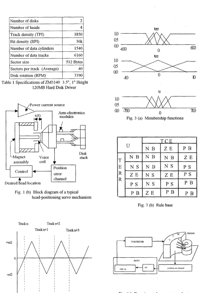
The experimental HDD, ZM3140 3.5", 1" height, 120 MB, is supported by the Zentek Storage
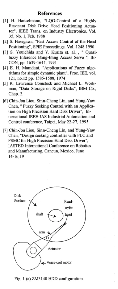
Inc., Shin-Chu, Taiwan with the specifications shown in Table 1. In this head-disk assembly (see Fig. 1 (a) and (b)), it is composed of the actuator, the amplifier, and the position error channel. The servo method is an embedded sector servo, in which the servo information is embedded in the data tracks as prerecorded sectors such that each head provide its own position information [ 5 ] . Fuzzy controller is 2472
constructed on a 80C196KB in circuit emulator
(ICE). ICE is a emulation device of 80196 single chip to help the development of controller during the design period. Finally, the fuzzy seeking con- troller of HDD can precisely drive the read-write
head servo mechanism to the desired track in the specified seek time without consuming too much control energy ,as demonstrated in experimental results.
2. System description 2.1 System specifications
The experimental HDD, ZM3140 3.5", 1" height 120 MB is supported by the Zentek Storage Inc., Shin-Chu, Taiwan with the specifications shown in table 2.1. In this head-disk assembly, it is embedded sector servo in which servo information is embedded in the data tracks as prerecorded sectors such that each head provide its own position in- formation. Moreover it has 2 number of disks , 4 number of heads and 1540 number of data cylinders
( see Fig. 1 (a) and (b)).
2.2 Head-Positioning Servomechanism
The head-positioning servomechanism in a hard disk provides a method for locating a set of read-write heads in fixed radial locations over the disk surface and allows the repositioning of these heads from one radial location to another. A block diagram of a typical head-positioning servo with a linear voice-coil motor type, with two arms, 4 heads , and four disks is shown on Fig. 1 (b) From the block diagram, we see that the whole controlled plant is composed of the actuator, the amplifier that drives current into the coil, and the position error channel.
The servo system has two primary functions :
one is to decide the position of the actuator and the other is to compare the difference of measured and
desired position and decide a optimal control to re- duce the error as soon as possible [5].
2.3 Position error signal
One of the significant parameters of HDD is the position error signal (PES) ,which is the out- put of the position error channel and proportional to the relative difference of the positions of the cen- ter of the servo head and the nearest track center. Hence the PES is period function of x (radial posi-
tion of the hcad) for stationary and ideal track cclx- ters ( see Fig. 2). The PES results from two sources of motion : motion of the actuator and motion of the disk surface itself. A simple mathematical descrip- tion of the PES is given by ( refers to [ 5 ] )
where w = track width
x = radial position of the head r = track center position reference
c = any constant such that
(r(9
-x(t)+
c) >0, for all r, x.
2.4 Actuator and Model
As shown in Fig 1 (b), actuator prime mov- er is voice-coil motor (VCM) consisting of a perma- nent magnet structure and a movable bobbin or coil attached through a T plate to the comb of arms car- rying the read-write heads. VCM have antecedents in the motors used in loudspeaker systems. A sim- ple linear model for VCM is a second order system likewise :where J is a gain constant through a system identification to identify its value. A proce- dure for identifying our HDD model is to use a white random signal through D/A converter into ac- tuator to move the read -write head reach the target
track and then reading the output of position error signal from A/D converter. A collection of input and output data pairs is used in analyzing frequen- cy responses of the systeni for identifying the gain
J. Notice that the gain J is slight varying for differ- ent target track. Although FLC is need no any pre- scribe system model
--
this is its main advantage, if we know a approximate rather than precise system model, it would greatly facilitate maters and look insight into the whole system under the development of FLC ,whereas this dependency of operator and expert knowledge is also its drawback.3. Fuzzy Seeking Controller
A PD-type FLC consists a set of rules, each rule can be symbolically described as follows:
i f e is <property symbol> and de is <prop-
erty symbol> then U is <property symbol>
where <property symbol> is the symbolic name of a linguistic value such as
i f e is positive big
PB)
and d e is positive big (PB) then U is negative big (NB)In Zentek HDD, the number of track in an indi- vidual disk surface is 1560 tracks. There are 256
units of division between two tracks. The read-write
head seeks in if control force in positive, md vice
versa. For the viewpoint of business, the 80C196KB
single chip is used as a computational center of the controller. A look-up table technique is adopted for the purpose of achieving the real-time inference. But, making a trade-off between the resolution of
the decision table and the size of the hardware memory is necessary for us. Therefore, a proper quantization of the universe of discourse is taken for the purpose of saving hardware memory and keep- ing the acceptable resolution. Three decision tables is constructed with hfferent input variables under distinct circumstance. The inputs of our fuzzy seek- ing controller are {terr, tce} or {err-n, ce-n} de- pends on which look-up table we used, they are defined as follows:
terr(track err.) = target track - current track
err-n(abso1ute position err.) = terr
*
256-
currentA
A
PES
A
tce(track change of err.) = current terr - previous terr
ce-n (absolute position change of err.) = tce*256
x (absolute position) = track number
*
256 + PES. Then three decision look-up tables is constructed as follows :1st Table:
A
Input variable 1 : terr,
U.D. = f600 tracks and Q.L. = 12 tracks Input variable 2: tce,
U D = + I 0 tracks and Q.L. = I track
2nd Table:
Input variable 1: terr,
U.D. =f12tracksandQ.L. =Itrack Input variable 2: ce-n,
U.D. = +256 units of division and Q.L. = 32 units of division 3rd Table:
Input variable 1: err-n,
U.D. = f256 units of division and Q.L. = 32 units of division
Input variable 2: ce-n,
U. D. = f 16 units of division and Q. L. = 1
unit of division
where U. D. means "universe of discourse" and Q. L. means "quantization level".
Notice that these look-up tables are actually gen- erated fiom the same rule base with properly select- ing the scaling factors to modify the universe of discourse. The membership functions of the term sets and the rule base are shown in Fig. 3 (a) and
Fig. 3 (b), respectively. The max-min inference en- gine and the center of gravity defuzzihcation meth- od are adopted in this work..
4.
System Setup
4.1 System Setup
The system setup is deplcted in Fig. 4. The hard disk drive was placed on the shock-resistant pad to avoid unusual vibration. And the connection of devices was through RS232 cable to construct a closed control loop. Furthermore, the controlled plant was a voice-coil motor (VCM) which was not only dnven by a VCM driver but also carry the read-write head servo mechanism for moving the read-write head to the desired target track as'soon as possible. The input of controller was a position error signal (PES) with 220 millisecond sampling time from the position error channel ,and the controller was then based on the PES to obtain the absolute position in the disk surface. The controller decided a control force to the VCM drive after comparison the Qscrepancy between the target track and a cur- rent track. The controller was constructed on 80C196KB in-circuit emulator (ICE) which is a de- vice of emulating a 80C196KB single chip to assist the development of controller during the design pe-
riod. The control programs was loaded into the Read Only Memory (ROM) rather than ICE when the controller design was accomplished; therefore, this control algorithm could implemented on commer- cial products.
4.2 Experimental Apparatus
The experimental apparatus was composed of the 80C196KB in circuit emulator, ZM3140 hard disk drive, power supply, 80486 personal computer, shock-resistant pad etc.. The related devices are ex- plained as follows:
A. The 80C196KB microcontroller
The MCS-96 family of 16-bit microcon- trollers consists of two sub-families: the 8096 and the 80C196 microcontrollers. A SOC196K.B micro-
controller was chosen as a center o f computations in t h s experiment.
B. The 80C196KB in circuit emulator
The 80C196KB In-Circuit Emulator (ICE) provided a means for developing, debugging and analyzing the software and hardware components of
the 80C196KE3 niicroprocessor or microcontroller based systems. The model USP-96 was a second generation of Signum's 80C196 emulators (see Fig. 4.2).The emulation POD-196 KBKC was plugged
into the target processor socket, and was connected to ICE via a ribbon cable.
C. Hard Disk Drive
The experimental HDD was the Zentek ZM3140, as explained in section 2 system descrip- tion.
D. Shock-resistant pad
The Shock-resistant pad was used to reduce possibly vibration by environment. This device was manufactured by Magfloat company in Japan with a total of 21Kg loaded capacity. But the HDD had only a weight of 0.5 Kg (1.1 Pounds), a iron of 1OKg is added on the pad to obtain a higher sensi- tivity of this shock-resistant pad.
E. The 80486 personal computer
The SO486 personal computer (PC) was ap- plied to development our fuzzy seeking control algo- rithms and executing ICE software so as to transfer the supremacy over the PC to the ICE.
5. Experimental Results
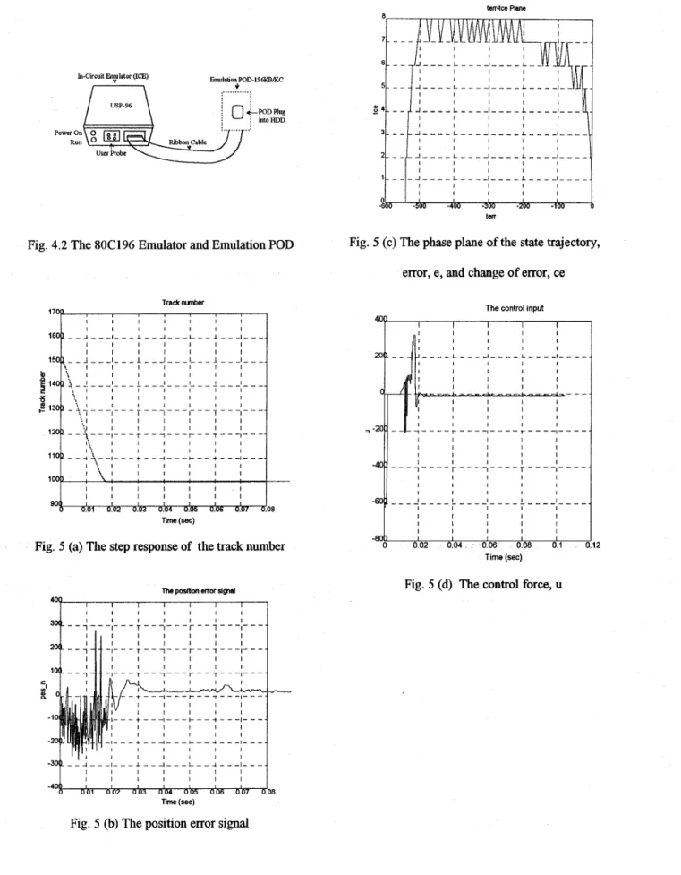
A read-write head moving from 1500th track to 1000th track is taken into account in this present study. A step response has no overshoot , as dem- onstrated in Fig. 5 (a). The position error signal
(PES), as observed from Fig. 5 (b), was getting to steady state in about 20 ms. A state trajectory asso- ciated error with change of error in phase plane, as was illustrated in Fig. 5 (c). A control force dnving the voice-coil motor was finally depicted in Fig. 5 (d). Some of advantages such as both the control effort in fuzzy logic seeking controller and the tem- perature on the HDD are less than those of the bang-bang control, as observed from a comparison with the bang- bang control [3]. This is one of rea-
sons that inhere in fuzzy logic seeking control -- it is robust with a rejection from temperature and oth- er disturbances.
6.
Conclusion
We have implemented a fuzzy seeking controller on a high precision hard disk driver. The proposed controller can successfully and precisely drive the read-write head servo mechanism to the desired target track within about 20 ms without con- suming too much control energy. To control a HDD by the fuzzy IF-THEN rules, it is not necessary to derive the mathematical model of HDD such that the controller should have the main advantages of the FLC, e.g.
,
insensitivity, robustness, low-cost ... etc. However, it also has the shortcomings of the FLC, e.g., there is no systematic way for stability analysis. One of the future research topics is fo-cused on how to applied the fuzzy sliding mode control approach we had developed on the HDD.
Refer en ces
[l] H. Hanselmann, "LQG-Control of a Highly Resonant Disk Drive Head Positioning Actua- tor", IEEE Trans. on Industry Electronics, Vol. 35, No. 1, Feb. 1988
[2] S. Hasegawa, "Fast Access Control of the Head
Positioning", SPIE Proceedings. Vol. 1248 1990 [3] S. Youichida and Y. Kurita et. al. , 'I Quasi-
fuzzy Inference Bang-Bang Access Servo
'',
IE-
[4] E. H. Mamdani, "Applications of Fuzzy algo- rithms for simple dynamic plant", Proc. LEE, vol. [ 5 ] R. Lawrence Conistock and Michael L. Work- man, "Data Storage on Rigid Disks", IBM Co., Chap. 2.
[6] Chin-Jou Liou, Sinn-Cheng Lin, and Yung-Yaw Chen, 'I Fuzzy Seeking Control with an Applica- tion on High Precision Hard Disk Driver", In- ternational BEE-IAS Industrial Automation and Control conference, Taipei, May 22-27, 1995 [7] Chin-Jou Liou, Sinn-Cheng Lin, and Yung-Yaw
Chen, "Design seeking controller with FLC and FSMC for High Precision Hard Disk Driver", IASTED International Conference on Robotics and Manufacturing, Cancun, Mexico, June
CON, pp. 1639-1644, 1991 121,110.12 pp. 1585-1588, 1974 14-16,19 \/ Actuator 4 Voicecoil motor
U
Fig. 1 (a) ZM3 140 HDD configuration
I
Number of disks 2 Number of headsTrack density (VI)
4 1850
I
Sectors per track (Average)I
40I
Bit density (BPI)Number of data cylinders
36k 1540
t\.
/Power current source Number of data tracksSector size
p
x
r
Armelectronics modulesl
1- 6160 512 Bytes Position Disk rotation (RPM)Fig. 1 (b) Block diagram of a typical head-positioning servo mechanism
3390 Trackn Tmcknt2 Tmckrtt-1 Tmcatn+3 I
1.0
05
tce
0.0
n W-10
U05
1
m
0.0
-m
0
Fig. 3 (a) Membership functions
Fig. 3 (b) Rule base
Fig. 4.1 Experimental apparatus and setup Fig. 2 A typical position error signal (PES)
terr-tce Plane
In-Circuit !2yIator (ICE)
/---I
Emulalion WD-196klM(C+
,... 0 I 1 400 -500 -400 I -300 I -200 I -100 I tenFig. 5 (c) The phase plane of the state trajectory, Fig. 4.2 The 80C196 Emulator and Emulation POD
error, e , and change of error, ce
Track mer
The control input
- 1 I I I I I I - 7 I I - f I - _ - - _
LL+
- --.K
I I I I I I I I I I I I I;
_ _ _ - ;
_ _ _ _ ;
_ _ - _ ;
_ _ _ _
I - - - - I I I - - _ _ _ _ I - - - 1_ _ _
I I I I I I I I I I I I 38 I I I I I I I I I I -80 I , I I I 0 002 004 006 0 0 8 0 1 Time (sec)Fig. 5 (a) The step response of the track number 12
Fig. 5 (d) The control force, U The position mor him1