224 I WM5-1
Actively Q-Switched All-Fiber Laser with a Fiber Bragg Grating of Variable
Reflectivity
Ding;-Wei Huang
Department of Electrical Engineering and Graduate Institute of Electro-Optical Engineering, National Taiwan University, Taipei, Taiwan, R.O.C.
Wein-Fung Liu
Department of Electrical Engineering, Chung Cheng Institute of Technology, Tahsi, Taoyuan, Taiwan, R.O.C.
Department of Electrical Engineering and Graduate Institute of Electro-Optical Engineering, National Taiwan University, 1, Roosevelt Road, Sec. 4, Taipei, Taiwan, R.O.C.
phone: 886-2-23657624 fax: 886-2-23652637 E-mail: ccy@cc.ee.ntu.edu.tw
c
a
Q-switching of erbium-doped fiber laser can provide simple and robust high-pulse-energy
light sources for various applications, including eye-safe rariging, remote sensing, medicine, and others. Typically, external-cavity acousto-olptical modulation was used for implementing Q- switching. However, the required external-c,avity configuration represents a drawback, which is open for improvement. It is expected that an all-fiber Q-switched laser can increase the efficiency and its robustness. In this paper, we report a novel Q-switched fiber laser based on an acoustically modulated fiber Bragg grating reflector. We used a fiber Bragg grating as the end mirror of the laser cavity. This fiber grating, was under acoustic perturbation for controlling its Bragg reflectivity. Therefore, the Q-factor of the laser cavity was switched high and low by the acoustic wave. Pulses of around 150 nsec in width and 7.6 pJ in pulse energy were obtained. The
laser slope efficiency was 13.1 %. This all-fiber Q-switched fiber laser can be quite compact and
robust.
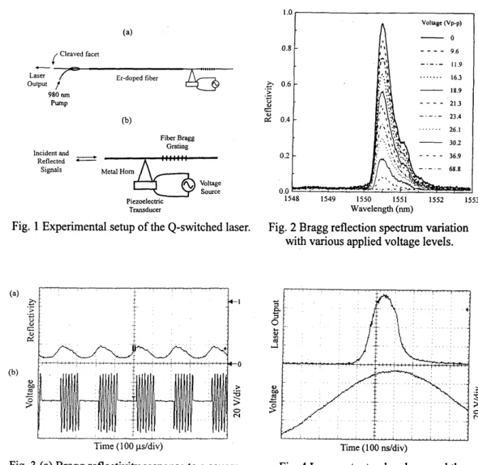
Figure 1 shows the experimental setup of the Q-switched fiber laser. Right to the 72-cm
long erbium-doped fiber, it was spliced to a fiber Bragg grating with the Bragg wavelength at
1550.5 nm. Between the grating and erbium-doped fiber, the fiber was laterally glued onto the tip
of a metal horn (made of aluminum), whose base was attached to a piezoelectric transducer (PZT), driven by a voltage source, for receiving mechanical vibration. This is the part of the setup for producing acoustic perturbation of the fiber grating. Left to the erbium-doped fiber, a WDM fiber coupler was connected for providing 980 nm pump power, which was provided by an argon-laser pumped Tisapphire laser. To the very left endl, the cleaved fiber facet was used as
the output coupler of the laser and provided about 4
YO
reflectivity. The whole cavity length wasWM5-2 I225
The fiber grating has a length of 1.5 cm and a Bragg reflection window of 0.5 nm, centered
at 1550.5 nm. The peak reflectivity was about 95 %. To concentrate the incoming acoustic power
the core of the fiber, the cladding of the fiber grating section was etched with HF solution to reduce the cladding diameter down to 30 pm. The length of this minimum cladding diameter was 2 cm with the 1.5-cm long grating located at the center. Including the two taper sections on both sides, the whole etched fiber length was about 5 cm. The metal horn was 1 cm in base diameter and 1.5 cm in length. Its tip was glued to the fiber about 2.5 cm from the grating center. Its base was glued to a thin PZT of 1.3 cm in diameter and 1.8 mm in thickness. The PZT was connected to a voltage source for driving acoustic waves. The acoustic waves propagated with increasing intensity along the horn to its tip and translated the power to the fiber. With the acoustic excitation, the fiber vibrated transversely to create micro-bending. The micro-bending produced the optical coupling between the core mode and cladding modes of the fiber. The cladding-mode power decayed through radiation. The out-coupling of optical core-mode signal reduced the power for Bragg reflection of the grating. Therefore, Bragg reflectivity of the fiber grating decreased with the intensity of the acoustic wave or the applied voltage to the PZT. Figure 2 shows the variation of Bragg reflection spectrum with various applied voltage levels when the acoustic frequency is 713 kHz. One can see that as the peak-to peak (p-p) voltage increases to 68.8 V, the Bragg reflectivity near 1550.5 nm is reduced to almost zero. This is the acoustic perturbation mechanism for Q-switching.
To see the response speed of the acoustic control of Bragg reflectivity, we applied a periodical square-wave modulation with various frequencies to the sinusoidal voltage signal at
713 kHz. Figure 3 shows the modulation response when the modulation frequency is 5 kHz. Part
(b) of this figure shows the applied sinusoidal voltage under 5
kHz
modulation with 50 % dutycycle. Part (a) shows the variation of Bragg reflectivity at 1550.5 nm of the fiber grating. One can see that switch-off of Bragg reflectivity is faster than switch-on as the acoustic wave is turned on and then off. The switching time depends on several parameters, including sound speed in fiber, the location of the horn tip along the fiber, the length of fiber grating, and the masses of the metal horn and PZT. The reflectivity starts to recover about 40 p e c after the voltage is turned off. Before turn-on of acoustic wave of the next cycle, only 60 psec left for reflectivity recovery. Because of the slow recovery and fast decay of Bragg reflectivity, the reflectivity value fluctuates between 0.06 and 0.27. Note that because the sampling rate of the used oscilloscope was not well set, the fast oscillation of the applied voltage in Fig. 3 does not represent the real acoustic frequency.
Figure 4 shows the laser output pulse profile and the applied voltage. Here, the Q-switching
frequency was 5 kHz, the applied voltage was 72 V (p-p), and the acoustic frequency was 713
226 I WM5-3
nsec. The laser threshold is near 2 mW and the slope efficiency is about 13.1 %. Take the case of 290 mW pump power as an example, it corresponds to the average output power of 38 mW or pulse energy of 7.6 pJ/pulse. With the pulse width of 150 nsec, the peak power is 50.7 W. It is believed that the pulse energy can be scaled up for at least several times.
f
facet-
Er-doped fiber Laser output I’ 980 nm P W P (b) Fiber Bragg Grating Metal Horn Source Incident and-
Reflected-
Signals Piezoelecbic TransducerFig. 1 Experimental setup of the Q-switched laser.
t
Time (1 00 pddiv)
Fig. 3 (a) Bragg reflectivity response to a sqmue- wave modulation of acoustic wave with modulation
-
18.9- 30.2
1548 1549 1550 1551 1552 1553
Wavelength (nm)
Fig. 2 Bragg reflection spectrum variation with various applied voltage levels.
Time (1 00 ns/div)
Fig. 4 Laser output pulse shape and the modulated applied voltage. fiequency at 5 kHz; (b) Variation of the app1ie:d voltage.