Experimental studies on optimal operating conditions for
different flow field designs of PEM fuel cells
Wei-Mon Yan
a,∗, Ching-Hung Yang
a, Chyi-Yeou Soong
b, Falin Chen
c, Sheng-Chin Mei
a aDepartment of Mechatronic Engineering, Huafan University, Shih-Ting, Taipei 223, TaiwanbDepartment of Aerospace and Systems Engineering, Feng Chia University Seatwen, Taichung 407, Taiwan cInstitute of Applied Mechanics, National Taiwan University, Taipei 106, Taiwan
Received 15 November 2005; received in revised form 30 December 2005; accepted 6 January 2006 Available online 17 February 2006
Abstract
In this work, the main focus is to measure the optimal cathode fuel flow rate effects with different flow field designs. In addition, the effects of different flow field designs (flow channel number, flow channel length, corner numbers and baffle effects) on the cell performance of the PEM fuel cells under the different operating conditions are examined. The experimental results reveal that the temperature effects generate the same trend in the five cathode flow field designs. When the cell temperature increases from 50 to 70◦C, the proton exchange membrane (PEM) experiences an insufficient hydration which causes an increase in ionic transport resistance. Therefore, the cell performance decreases with an increase in the cell temperature. In addition, increasing the cathode humidification improves the cell performance through enhancing the hydration level of the membrane and hence its ionic conductivity. For the effects of the cathode fuel flow rate on the cell performance, the PEM fuel cell with interdigitated flow field shows a better cell performance than that with the conventional flow field due to the baffle effect which forces the reactant gas through the gas diffuser layer. Furthermore, compared with conventional flow field, the PEM fuel cell with an interdigitated flow field can reach the same cell performance with a lower fuel consumption rate. Under the optimal fuel flow rate conditions, the PEM fuel cell with a parallel flow field with baffle provides the best cell performance among the five flow field designs.
© 2006 Elsevier B.V. All rights reserved.
Keywords: Fuel flow rate effect; Interdigitated flow field; Conventional flow field; Cell performance
1. Introduction
Recently, great attention has been drawn to the development of the proton exchange membrane fuel cell (PEMFC) among fuel cells due to its advantages over other fuel cells, such as, high energy density, no liquid corrosivity, operability at room temperature and a high-speed startup. Currently, researchers are focussed on low-humidity operations of PEMFCs, under which the high current density results in more water produc-tion, therefore a high water content and low ionic resistance of the membrane. Thus, integral numerical simulation analysis and experimental measurement are needed to find the optimal operating parameters and fuel cell design.
With the increase of operation time and current in PEMFC operation, water and thermal management become more and
∗Corresponding author. Tel.: +886 2 26632102; fax: +886 2 26632143.
E-mail address: [email protected] (W.-M. Yan).
more important. As for water management, this determines the cell performance during cell operation. Water flooding inside the cell would cause dehydration of the PEM and an increase of cell internal resistance, and consequently cell performance degrada-tion. In the case of water flooding inside the cell, the cathode gas diffuser layer would be blocked and the cathode gas would not be able to diffuse to the catalyst layer and take part in elec-trochemical reactions, causing degradation of the overall cell performance. Nguyen[1] analyzed the influences of different humidity conditions on the water and thermal management in a PEMFC. The results showed that hydration and ionic conduction are better in the portion of the membrane close to the fuel inlet, which increases the electro-osmosis coefficient and electricity carrying ability of the membrane, and the consumption rate of the anode hydrogen and the cathode oxygen. In the downstream flow field, less water is held by the membrane, and hydration and ionic conduction are weaker, which implies a lower fuel consumption and thereby lower cell performance. In addition, a high humidity temperature is required at high current density so 0378-7753/$ – see front matter © 2006 Elsevier B.V. All rights reserved.
Nomenclature
I current density (A cm−2) T temperature (◦C) V cell voltage (V) Subscripts
c condition at cathode side cell cell
in condition at cathode inlet
as to avoid PEM dehydration owing to insufficient water diffused to the anode from the cathode, and that appropriate operating parameters and effective removal of heat could improve the cell performance. Choi et al.[2] examined the water distribution in the membrane and discussed the effects of cathode humid-ity on it. The results showed that, as the cathode humidhumid-ity was exploited, the cathode absorption is predominant over electro-osmosis at low current density; in this case water contained in the membrane is mainly from the cathode. But with increasing current density and decreasing of the electro-osmosis resistance coefficient, the water supply on the anode side membrane is enhanced. Without cathode humidity, at low current density, the water in the membrane was mainly from the cathode side, and the water transport in the anode side is decreased owing to a large electro-osmosis resistance coefficient. But with increase in the current density, the cathode transport resistance is increased and the anode electro-osmosis resistance is decreased, making water carried by hydronium ions in transport a major source of water supply in the membrane. Djilali and Lu[3]investigated the effects of non-uniform temperature and pressure distribution on the cell performance and the water transport in the PEM fuel cell. The predicted results indicated that, with a small heat transfer coefficient, heat generated by the electrochemical reaction could not be removed effectively and the temperature distribution in the fuel cell might change greatly, causing a humidity deficiency in the membrane.
To resolve the problems of water management caused by elec-trochemical reaction in the PEM fuel cell, different designs in the PEMFC internal structure, graphite flow field plate or out-let exhaust system design have been tested in the past decade. Nguyen[4]and Wood et al.[5]investigated the effects of inter-digitated and conventional flow fields on the cell performance of PEM fuel cells. Experimental results showed that the cell perfor-mance with conventional flow field designs would descend with the progression of reaction and osmosis, due to water flooding caused by liquid water accumulation in the cathode side of the cell. For interdigitated flow field designs, water generated by electroreaction and osmosis could be effectively removed. At high current density, the PEM full cell with interdigitated flow field designs could retard the occurrence of the limiting current density and increase the PEM hydration and conductivity, with an efficiency enhancement by a factor of 30–100%. He et al.[6] and Yi and Nguyen[7]simulated the flow field in the cathode side of the PEM fuel cell with interdigitated flow field designs
and investigated the influences of electrode thickness of the cath-ode, flow channel number, shoulder width and pressure on the cell performance. Numerical results indicated that the current density increases with the increasing pressure, correspondingly a high stoichiometric oxygen flow rate is required. As the elec-trode thickness becomes larger, the gas transport path at the inlet gets too long, leading to a decrease in the current density at the inlet and the increase in the fuel supply flow rate. In addition, with an increase in the width ratio of the flow channel to shoul-der area, the gas through the shoulshoul-der area is raised due to a decrease in the cell internal resistance. Therefore, the increase of pressure difference and electrode thickness or reduction of the shoulder width could improve cell performance. Li et al.[8]and Um and Wang[9]analyzed the relation between the gas trans-port and the electrochemical reaction in the PEM fuel cell by a three-dimensional simulation. Predicted results showed that the gas fuel humidity has a significant impact on the output volt-age at high current density. While for the PEM fuel cell with an interdigitated flow field, the forced convection could enhance the efficiency of removing liquid water and the electrochemi-cal reaction, which in turn, result in a better cell performance. Nguyen and Knobbe[10]employed a new exhaust system to study the effects of the interdigitated flow field on the fuel con-sumption and the removal of liquid water. Experimental results showed that the continuous exhausting system could augment the efficiency of removing liquid water accumulated in the gas diffuser layer, which in turn, improved the cell performance. Yoon et al.[11]explored the current and temperature distribu-tions of the PEM fuel cell. From the results measured under the various humidity conditions, it was suggested that the flooding process begins at the gas outlet region of a cell, then it propagates to the inlet area. In addition, they concluded that the nitrogen atmosphere in air severely retards oxygen diffusion, especially in the lower stoichiometry condition.
Kazim et al. [12]numerically examined the differences in the limiting current density and the maximum power density between the conventional parallel flow field and the interdigi-tated flow field. Predicted results indicated that, despite a larger pressure loss in the interdigitated flow field, its limiting current density is three times as that in a conventional parallel flow field and the maximum power density is two times higher than that in a conventional parallel flow field, because of a higher efficiency of the electrochemical reaction due to the forced convection effects. Hontanon et al.[13]numerically investigated the influences of different permeabilities between the conventional flow channel and the porous material on the hydrogen consumption rate, pres-sure drop and cell performance. Numerical results showed that for the PEM fuel cell with a conventional flow field, the flow channel width and rib width variation would affect the hydro-gen consumption in the anode side. Dutta et al.[14]and Nguyen et al.[15]researched the gas transport inside the PEM fuel cell with a serpentine flow field. Predicted results indicated that the current density distribution would not be restricted under low load conditions due to oxygen diffusion, which result in a high current density near the collector electrode. As the load is being increased, the restriction effect on the oxygen transport near the collector electrode becomes more and more significant, leading
to a relative enhancement of oxygen concentration in the flow channel and a high current density in the flow channel. As for the temperature distribution, the predicted results showed that the temperature distribution is relatively homogeneous on the anode side, but the temperature distribution has a large gradient on the cathode side due to the electrochemical reaction in the catalyst layer. Dohle et al. [16]and Yan et al.[17]analyzed how the cell performance of the PEM fuel cell is influenced by the flow field designs. Predicted results indicated that as the flow channel length is increased, the fuel in the flow field would become insuf-ficient, and the effective working area is accordingly reduced, resulting in earlier occurrence of limiting current density. But when increasing flow channel width rather than flow channel number, the oxygen is distributed uniformly in the flow field, and the fuel consumption inside the cell is accordingly increased, promoting the electrochemical reaction and enhancing the cell performance. Additionally, increasing the porosity of the gas dif-fuser layer could augment the reactant gas through the catalyst layer. Kumar and Reddy[18]researched the influences of flow field sizes and shapes on the flow distribution and the cell perfor-mance of the PEM fuel cell. Numerical results showed that the pressure loss in the hemispherical flow field and the triangular flow field is much larger than that in the simple rectangular flow field. But the hydrogen consumption on the anode side is larger in the former two types of flow fields. Li et al.[19]discussed the influences of oxygen concentration on the cell performance of the PEM fuel cell by theoretical analysis and experimental mea-surement. Theoretical analysis indicated that in the downstream area, less oxygen concentration causes a lower gas transport rate and a decrease of current density. The difference between per-formance in the upstream area and the downstream area is over 10%. Experimental results showed that, at low current density, the natural convection and forced convection have similar influ-ences on the cell performance. But with the increasing current density, the forced convection remains a high output voltage, while for natural convection the cell performance is remarkably degraded. Argyropouos et al. [20,21]studied numerically the influences of the optimal operating parameters on the pressure loss in a triangular flow field. They indicated in the simulation results that, on the cathode and anode side of the DMFC, the inlet temperature, temperature gradient or methanol concentra-tion have no evident influence on pressure loss in the flow field designs. Arico et al.[22]examined the influence of a serpen-tine flow field design and interdigitated flow field design on the gas transport and cell performance of the DMFC. Experimental results showed that at a low current density, the DMFC with a serpentine flow field gets a lower pressure loss in the active area and less methanol fuel crossover, and thereby obtains a high fuel efficiency and open circuit voltage. In the DMFC with interdigi-tated flow field, the forced convection mechanism could augment the gas transport in high current density area and reduce the pres-sure loss in the gas diffuser layer. Pasaogullar and Wang[23] mainly investigated the electrochemical change, current distri-bution, reactant flow field distribution and gas fuel transport in three-dimension area in different cell shapes and operating con-ditions. Predicted results showed that, at the bottom of gas flow field and current collector plate, the electrochemical reaction is
blocked, leading to a low current density distribution in this area. As for an interdigitated flow field, the forced convection could increase the reactant gas through the porous gas diffuser layer to the catalyst layer, releasing the restriction on the gas transport in this area. Meanwhile, it could effectively enhance the cathode liquid water removal efficiency, and consequently enhance the overall cell performance by a factor of 30%.
It was found from the above literature survey that the previ-ous studies associated with the flow field designs mainly focused on numerical simulation, which discussed the influences of a single flow field on the cell performance, including flow chan-nel width and length, electrode thickness and rib width. Yet, the experimental studies on the cell performance of the PEM fuel cells with different flow field designs are few. This moti-vates the present study. In this work, the cell performance of PEM fuel cells with different flow field design was examined experimentally. In addition, the optimal operating conditions for the PEM fuel cells with different flow field designs is presented.
2. Principles of flow field designs
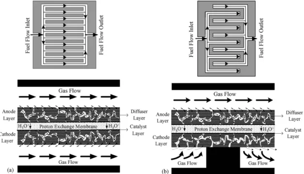
In the present study, PEM fuel cells with five flow field designs are investigated experimentally in detail. For the conve-nience of the discussion, the five flow fields could be divided into two types, that is, conventional flow field designs and interdigi-tated flow field designs. Conventional flow field designs mainly included a parallel flow field design, Z-type flow field design and serpentine flow field design. Study on these three designs with different flow channel numbers and flow channel lengths provides a better understanding of the differences in fuel con-sumption inside the flow field and the fuel cell internal loss. Furthermore, the shearing stress effect generated in corners of Z-type flow field helps to enhance the liquid water removal effi-ciency and fuel effieffi-ciency in these areas. Interdigitated flow field designs mainly include parallel flow field with baffle and Z-type flow field with baffle. Different from conventional flow field designs, interdigitated flow field designs have baffles in the flow field that could intensify forced convection of gas transport (shown inFig. 1) and force reactant gas to flow into the fuel cell, which in turn, would promote the electrochemical reaction and the cell performance. For comparison purposes, the five flow field designs have the same flow channel width, flow channel depth and rib width. The differences between these designs lie in the flow channel number, flow channel length, number of corners and the baffle effect. Flow channel numbers and sizes of five flow field designs are shown inTable 1. The main pur-poses are to discuss how the cell performance of the PEM fuel cells with different flow fields is influenced by the flow rate, cell temperature and humidification temperature.
3. Experiment setup and methodology
3.1. Materials and sizes of the fuel cells
The PEMFC usually has seven layer structures, that is, an anode flow field, an anode gas diffuser layer, an anode catalyst
Fig. 1. The physical schematic diagrams of the fuel flow within the PEM fuel cell with different flow fields: (a) conventional flow field and (b) interdigitated flow field.
layer, a proton exchange membrane, a cathode catalyst layer, a cathode gas diffuser layer and a cathode flow field. The material of the end plate used in this work was aluminum alloy 7075 with a cross section of 26 cm× 26 cm and a width of 2 cm. The collector plate was made of highly conductive copper and gold-plated on the surface to increase its surface conductivity and reduce contact resistance to bipolar plate. The collector plate had a size of 22 cm× 22 cm and width of 0.4 cm. The material for the air-tight seal was Teflon, and its size was 14 cm× 14 cm. The air-tight seal is used to reinforce air tightness for the gas fuel transport inside the cell to avoid energy loss and air leakage. The bipolar plate in experiments is a pure graphite plate, which has a size of 22 cm× 22 cm, a depth of 0.3 cm and a surface size of 13.7 cm× 13.7 cm for flow field machining. The bipolar plate is used to fabricate the flow field on its surface, which provides paths for the anode and cathode gases to the MEA. The MEA used was a three-layer combination of PEM and catalyst layers. The thickness of the PEM was 35m. The catalyst layer has a discrepancy in the two side thicknesses due to different content and composition of the Pt alloy between the anode and the cathode. The size of the catalyst layer is 14.1 cm× 14.1 cm, that is, a reactive area of 198.1 cm2, which has a direct influence
on the fuel cell power produced by the electrochemical reaction. The material of the gas diffuser layer was carbon paper, which had a size of 14 cm× 14 cm and a thickness of 0.04 cm. 3.2. Experiment setup
The schematic view of the experiment test system is shown inFig. 2. The test bench included five parts: gas supply system, flow rate control system, temperature control system, humid-ity system and electric load system. The gas supply system supplied hydrogen, oxygen and air as the anode and cathode reactant gas to the fuel cell, and supplied nitrogen for removing the residual gas in the pipeline before and after the experiments. The flow rate control system controled the gas inlet flow rate following stoichiometry and minimum flow mode. In the tem-perature control system, a heating rod, T-type thermocouple and CN760000 temperature controller were employed to con-trol the cell temperature. The humidity system forced the gases through humidification bottles and regulated the temperature of the humidified fuel gases. The electric load system had the max-imum power output of 600 W, a maxmax-imum current of 120 A and the maximum voltage of 60 V.
Table 1
The specifications of the tested flow field designs in this work
Parallel flow field Parallel flow field with baffle
Serpentine flow field Z-type flow field Z-type flow field with baffle
No. of flow channels 69 69 23 34 34
Channel width (cm) 0.1 0.1 0.1 0.1 0.1
Channel length (cm) 14.1 14.1 41.3 20.6 20.6
Channel depth (cm) 0.1 0.1 0.1 0.1 0.1
Fig. 2. Schematic diagram of the experimental setup.
4. Results and discussion
Fig. 3illuminates the cathode gas fuel flow rate on the cell per-formance of PEM fuel cells with conventional flow field designs by using oxygen and air. It is clearly observed that when oxygen is supplied as the cathode fuel, the oxygen flow rates for the parallel flow field, Z-type flow field and serpentine flow field are 1000, 3000 and 2000 cm3min−1, respectively, which are sufficient to react with hydrogen at the anode. This is due to the differences in the flow channel number, flow channel length and corner effects among these three conventional flow field designs that introduce the discrepancy in the fuel flow rate inside the flow channel field and the oxygen reaction consumption in the catalyst layer. Thus, although Z-type flow field has oxygen fuel consumption as high as 3000 cm3min−1, the corner effect
increases the electrochemical reaction in the catalyst, making its cell performance better than that of the parallel flow field. For the operating condition of a lower current density, the Z-type flow field can provide a larger fuel reactive area than the serpentine flow field. Therefore, a Z-type flow field design has a higher oxy-gen consumption. But, considering the fuel cell performance, the cell performance of the PEM fuel cell with a Z-type flow field is better than that of a parallel flow field or a serpentine flow field. For the air as reactant, the cell performance of a serpentine flow field is better than that of a parallel flow field or a Z-type flow field under the lower air flow rate condition. This can be made plausible by noting the fact that with the addition of the corner effect in the serpentine flow field, the fuel flow rate in the catalyst layer is raised, which in turn, retards the occurrence of limiting current density at a low air flow rate.
Fig. 3. Effects of the flow rate on the cell performance of PEM fuel cells with different flow field designs: (a) oxygen and (b) air.
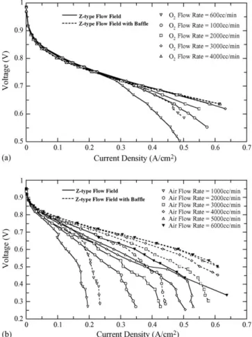
The effects of oxygen and air flow rates on the cell perfor-mance are shown inFig. 4for a Z-type flow field with or without a baffle. It is clearly observed in Fig. 4(a) that when oxygen is supplied as the cathode gas, the required oxygen flow rate for a Z-type flow field with baffle was 2000 cm3min−1, which was sufficient for reacting the anode hydrogen. While for a Z-type flow field without a baffle, a minimum oxygen flow rate of 3000 cm3min−1was required. Such a difference in the required oxygen flow rates is caused by the discrepancy in reactant oxy-gen quantity in the catalyst layer in the two designs due to the baffle effect. For a Z-type flow field with baffle, the forced con-vection caused by baffle enhances the gas fuel through the gas diffuser layer, thus, less oxygen was needed than that in a Z-type flow field design. It was concluded fromFig. 4(b) that when air is employed as the cathode gas, the air flow rate of a Z-type flow field with baffle was 5000 cm3min−1, which provides a better overall cell performance than Z-type flow field with air flow rate of 6000 cm3min−1. As air was the gas, besides 1/5 proportion of oxygen contained in the air, there was still a 4/5 proportion of nitrogen and other gases. As a result, the nitrogen and other gases tend to be absorbed in the catalyst layer surface at high current density, causing cell performance degradation. While in a Z-type flow field with baffle, the baffle effect brought an increase of the gas flow rate through the diffuser layer, which helps to remove nitrogen and other gases absorbed in the catalyst layer, and con-sequently improves cell performance and retards the occurrence
Fig. 4. Effects of the flow rate on the cell performance of PEM fuel cells with Z-flow fields with or without baffles: (a) oxygen and (b) air.
of limiting current density. In addition,Fig. 4(b) shows that, at a voltage of 0.6 V and an air flow rate of 6000 cm3min−1, the current density is 0.34 and 0.48 A cm−2, respectively, enhanced by a factor of 1.41 times in the Z-type flow field design with baffle.
The effects of fuel flow rates on the cell performance of the PEM fuel cell with a parallel flow field with or without baffle are presented inFig. 5.Fig. 5(a) indicates that, when oxygen is supplied as the cathode gas, the required oxygen flow rate in a parallel flow field with baffle is 2000 cm3min−1, which is suf-ficient for reacting with hydronium ions from the anode. While in a parallel flow field without baffle, a minimum oxygen flow rate of 3000 cm3min−1is required. In a parallel flow field with baffle, there is an increase in oxygen gas through the gas diffuser layer to the catalyst layer due to the forced convection caused by the baffle effect, which implies an increase of effective reactive area. Therefore, baffles in parallel flow field could enhance the cell performance and reduce the oxygen consumption.Fig. 5(b) shows, at the cathode air flow rate of 1000 cm3min−1, the cell performance with a parallel flow field with baffle is much higher than that with parallel flow field without baffle. As the cathode air flow rate is increased, the cell performance of the two designs are both enhanced, and parallel flow field with baffle still remains at high efficiency. The reason is due to the fact that there is an increase in oxygen gas through the gas diffuser layer to the cat-alyst layer due to the forced convection generated by the baffle
Fig. 5. Effects of the flow rate on the cell performance of PEM fuel cells with parallel flow fields with or without baffles: (a) oxygen and (b) air.
effect. Additionally, the forced convection enhances the reactant fuel flow rate to remove nitrogen and other gases absorbed to the catalyst layer, and at voltage of 0.6 V and air flow rate of 6000 cm3min−1, the current density is 0.44 and 0.53 A cm−2, respectively, enhanced by a factor of 1.2 times in a parallel flow field with baffle. It is worth noting that the above conclusion is only applied to the present conditions. For low humidification operations, which are much more popular currently, a high gas flow rate may dry out the membrane and consequently decrease the cell performance[11]. It could be concluded from the mea-sured results, as air is the cathode inlet gas, the baffle effect could retard the incidence of a limiting current density and enhance the overall cell performance effectively.
For a better understanding of the influences of different inter-digitated flow field designs on the cathode inlet fuel flow rate and the cell performance, the effects of fuel flow rates on the cell per-formance for parallel flow field with baffle and Z-type flow field with baffle are explored inFig. 6. As shown inFig. 6(a), when pure oxygen is supplied as the cathode fuel, the required oxy-gen flow rate in parallel flow field with baffle is 600 cm3min−1, which is sufficient for reacting with hydronium ions from the anode. While in a Z-type flow field with baffle, a minimum oxy-gen flow rate of 2000 cm3min−1is required. Such a contrast is due to the differences in flow channel number and flow channel length. At a cathode oxygen flow rate of 600 cm3min−1, the
Fig. 6. Effects of the flow rate on the cell performance of PEM fuel cells with parallel flow fields with baffle and Z-flow field with baffle: (a) oxygen and (b) air.
flow channel length in Z-type flow field is too long, resulting in an insufficiency of oxygen fuel at the end of the flow field and a reduction of reactive area, thus leading to the incidence of lim-iting current density. In a parallel flow field with baffle, the flow channel length is about 2/3 of that in a Z-type flow field with baffle, ensuring that oxygen from the cathode is able to diffuse to the catalyst layer and take part in electrochemical reactions. Although the flow channel number within the bipolar plate is twice that in a Z-type flow field with baffle. Thus, in these two types of interdigitated flow field designs, the parallel flow field with baffle could reduce the cathode oxygen consumption effec-tively.Fig. 6(b) indicates that, at low air flow rates, insufficiency of oxygen contained in the air causes an earlier incidence of limiting current density in both interdigitated flow field designs. But with the increase in the air flow rate, the reactant oxygen in the catalyst layer is increased. Thus, the overall cell performance is improved. In addition, it is found out that at an air flow rate of 5000 cm3min−1, the overall cell performance is better than that of a Z-type flow field with baffle. This is because it has a larger number of flow channels, which slows the air flow rate in the flow channel. Therefore, the oxygen could completely react with the anode hydrogen at a high air fuel flow rate. Contrari-wise, the flow channel number in Z-type flow field with baffle is half the number in a parallel flow field with baffle, and the air fuel obtains a high flow speed in the flow channel. As a result,
the oxygen in the air could not react completely, leading to lower cell performance than parallel flow field with baffle. Therefore, when air is the cathode gas, a parallel flow field with baffle could effectively make use of oxygen contained in the air.
The influences of the optimal gas fuel consumption on the cell performance of the PEM fuel cells with five flow field designs under the optimal operating conditions are shown inFig. 7. It is apparent inFig. 7(a) that there are differences between the five cathode flow field designs in flow rate inside the flow field and gas diffusion mode, which brought a discrepancy in the optimal oxygen flow rate supply. As the oxygen is the gas in a parallel flow field with baffle and a Z-type flow field with baffle, there is an increase in oxygen gas through the gas diffuser layer to the catalyst layer due to the forced convection generated by the baffle effect, and accordingly an increase of the effective reactive area, which could enhance the cell performance and reduce oxygen consumption. As a whole, in the five cathode flow field designs, the parallel flow field design is able to enhance the fuel cell performance and evidently reduce fuel consumption compared with the other four designs, that is, an optimal oxygen flow rate supplied by the cathode as low as 600 cm3min−1. As air is the fuel gas in the parallel flow field with baffle, there is an increase of oxygen gas through the gas diffuser layer to the catalyst layer due to the forced convection generated by the baffle effect. Furthermore, at a higher air flow rate, because of a larger
Fig. 7. The cell performance of the PEM fuel cells with different flow fields under optimal operating conditions: (a) oxygen and (b) air.
Table 2
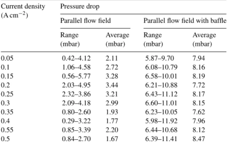
The measured pressure drops for the PEM fuel cells with an interdigtated flow field and conventional flow field for an oxygen flow rate of 1000 cm3min−1 Current density
(A cm−2)
Pressure drop
Parallel flow field Parallel flow field with baffle Range (mbar) Average (mbar) Range (mbar) Average (mbar) 0.05 0.42–4.12 2.11 5.87–9.70 7.94 0.1 1.06–4.58 2.72 6.08–10.79 8.16 0.15 0.56–5.77 3.28 6.58–10.01 8.19 0.2 2.03–4.95 3.44 6.21–10.88 7.72 0.25 2.32–3.86 3.21 6.43–11.12 8.17 0.3 2.09–4.18 2.99 6.60–11.01 8.15 0.35 0.80–2.60 1.93 6.23–10.05 7.62 0.4 0.29–3.22 1.77 5.98–11.92 7.96 0.55 0.85–3.39 2.20 6.44–10.68 8.12 0.5 0.84–2.70 1.67 6.39–11.41 8.47
flow channel number in the bipolar plate, the air fuel inside flow field is slowed down and thus could completely react in the electrochemical reactions and improve the I–V performance curve. Contrariwise, at a high air flow rates, by reason that the Z-type flow field had half the flow channel number as the f parallel design, the flow rate in the flow field is increased and oxygen in the air cannot be completely used, leading to a lower cell performance than the other four cathode flow field designs.
Additionally, in conventional parallel flow field and interdigi-tated parallel flow fields with baffle, pressure drops are measured experimentally and shown inTable 2. It is shown inTable 2that at the same oxygen flow rate, the average pressure drops for all tested cases in a parallel flow field without and with baffle are about 2.53 and 8.05 mbar, respectively, increased by a factor 3.2 times. Whereas the actual inlet pressure required in the cathode is increased by 0.00552 atm. As for the fuel cell performance, it is improved by a factor of 5.32% in parallel flow field with baffle at voltage of 0.7 V.
5. Conclusion
In this work, the main focus was to find the optimal operating conditions, including humidification temperature, cell temper-ature and cathode inlet gas flow rate, for the PEM fuel cells with different flow fields and examine the effects of the differ-ent flow fields (flow channel number, flow channel length, corner numbers and baffle effects) on the cell performance under dif-ferent operating conditions. Comparison among the PEM fuel cells with conventional flow field designs reveals that, with an increase in the flow channel number, the flow channel length and the corner number in a serpentine flow field, the electrochemical reaction is raised. Thus, it is beneficial to complete the use of the supplied fuel and enhancement of the cell performance as air is the cathode gas. The PEM fuel cell with a parallel flow field has three times more channels than the serpentine flow field, thus it provides a better ability of gas diffusion in the flow field at the condition of low current density. While at the operating condition of high current density, the corner areas inside the ser-pentine flow field augments the mass transport of the reactant gas
and thereby enhances the overall cell performance. Therefore, in conventional flow field designs, appropriate flow channel num-bers, flow channel lengths and corner numbers could effectively improve the cell performance. As for the optimal parameters, the PEM fuel cell with a parallel flow field with a baffle shows a better cell performance due to the baffle effect which forces the reactant gas through the gas diffuser layer under optimal operating conditions, and less reactant gas is required than in conventional flow field designs. However, a larger number of flow channels implies a slower fuel transport rate inside the flow field and a more complete reaction. So in interdigitated flow field designs, the PEM fuel cell with a parallel flow field with baffle can provide a better furl cell performance than that with a Z-type flow field with baffle. The effect of liquid water on the fuel cell operation between the different flow field designs is also important and will be investigated in the near future.
Acknowledgement
The study was supported by the National Science Council, the Republic of China, through the grants NSC 93-2212-E-211-011, NSC 2623-7-002-006-ET, 2212-E-035-027 and NSC 92-2212-E-002-096.
References
[1] T.V. Nguyen, R.E. White, A water and heat management model for proton-exchange-membrane fuel cells, J. Electrochem. Soc. 140 (1993) 2178–2186.
[2] H.K. Choi, H.D. Peck, S.C. Kim, R.D. Shin, Water transport in polymer membranes for PEMFC, J. Power Sources 86 (2000) 197–201.
[3] N. Djilali, D. Lu, Influence of heat transfer on gas and water transport in fuel cells, Int. J. Therm. Sci. 41 (2002) 29–40.
[4] T.V. Nguyen, A gas distributor design for proton-exchange-membrane fuel cells, J. Electrochem. Soc. 143 (1996) L103–L105.
[5] D.L. Wood, J.S. Yi, T.V. Nguyen, Effect of direct liquid water injection and interdigitated flow field on the performance of proton exchange fuel cells, Electrochm. Acta 43 (1998) 3795–3809.
[6] W. He, J.S. Yi, T.V. Nguyen, Two-phase flow model of the cathode of PEM fuel cells using interdigitated flow fields, AIChE J. 46 (2000) 2053–2064. [7] J.S. Yi, T.V. Nguyen, Multicomponent transport in porous electrodes of proton exchange membrane fuel cell using the interdigitated gas distributor, J. Electrochem. Soc. 146 (1999) 38–45.
[8] P.W. Li, L. Schaefer, Q.M. Wang, T. Zhang, M.K. Chyu, Multi-gas trans-portation electrochemical performance of a polymer electrolyte fuel cell with complex flow channels, J. Power Sources 115 (2003) 90–100. [9] S. Um, C.Y. Wang, Three dimensional analysis of transport and reaction in
proton exchange membrane fuel cells, in: Proceedings of the ASME Fuel Cell Division, 2000.
[10] T.V. Nguyen, M.W. Knobbe, A liquid water management strategy for PEM fuel cell stacks, J. Power Sources 114 (2003) 70–79.
[11] Y.G. Yoon, W.Y. Lee, T.H. Yang, G.G. Park, C.S. Kim, Current distri-bution in a single cell of PEMFC, J. Power Sources 118 (2003) 193– 199.
[12] A. Kazim, H.T. Liu, P. Forges, Modelling of performance of PEM fuel cells with conventional and interdigitated flow fields, J. Appl. Electrochem. 29 (1999) 1409–1416.
[13] E. Hontanon, M.J. Escudero, C. Bautista, P.L. Garcia-Ybarra, L. Daza, Optimisation of flow-field in polymer electrolyte membrane fuel cells using computational fluid dynamics techniques, J. Power Sources 86 (2000) 363–368.
[14] S. Dutta, S. Shimpalee, J.W. Van Zee, Numerical prediction of mass-exchange between cathode and anode channels in a PEM fuel cell, Int. J. Heat Mass Transfer 44 (2001) 2029–2042.
[15] P.T. Nguyen, T. Berning, N. Djilali, Computational model of a PEM fuel cell with serpentine gas flow channels, J. Power Sources 130 (2004) 149–157. [16] H. Dohle, A.A. Kornyshev, A.A. Kulikovsky, J. Mergel, D. Stolten, The current voltage plot of PEM fuel cell with long feed channels, Electrochem. Commun. 3 (2001) 73–80.
[17] W.M. Yan, C.Y. Soong, F. Chen, H.S. Chu, Effects of flow distributor geom-etry and diffusion layer porosity on reactant gas transport and performance of proton exchange membrane fuel cells, J. Power Sources 125 (2004) 27–39.
[18] A. Kumar, R.G. Reddy, Effect of channel dimensions and shape in the flow-field distributor on the performance of polymer electrolyte membrane fuel cells, J. Power Sources 113 (2003) 11–18.
[19] P.W. Li, T. Zhang, Q.M. Wang, L. Schaefer, M.K. Chyu, The performance of PEM fuel cells fed with oxygen through the free-convection mode, J. Power Sources 114 (2003) 63–69.
[20] P. Argyropoulos, K. Scott, W.M. Taama, Pressure drop modeling for liquid feed direct methanol fuel cells. Part I. Model development, Chem. Eng. J. 73 (1999) 217–227.
[21] P. Argyropoulos, K. Scott, W.M. Taama, Pressure drop modeling for liquid feed direct methanol fuel cells. Part II. Model based parametric analysis, Chem. Eng. J. 73 (1999) 229–245.
[22] A.S. Arico, P. Creti, V. Baglio, E. Modica, V. Antonucci, Influence of flow field design on the performance of a direct methanol fuel cell, J. Power Sources 91 (2000) 202–209.
[23] U. Pasaogullar, C.Y. Wang, Computational fluid dynamics modeling of proton exchange membrane fuel cells using fluent, Electrochemical Engine Center, The Pennsylvania State University.