Face Tracking Interaction Control of a
Nonholonomic Mobile Robot
Chi-Yi Tsai and Kai-Tai Song
Department of Electrical and Control Engineering National Chiao Tung University
1001 Ta Hsueh Road, Hsinchu, 300 Taiwan, ROC [email protected]; [email protected] Abstract - This paper presents a novel face tracking control
scheme for human-robot interaction control in image plane. This control scheme is robust to the velocity quantization error in practical implementation. A visual tracking controller is designed for ensuring global asymptotic stability of the closed-loop visual tracking system based on an error-state control model in image plane. In order to overcome the quantization uncertainty encountered in practical systems, an image-based robust control law is proposed to guarantee the stability of the robotic control system based on Lyapunov theory. This design provides a useful solution for smooth visual tracking control of slow-motion robots in a home setting.Simulation and Experimental results verify the effectiveness of the proposed visual tracking control scheme, both in terms of tracking performance and system convergence.
Index Terms – human-robot interaction; visual tracking control; interaction control; real-time face tracking.
I. INTRODUCTION
One important function of intelligent service robots, such as exhibition guide robots or health-care robots, is how it can interact with people. In other words, the way robots interact with human beings will be an essential factor for practical applications of home/service robotics. Due to the advantages of computer vision, cameras have become one of the most popular perception sensors employed for autonomous robots. The research on vision-based human-robot interaction has been an active area of robotic research in recent years [1]-[4]. The purpose of this study is to develop a face tracking interaction control system for a nonholonomic mobile robot with velocity quantization uncertainty in applications in home service scenarios.
Vision-based human-robot interaction has been studied for visual tracking of moving people [1] or objects [2]. Reported visual tracking methods usually focus on the discussion of image processing issues such as object detection, recognition and tracking in image plane. In [1], Zajdel et al. proposed a mixed visual tracking algorithm which combines various visual cues and the motion data of mobile robot to achieve object detection, local tracking and visual identification of people. In [2], Mojaev and Zell proposed a real-time object tracking algorithm which applies a well-known discriminator technique to estimate the scale factor and roll angle of the tracked object related to a template image. Only a few reported methods focus their discussions on the issues of combining face tracking algorithm with the control of nonholonomic
mobile robots. Feyrer et al. proposed a controller to control a wheeled mobile robot with a pan-tilt camera platform to track and pursuit a detected person [3]. In [4], Song et al. combined a real-time image processing system with a PID controller for a wheeled mobile robot to achieve human’s face detection, recognition and tracking control. In many practical applications such as health-care service robots, it is important for a mobile robot to focus its attention on the user effectively and interactively. This problem motivates us to investigate the control issues of face tracking interaction for improving the tracking performance of wheeled mobile robots for human-robot interaction.
In this paper, the preliminary derivation of the control scheme proposed in [5] is extended to face tracking interaction control design. To do so, a generalized image-based error-state control model is derived first for face tracking controller design. Moreover, in order to overcome the velocity quantization error encountered in practical systems, a robust control law based on Lyapunov theory is then proposed for ensuring global asymptotic stability of the practical closed-loop visual tracking system. Simulation and experimental results are presented to show the effectiveness of the proposed face tracking control scheme, both in terms of tracking performance and system convergence.
II. SYSTEMMODEL IN IMAGEPLANE
In this study, the design of vision-based human-robot interaction control is considered as a face tracking interaction control problem such that a mobile robot with a tilt camera mounted on top of it can track the user’s face in image plane. Figs. 1 (a) and (b) show the scenario under consideration. A tilt camera is mounted on the unicycle-modeled mobile robot and its optical-axis faces to the user’s face. The kinematics of the nonholonomic mobile robot and the user can be described, respectively, by m f m f m f m f m f m f m f m f w v x v z = = = θ θ θ & & & sin cos ,
φ
&
=
w
tf and y f h f x f h f z f h f v y v x v z = = = & & & (1) where ( , m) f m f x z and ( , , h) f h f h f x yz are, respectively, the positions of the mobile robot and the user’s head in world coordinates.
) , (θm φ
f are the orientation angle of the mobile robot and the tilt
Proceedings of the 2006 IEEE/RSJ
International Conference on Intelligent Robots and Systems October 9 - 15, 2006, Beijing, China
angle of the mounted camera. ( , m) f m f w
v are the linear and angular velocity of the mobile robot; t
f
w is the tilt velocity of the camera. (vzf,vxf,vyf)are the head velocity of the user in world coordinates. The authors’ previous work in [5] is adopted to derive the system model in camera frame and the results are shown below.
h m f c c c c A X Bu R V X& = + + (
φ
,θ
) , (2) where ⎥ ⎥ ⎥ ⎦ ⎤ ⎢ ⎢ ⎢ ⎣ ⎡ − − − = 0 cos 0 sin cos sin 0 t f m f t f m f m f m f c w w w w w w A φ φ φ φ , ⎥ ⎥ ⎥ ⎦ ⎤ ⎢ ⎢ ⎢ ⎣ ⎡ − ⎥ ⎥ ⎥ ⎦ ⎤ ⎢ ⎢ ⎢ ⎣ ⎡ − − − = ⎥ ⎥ ⎥ ⎦ ⎤ ⎢ ⎢ ⎢ ⎣ ⎡ = 0 0 ) , ( y z z y y x x R z y x X m f h f m f h f m f h f m f c c c c φθ δ , ⎥ ⎥ ⎥ ⎦ ⎤ ⎢ ⎢ ⎢ ⎣ ⎡ − = y y Bc δ φ φ φ δ 0 cos 0 0 sin 0 sin 0 , ⎥ ⎥ ⎥ ⎦ ⎤ ⎢ ⎢ ⎢ ⎣ ⎡ = t f m f m f w w v u , ⎥ ⎥ ⎥ ⎦ ⎤ ⎢ ⎢ ⎢ ⎣ ⎡ − − − = m f m f m f m f m f m f m f R θ φ φ θ φ θ φ φ θ φ θ θ θ φ cos cos sin sin cos cos sin cos sin sin sin 0 cos ) , ( , ⎥ ⎥ ⎥ ⎦ ⎤ ⎢ ⎢ ⎢ ⎣ ⎡ = z f y f x f h v v v V ,y
δ
is the distance between the head of the robot and the mounted camera. Next, we need to define the system states in image frame for the controller design. Fig. 2 illustrates the definition of observed system states associated with human face in image plane. By the definition of the diffeomorphism:[
]
[
]
T x c y c x T x i i i x y d k x k y k F X = = − , k =x fx zc , c y y f zk = where xi and yi are, respectively, the horizontal and vertical position of the centroid of human face in image plane. d is the width of human face in image plane. x (fx,fy) represent the fixed focal length along the image x-axis and y-axis, respectively [6]. F denotes the width of the human face. The kinematic interaction between robot and human face in image frame can be obtained by taking the derivative
Fig. 2. The definition of observed system states associated with a human face in image plane.
of the expression in diffeomorphism. The result is shown below. i i i i i AX Bu C X& = + + , (3) where ) , , (A1 A2 A1 diag Ai= , ) cos cos sin sin cos ( 1 hx mf hy hz fm x x v v v f k A =− φ θ + φ+ φ θ , ) cos cos sin sin cos ( 2 hx fm hy hz mf y y v v v f k A =− φ θ + φ+ φ θ , ⎥ ⎥ ⎥ ⎥ ⎥ ⎥ ⎥ ⎥ ⎦ ⎤ ⎢ ⎢ ⎢ ⎢ ⎢ ⎢ ⎢ ⎢ ⎣ ⎡ + − + + − + + + − + − + = ) ( 1 cos cos ) ( ) cos (sin ) cos (sin ) ( 1 sin ) ( cos ) ( cos 2 2 2 2 x i x y y x x i i x x y i y y i y i i x y y i y i i i y y i y x x x x i i x x i d y y d k f f d x d f k f y y k f y f y x k k f y k y x y x k f y k k y k f f x x f k B δ φ φ δ φ φ φ φ δ φ δ φ φ ⎥ ⎥ ⎥ ⎦ ⎤ ⎢ ⎢ ⎢ ⎣ ⎡ − − − = 0 ) cos sin sin sin cos ( ) cos sin ( m f z h m f x h y h y m f x h m f z h x i k v v v v v k C φ φ θ φ θ θ θ , ) , , (abc
diag denotes a 3-by-3 diagonal matrix with diagonal elementa, b, and c.
In order to control the system state from an initial state to a desired state, we transform the system model into an error-state model. First, define the error coordinates in image plane such that
[
]
[
]
T x x i i i i T e e e ex
y
d
x
x
y
y
d
d
X
=
=
−
−
−
, (4) (a) (b)where X =f
[
xi yi dx]
T is the fixed desired state in image plane. Second, the dynamic error-state model in image plane can be derived directly by taking the derivative of (4). The result is given by)
(
i f i i e i eA
X
B
u
A
X
C
X
&
=
−
−
+
. (5)With the new coordinates
[
x
ey
ed
e]
T, the visual tracking control problem is transformed into a stability problem. In the remainder of this paper, the new coordinates[
x
ey
ed
e]
T will be used in solving the visual tracking control problem. If) , ,
(xe ye de converges to zero, then the visual tracking control
problem is solved.
III. PROPOSEDFACETRACKINGINTERACTIONCONTROLLER
In this section, a face tracking interaction controller is derived exploiting the conventional state feedback and pole placement method based on the proposed error-state model (5). First, we choose the feedback control law such that
) ( 1 i f i e i KX AX C B u= − − − , (6)
where K is a 3-by-3 diagonal matrix such that
) , , ( 1 1 A1 2 2 A2 3 3 A1 diag K =
ρ
β
+ρ
β
+ρ
β
+ ,in which (ρ1,ρ2,ρ3) are three fixed positive scalar factors, and )
, ,
(β1 β2 β3 are three positive constants. Substituting (6) into
(5) yields e e i e A K X diag X X& =( − ) =− (
ρ
1β
1,ρ
2β
2,ρ
3β
3) . (7) Expression (7) indicates that) 0 ( )] exp( ), exp( ), [exp( ) ( 1 1 2 2 3 3 e e t diag t t t X X = −
ρ
β
−ρ
β
−ρ
β
. (8) Because (ρ1,ρ2,ρ3,β1,β2,β3)>0 are positive constants, the error-state Xe(t) will decay exponentially to zero. It is clear that the system is asymptotically stable and the visual tracking control problem is solved.Note that the feedback control law (6) poses a singularity problem in matrix B . Let i B denote the element of matrix ij Bi corresponding to the position i-th row and j-th column. By direct computing, the determinant of matrix B is given byi
32 23 11 33 12 21 31 23 12 33 22 11 ) det(Bi =B B B +B B B −B B B −B B B . (8)
Based on (8), the singularity condition of matrix B can be i found such that
φ
tan ) ( i x y y Sd f = + , (9)where S=(fy
δ
y)/(fxF) is a fixed scalar factor. In other words, if expression (9) is satisfied, then the determinant of matrix B will become zero and matrix i B will become i singular. Therefore, expression (9) plays an important role for us to predict the singularity of matrix B . More specifically, i define a singularity index (SI) such thatφ tan ) ( i x y y Sd f SI= − + . (10)
If SI is smaller than a preset threshold value, we then need to switch to another controller, such as a PID controller, instead of using the proposed one.
Summarize the above discussions, we obtain the following theorem.
Theorem 1: Suppose the initial position of user’s face is in the camera field-of-view. Let (ρ1,ρ2,ρ3)>0 be three fixed positive scalar factors and (β1,β2,β3)>0be three positive constants. Consider the linear time-varying (LTV) system (3). If the matrix B is nonsingular, then the face tracking i interaction control problem can be solved using control law
) ( 1 i f i e i KX AX C B u= − − − , (11)
where A ,i B and i C are defined in (3). i Xe and X are f defined in (4). K is a 3-by-3 diagonal matrix such that
) , , ( 1 1 A1 2 2 A2 3 3 A1 diag K =
ρ
β
+ρ
β
+ρ
β
+ , in which (A1,A2) are defined in (3).IV. QUANTIZATIONUNCERTAINTYELIMINATION
When tracking a human face, very often the robot with the tilt camera moves slowly. It is desirable to have a smooth motion of the robot head and body by not adopting a high-gain controller. In such circumstances, one will meet the problem caused by velocity quantization error in practical implementation. In this section, a robust control law is derived for eliminating the velocity quantization error encountered in practical system based on the error-state model (5). ʳ
A. Stability Necessary Condition(SNC)
We first define a positive-definite Lyapunov function
2 ) ( ) , , ( 2 2 2 e e e e e e y d x y d x V = + + . (12)
Taking the derivative of (12) yields
) ( ] ) ( [X AX C X Bu f u X X V&= Te &e=− eT i i+ i + Te i ≡− . (13)
In view of Lyapunov theory [7], expression (13) tells us that if
0 ) ( >u
f then the equilibrium point of (5) is asymptotically stable.
In general, there are always quantization errors in practical system. In other words, the ideal control commands u are usually quantized such that
u
u
u
=
+
δ
, (14)where
u
denotes the practical control commands sent to mobile robot, andδu represents the system quantization errors. Thus, in practice, (13) becomes)], ( ) ( [ ) (u f u f u f V&=− =− +δ δ (15) where
δ
f(δ
u)= XeTBiδ
u. Expression (15) implies that if u satisfy f( >u) 0, then the practical system could be unstable caused byδ
f(δ
u)<0. Therefore, we have the following SNC in a practical system [5]:SNC: Let
δ
u
denote the velocity output quantization errors in a practical system. Consider the LTV system (3) with controller u which satisfy f( >u) 0. Ifδ
f(δ
u)≥0 is satisfied,then the system state in practical system achieves asymptotic
convergence. Ϯ
B. Proposed Robust Control Law
SNC implies that the practical system may become unstable if
δ
f(δ
u)<0. Our goal is to design a robust control law which not only guarantees SNC to be always satisfied but also increases the convergence rate of practical system. First, we expandδ
f( uδ
) such thatt f m f m f w w v u f
δ
γ
δ
γ
δ
γ
δ
δ
( )= 1 + 2 + 3 , (16) where e e eB
y
B
d
x
B
11 21 31 1=
+
+
γ
, e e e B y B d x B12 22 32 2= + +γ
, e e e B y B d x B13 23 33 3= + +γ
.Next, based on the velocity transformation ( m) 2 f m f l v D w v = − ⋅ and ( m) 2 f m f r v D w
v = + ⋅ , where D represents the distance between two drive wheels, expression (16) becomes
t f l r D v w v D u f δ γ γ δ γ γ δ γ δ δ ( )=[( 1 2)+( 2 )] +[( 1 2)−( 2 )] + 3 . (17) Expression (17) tells us that if each term in (17) is equal to a nonnegative value, then
δ
f(δ
u)≥0 can be guaranteed. Based on this idea, the proposed robust control law are derived such that: then u f If δ (δ )<0 . 0 , 0 , 0 )] ( ) 2 [( * 2 1 if end v if v v if v v then v D If l l l l l l l l ⎩ ⎨ ⎧ < + > − = < − δ ε δ ε δ γ γ (18.a) . 0 , 0 , 0 )] ( ) 2 [( * 2 1 if end v if v v if v v then v D If r r r r r r r r ⎩ ⎨ ⎧ < + > − = < + δ ε δ ε δ γ γ (18.b) . 0 , 0 , 0 * 3 if end w if w w if w w then w If t f t t f t f t t f t f t f ⎪⎩ ⎪ ⎨ ⎧ < + > − = < δ ε δ ε δ γ (18.c) . if end where ( *, *, t*) f r l v wv are the outputs of the proposed robust control law for driving the practical system, and (
ε
l,ε
r,ε
t) are three positive constants such that) sup , sup , (sup ) , , ( t f r l r r l ε ε δv δv δw ε = .
It is easy to show that the outputs of the proposed robust control law can guarantee each term of (17) is equal to a nonnegative value, and thus SNC is satisfied. In the following, the stability characteristic and convergence performance of the proposed control law can be verified in experimental results.
V. SIMULATION AND EXPERIMENTALRESULTS
Fig. 3 shows the experimental mobile robot developed in the intelligent system control integration (ISCI) Lab, NCTU. The experimental robot is equipped with an onboard 1.6GHz IPC and a USB2.0 webcam. For detecting and tracking user’s face in image plane, we adopted a real-time face detection algorithm presented in authors’ previous work [8] and combine it with the proposed face tracking interaction controller. The processing time of the tracking control is less than 35ms including image processing and controller computation. This means the overall tracking algorithms are of low computation load and thus the robot can track user’s face at frame rate. Table I tabulates the parameters used in computer simulation and practical experiments. In the following, we divide the discussion into simulation and experimental results.
A. Simulation Results
The tracking performance of the proposed control law is first validated by computer simulation. The scenario of simulation is that the robot tracks a human moves along a circular path such that
)
cos
10
,
0
,
sin
10
(
)
,
,
(
v
hxv
hyv
hz=
θ
iθ
i , (19)where
θ
i=θ
i−1+5π
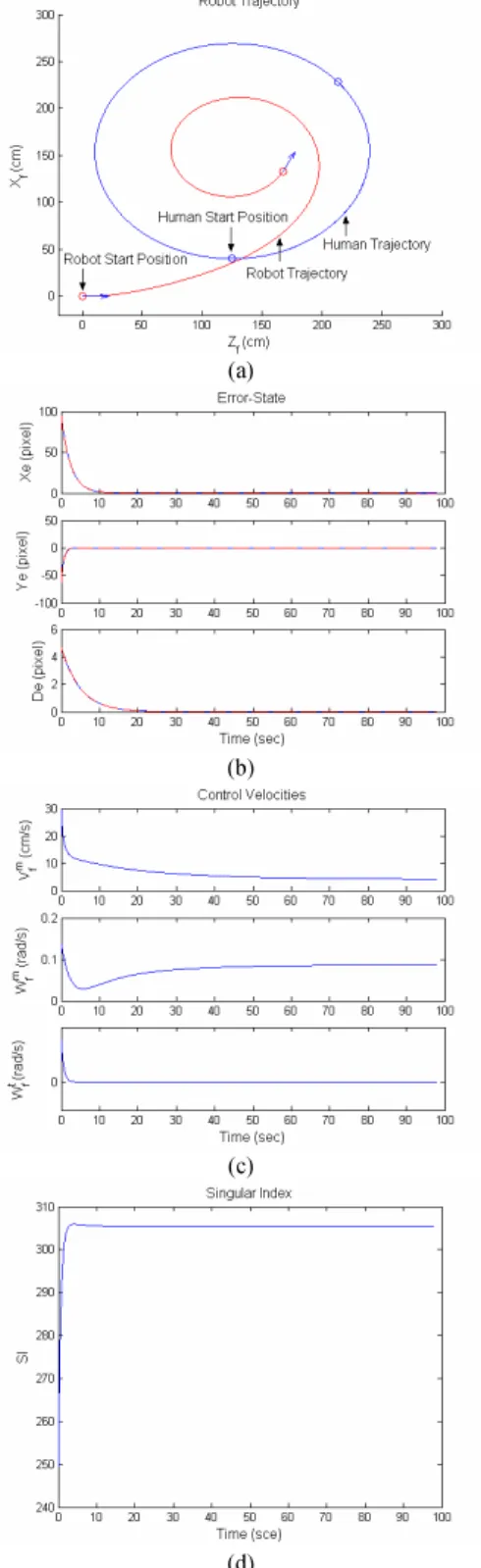
/180 for i=0,1,2,..., and θ0=0. Fig. 4 shows the simulation results of this case. Fig. 4(a) shows the human and tracking robot trajectories in world coordinates. Fig. 4(b) indicates the tracking errors in image plane. According to (8), the transitions of error-state will decay exponentially to zero such thatFig. 3 The experimental mobile robot interacting with a user through face tracking.
TABLE I
PARAMETERSUSEDINTHEEXPERIMENT
Symbol Quantity Description
F 15 cm Width of user’s face
D 40 cm Distance between two
drive wheels )
,
(fx fy (294,312) pixels Focal lengths of camera
in retinal coordinates )
, ,
(xi yi dx (0, 0, 40) Desired state in image plane
) , ,
(ρ1ρ2 ρ3 (1/10, 1/4, 1/20) Three scalar factors
) , ,
(β1 β2 β3 (4, 6, 4) Three positive constants
) , ,
) 0 ( )] 5 exp( ), 2 3 exp( ), 5 2 [exp( ) ( e e t diag t t t X X = − − − . (20)
In Fig. 4(b), the dotted lines represent the theoretical value of (20) while the solid lines illustrate the simulation results of tracking errors. It is clear that the convergence rate of simulation results follows the expected value from (20). Fig. 4(c) shows the command velocities of the tracking robot. Fig. 4(d) depicts the transition of SI value from (10). It shows that the SI value is large enough at every moment, and the matrix
i
B is nonsingular during the visual tracking procedure. B. Experimental Results
In the experiments, the proposed face tracking controller (11) is combined with the proposed robust control law (18) in order to eliminate the quantization uncertainty in the practical system. Because we do not have a design for estimating 3D velocities of user’s face in current work, the velocities of user’s face is neglected in the experiment such that
)
0
,
0
,
0
(
)
,
,
(
z=
h y h x hv
v
v
. (21)This assumption leads to a simplified control law from (11) such that
e
i KX
B
u= −1 , (22)
where matrix B can be termed as image Jacobian, and the i face tracking control problem is reduced to a visual servo control problem [9]. Therefore, the visual servo control problem can be treated as a special case of visual tracking control problem that target is static. The robot adopts the proposed control law through similarity transformation [10].
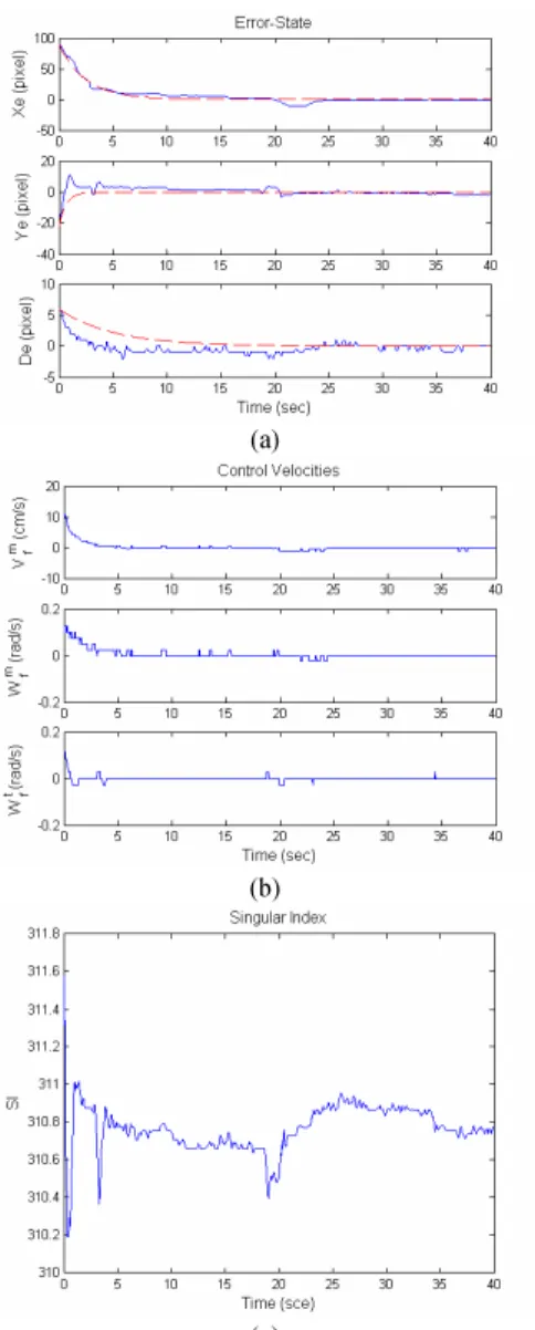
Fig. 5 presents the recorded responses of the mobile robot in the experiment of human-robot interaction. Fig. 5(a) depicts the responses of tracking errors. In this figure, the dotted lines represent the theoretical value of (20), while the solid lines are the experimental results of tracking errors. It can be seen that the convergence rate of experimental results is faster than that of (20). This implies the proposed robust control law (18) not only guarantees the tracking errors to decay to zero asymptotically, but also increases the convergence rate in the practical system. Thus, the tracking performance of the proposed control scheme is verified. Fig. 5(b) shows the control velocities of the tracking robot. Fig. 5(c) illustrates the transition of SI value from (10). We observe that the SI value is large enough at every moment, and thus the matrix B is i nonsingular during the visual tracking procedure.
Fig. 6 shows photos of motion sequences of visual interaction between human and the robot during the visual tracking experiment. In Fig. 6(a), the tracking robot detected the user’s face and started visual tracking interaction. In Figs. 6(b) and (c), the tracking robot moved forward automatically to track the user’s face. In Fig. 6(d), the tracking robot tracked the user successfully and stoped moving forward. Video clips of several visual tracking experiments are available online [11]. Note that in the video, three scalar factors of the visual tracking controller were assigned as (ρ1,ρ2,ρ3)=(15,12,110) in order to increase the response speed of the tracking robot.
(a)
(b)
(c)
(d)
Fig. 4 Simulation results. (a) Both of the human and tracking robot trajectories in world coordinates. (b) Tracking errors in image plane. (c) Control velocities of the center point of tracking robot. (d) Singular index (10) in every moment.
VI. CONCLUSIONS
A novel face tracking interaction controller has been proposed for vision-based human-robot interaction. A face tracking interaction controller has been presented to achieve
(a)
(b)
(c)
Fig. 5 Experimental results. (a) Tracking errors in image plane. (b) Control velocities of the center point of tracking robot. (c) Singular index (10) at each sample instant.
asymptotically stable tracking control of a nonholnomic mobile robot. In order to overcome the problem caused by velocity quantization errors in practical systems, an image-based robust control law is proposed to guarantee the stability necessary condition based on Lyapunov theory. This provides a useful solution for image-based smooth-motion control of mobile robot for human-robot interaction. Simulation and experimental results validate that the proposed control scheme not only solves visual tracking control problem, but also achieves asymptotic convergence. In the future, the robustness issue of parametric uncertainties in the developed visual interaction model will be further investigated. We will also combine the proposed face tracking controller with a human posture recognition system, which can estimate the 3D velocity of a human face, to implement the dynamic face tracking control of a health-care intelligent robot.
ACKNOWLEDGMENT
The authors would like to thank Prof. Ti-Chung Lee for his suggestion for the system modeling in this study. This work was supported by the National Science Council of Taiwan, ROC under grant NSC 94-2218-E-009-008.
REFERENCES
[1] W. Zajdel, Z. Zivkovic, and B. J. A. Kröse, “Keeping track of humans: have I seen this person before?” in Proc. IEEE Intl. Conf. on Rob. and Auto., Barcelona, Spain, 2005, pp. 2081-2086.
[2] A. Mojaev and A. Zell, “Real-time face tracking using discriminator technique on standard PC hardware,” in Proc. IEEE/RSJ Intl. Conf. on Intelligent Rob. and Sys., Sendal, Japan, 2004, pp. 1335-1339.
[3] S. Feyrer and A. Zell, “Detection, tracking, and pursuit of humans with an autonomous mobile robot,” in Proc. IEEE/RSJ Intl. Conf. on Intelligent Rob. and Sys., Kyonju, Korea, 1999, pp. 864-869.
[4] K.-T. Song and W.-J. Chen, “Face recognition and tracking for human-robot interaction,” in Proc. IEEE Intl. Conf. on Sys., Man and Cyber., The Hague, the Netherlands, 2004, pp.2877-2882.
[5] C.-Y. Tsai and K.-T. Song, “Robust Visual Tracking Control of Mobile Robots Based on an Error Model in Image Plane,” in Proc. IEEE Intl. Conf. on Mech. and Auto., Niagara Falls, Canada, 2005, pp. 1218-1223. [6] A. Habed and B. Boufama, “Camera self-calibration: a new approach for
solving the modulus constraint,” in Proc. IEEE Intl. Conf. on Pat. Rec., Cambridge, UK, 2004, pp. 116-119.
[7] J.-J. E. Slotine and W. Li, Applied Nonlinear Control. Englewood Cliffs, NJ: Prentice-Hall, 1991.
[8] K.-T. Song, J.-S. Hu, C.-Y. Tsai, C.-M. Chou, C.-C. Cheng, W.-H. Liu, and C.-H. Yang, “Speaker attention system for mobile robots using microphone array and face tracking,” in Proc. IEEE Intl. Conf. on Rob. and Auto., Orlando, Florida, May 2006, pp. 3624-3629.
[9] S. Hutchinson, G. D. Hager and P. I. Corke, “A tutorial on visual servo control,” IEEE Trans. Robotics and Automation, Vol. 12, No. 5, pp. 651-670, 1996.
[10] C.-Y. Tsai and K.-T. Song, “Visual tracking control of a mobile robot using a new model in image plane,” in Proc. IEEE Intl. Conf. on Adv. Rob., Seattle, WA, USA, 2005, pp. 540-545.
[11] The experiment video website. [Online]. Available: http://isci.cn.nctu.edu.tw/video/FTIC/
(a) (c)
(b) (d)
Fig. 6 Recorded image sequence of interaction between a human and the mobile robot.