大學]
On: 27 April 2014, At: 23:58 Publisher: Taylor & Francis
Informa Ltd Registered in England and Wales Registered Number: 1072954 Registered office: Mortimer House, 37-41 Mortimer Street, London W1T 3JH, UK
Numerical Heat Transfer,
Part A: Applications: An
International Journal
of Computation and
Methodology
Publication details, including instructions for authors and subscription information: http://www.tandfonline.com/loi/unht20
EFFECTS OF LOBE GEOMETRY
ON THE MIXING FLOW IN
MULTILOBE MIXERS
Yeng-Yung Tsui, Po-Wenn Wua
Department of Mechanical Engineering, National Chiao Tung University, Hsinchu 300, Taiwan, Republic of China
Published online: 29 Oct 2010.
To cite this article: Yeng-Yung Tsui, Po-Wenn Wu (2001) EFFECTS OF LOBE GEOMETRY ON THE MIXING FLOW IN MULTILOBE MIXERS, Numerical Heat Transfer, Part A: Applications: An International Journal of Computation and Methodology, 39:1, 61-77, DOI: 10.1080/10407780121487
To link to this article: http://dx.doi.org/10.1080/10407780121487
PLEASE SCROLL DOWN FOR ARTICLE
Taylor & Francis makes every effort to ensure the accuracy of all the information (the “Content”) contained in the publications on our platform. However, Taylor & Francis, our agents, and our licensors make no representations or warranties whatsoever as to the accuracy, completeness, or suitability for any purpose of the Content. Any opinions and views expressed in this publication are the opinions and views of
The accuracy of the Content should not be relied upon and should be independently verified with primary sources of information. Taylor and Francis shall not be liable for any losses, actions, claims, proceedings, demands, costs, expenses, damages, and other liabilities whatsoever or howsoever caused arising directly or indirectly in connection with, in relation to or arising out of the use of the Content.
This article may be used for research, teaching, and private study purposes. Any substantial or systematic reproduction, redistribution, reselling, loan, sub-licensing, systematic supply, or distribution in any form to anyone is expressly forbidden. Terms & Conditions of access and use can be found at http://www.tandfonline.com/page/terms-and-conditions
EFFECTS OF LOBE GEOM ETRY ON THE M IXING FLOW
IN M ULTILOBE M IXERS
Y eng-Yung Tsui and Po-Wenn Wu
Department of Mechanical Engineering, National Chiao Tung University, Hsinchu 300, Taiwan, Republic of China
This study is concerned with a numerical investigation of the mixing ow in multilobe mixers. Predictions are obtained using a nite-volume method which incorporates a second-order difference scheme. The irregular boundaries are tted by curvilinear nonorthogonal grids and the grid points are arranged in the collocated manner. A method is described to generate suitable three-dimensional grids to cover both the lobe region and the mixing duct. Computations are undertaken to examine the effects of lobe geometry on the mixing performance. Results indicated that the convex lobe contour can lead to stronger vortex ow and, thus, better mixing because of its large slope. As for the geometry of the lobe trailing edge, a sinusoidal shape with wide peak region gives rise to well-organized vortices and the mixing performance is enhanced. Also revealed is the mech-anism which, resulting in ef cient mixing in the mixer, is clearly identi ed.
INTRODUCTION
The £ow through a splitter plate (or annular splitter) with convoluted trailing edge is of interest because an array of secondary streamwise vortices of alternating sign are formed after £ow streams, initially divided by the splitter, merge at the end of the splitter. Due to appearance of the vortex £ow, exchange of momentum and energy between the streams is enhanced. It is attractive to apply such a device to, e.g., supersonic ejectors [1] for reducing take-off noise and increasing the thrust, and heat exchangers to augment heat transfer, etc. The study of Werle et al. [2] demonstrated that by rippling the trailing edge, the boundary-layer separation on an airfoil could be alleviated to yield higher lift.
The application of a lobed mixer in turbofan engines has drawn much attention in past years. A schematic sketch of the mixer is shown in Figure 1, in which a high-speed core stream emerging from turbine is mixed with a low-speed stream running out of the fan. The generation of streamwise vortices in the tail duct is due to the radial £ows of opposite direction induced in the lobe, which was evident 1040-7782 /01 $12.00 + .00
61 Received 4 January 2000; accepted 15 March 2000.
This work was supported by the National Science Council, Republic of China, under contract NSC 84-2212-E009-006.
The present address of Po-Wenn Wu is Center for Industrial Safety and Health Technology, Indus-trial Technology Research Institute, Bldg. 51, 195-10 Sec. 4 Chung-Hsing Rd., Chutung Hsinchu, Taiwan 310, Republic of China
Address correspondence to Dr. Y. Y. Tsui, National Chiao Tung University, Department of Mech-anical Engineering, 1001 Ta Hsueh Road, Hsinchu, Taiwan 30050, Republic of China.
in the experiments of Paterson [3]. The formation of the secondary £ow is basically of inviscid nature, evidenced in the study of Barber et al. [4]. However, it should be understood that it is the small-scale turbulent motion embedded in the shear layer
NOM ENCLATURE Zi xk cofactor of Zi xkin the Jacobian of the transformation Zi Zixk J Jacobian of transformation L lobe length M mixedness
Sf source term of the f transport equation
U velocity in the axial direction Ui contravariant velocity in the xi
direction
Z, r, y axial, radial and azimuthal directions, respectively Zi cylindrical coordinates a, b, g metric coef¢cients of the
domain transformation
G circulation
Gf diffusion coef¢cient of the f transport equation xi curvilinear coordinates r density s variance f dependent variable o vorticity O underrelaxation factor Superscripts n, n 1 iteration indices Subscripts i, j, k nodal indices
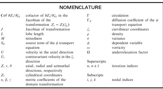
Figure 1. Illustration of the £ow in a multilobe mixer.
shedding from the lobe end that accomplishes the mixing. Thus, an adequate modeling of turbulence characteristics is necessary.
In addition to the most prominent streamwise vortex structure, the velocity difference between the core and fan streams leads to formation of ``normal vortices’’ [5, 6] in the shear layer downstream of the lobe. The scale of the normal vortex is much smaller than that of the streamwise vortex. The roles played by the two types of vortex will be evident later in this study.
Lobe geometries certainly affect performance of the mixer. In order to optimize the mixing process, the design of the mixer lobe has relied heavily on experiments to correlate mixing performance to a variety of geometric parameters. Undoubtedly, this is costly and tedious. Hence, an analytical tool is essential to its development. Some early attempts used simpli¢ed Navier-Stokes solvers and the investigations were restricted to the region downstream of the lobe [7, 8]. More recently, Koutmous and McGuirk [9, 10] modeled the £ow in the lobe by solving full Navier-Stokes equations. Since cylindrical coordinates were adopted in their calculations, grid lines could not coincide with the irregular boundaries of the mixer system. Special treatments, therefore, were enforced at boundaries in their studies.
A prediction method, incorporating three-dimensional curvilinear non-orthogonal coordinates together with a nonstaggered grid arrangement, has been developed by the present authors and used to examine the £ow in the mixing duct. Good agreement with the measurements of Paterson [11] was obtained. However, the success depends on suitable data at the lobe exit provided by experiments as inlet conditions. To remove this restriction, as is done in this study, the com-putational domain should be extended into the lobe, where the inlet conditions are easier to impose. Different from the work of Koutmous and McGuirk, the £ow ¢elds in the lobe and in the mixing duct are solved simultaneously in the present study. A dif¢culty encountered is how to generate suitable grids to ¢t the highly convoluted lobe. Another dif¢culty to overcome is that a converged solution is dif-¢cult to obtain due to the appearance of quite skewed grids near the lobe surface. The way to tackle these dif¢culties is described in the following. The effects of the lobe geometry on the mixing are examined via testing on seven cases with dif-ferent axial contours and trailing edges.
M ATHEM ATICAL M ODEL
The conservation equation for an entity f in a general coordinate system xican be obtained via transformation from cylindrical coordinates:
1 Jr xi rUif 1 Jr xi Gf Jr f xj B i j Sf 1 where Bi j bikbjk 2 and bik rk Zi xk 3
In the above, Uistands for the contravariant velocity in the xidirection, Zidenotes the cylindrical coordinate system (Z, r, y), J is the Jacobian of transformation,
and Sf is the corresponding source term. The symbol Zi xk stands for
the cofactor of Zi xk in the Jacobian, and
rk r 1 i 1 2 i 3 Zi Z r Zi y 4
Detailed expressions for the source term Sfare referred to the previous study [12]. To characterize turbulence the k^e viscosity model of Spalding and Launder [13] was employed. It is recognized that the k^e model can yield good results for most shear-layer £ows. Since the generation of the secondary £ow is an inviscid phenomenon and the mixing process actually takes place in the shear layer between the two streams, it is unlikely that higher-order models are necessary. This model was also used in other studies [10, 14].
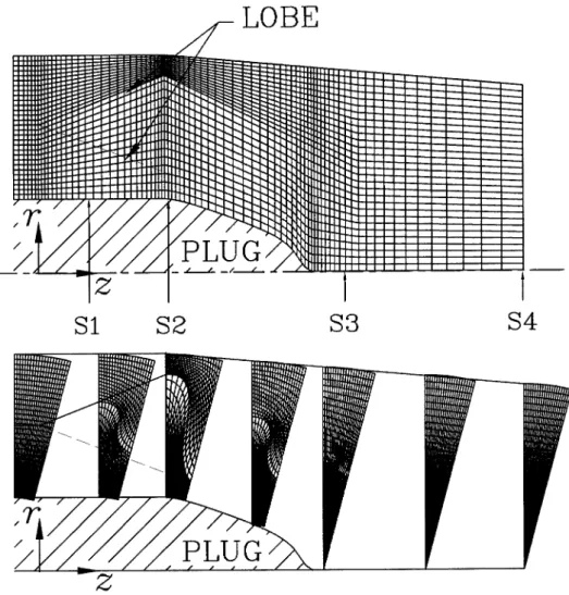
The equations were discretized using the ¢nite-volume method. To alleviate the problem of numerical diffusion, the second-order linear upwind difference [15] was adopted. In the calculation, the velocity components and the pressure were placed at the center of each control volume. This collocated arrangement can lead to oscillatory solutions due to pressure^velocity decoupling. This problem was resolved by Rhie and Chow [16] by employing a special interpolation procedure, based on discretized momentum equations, for evaluating the cell-face velocities. In this pro-cedure the interpolated pressure gradient across the cell face is replaced by that cal-culated from neighboring nodes, as would be done when a staggered grid is used. A common practice employed is to drop the corner-point contributions to the pressure-correction equation during iteration. This practice largely simpli¢es the discrete pressure-correction equation because the number of nodal points involved is reduced to seven for three-dimensional calculations. However, as can be seen in Figure 2, the grids in the lobe region are highly skewed and, as a result, the corner points cannot be ignored because, otherwise, convergence problem may arise. The remedy was to solve the full pressure-correction equation without any simpli¢cation. In this way the total number of points contained is 19. The three-dimensional, 7-point, strongly implicit method of Stone [17] was employed as the iterative solver. Those parts contributed by the corner points were absorbed in the source term and updated during the relaxation.
Another dif¢culty encountered was to generate a suitable three-dimensional grid to cover the lobe and the tail duct. The grid was constructed by ¢rst generating a 2-D grid in a transverse plane at each selected axial location by solving the following transformed Poisson equations [18] individually in the fan and core sides:
axxx 2bxxZ gxZZ J2 Pxx QxZ 5
ayxx 2byxZ gyZZ J2 Pyx QyZ 6
For a domain bounded by x 0 and x x , and Z 0 and Z Z , the following
distribution functions are used to control clustering of grid points near boundaries:
P x Z p1Ze ax p2xe bZ p3Zec x x p4xe d Z Z 7
Q x Z q1Ze ax q2xe bZ q3Zec x x q4xe d Z Z 8
In the equations, a, b, c, and d are positive constants. The coef¢cients, e.g., p1and q1, are determined by speci¢ed spacing along x constant lines between the Z 0 boundary and the next grid nodes together with a given angle formed by the bound-ary lines and the intersected lines, as done by Steger and Sorenson [19].
In the region downstream of the lobe exit, an open boundary extended from the trailing edge of the lobe was speci¢ed to separate the domain into two zones such that the interface gradually changes from the convoluted shape to a circular shape. An iteration between the two zones was undertaken in the way that grid points on
Figure 2. A typical mesh used in the calculation.
the common boundary generated in one zone were imposed as given boundary points for the other zone to carry out grid generation in this zone. When the iterative pro-cess converges, the grid points de¢ning the open common boundary in the two zones match up.
After completing all the 2-D grids at selected locations, the corresponding grid points on the transverse planes were linked together to form a 3-D grid. To ensure smoothness for the grid lines in the axial direction, a slight adjustment of the nodal positions was taken via an implicit relaxation procedure.
xn 1i j k Oxni j k 1 O 1 2 x n 1 i j k 1 xn 1i j k 1 9 yn 1i j k Oyni j k 1 O 12 yn 1i j k 1 yn 1i j k 1 10 A value of 0.9 was used for the underrelaxation factor O.
RESULTS AND DISCUSSION
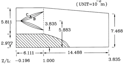
The mixer under consideration is composed of 12 lobes. Because of geometric symmetry, the computational domain is con¢ned in a 15 slice, which covers half a lobe, and symmetrical boundaries form on either side of the sector (see Figure 1). The velocities at the inlet was assumed to be 45 and 90 m/s on the fan and core sides, respectively. The turbulence was about 6% of the inlet velocity, and the tur-bulence length scale was chosen as a fraction of the inlet height. In the ¢rst series of tests, three lobe con¢gurations are considered. As shown in Figure 3, the lobe contour of type A varies in a linear fashion in the axial direction, type B has a con-cave contour, and type C a convex shape. The three lobes have the same convoluted trailing edge. Due to area change in the lobe, the velocity ratio of the core stream to the fan stream decreases from 2 at the inlet to 1.55 at the lobe exit.
A typical grid generated using the method described above is presented in Fig-ure 2. A grid re¢nement test has been conducted for the type A mixer with node numbers ranging from 40,000 to 200,000. The predicted circulation and mixedness, which will be de¢ned below, were not sensitive to the grid density. The resulting differences were within 2%. Therefore, we can be con¢dent that the results presented in the following, obtained using a 57 60 22 (Z, r, y) grid, are adequate for illus-tration of the £ow characteristics.
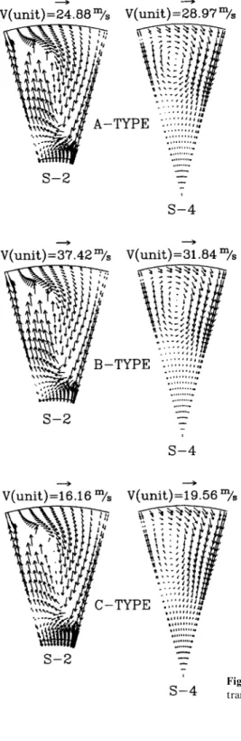
As mentioned in the Introduction, radial velocities of opposite sign are induced by the lobe. This is evidenced in the velocity vectors in the plane at the lobe exit (S2, see Figure 2) in Figure 4. For the sake of better illustration, the dimension in the y direction is doubled (Dy is increased from 15 to 30 ) and the velocity vectors are drawn at every other point. The secondary £ow is transformed to form an axial vortex, which is clear in the outlet plane (S4, see Figure 2) in Figure 4. Examination of the scales shown in the ¢gure indicates that the induced secondary velocities for type B are much stronger than those for type C. This result is not unexpected in view of the larger slope at the lobe exit in the former, due to its convex shape. Flow streamlines will be shaped by the lobe contour, provided no boundary-layer
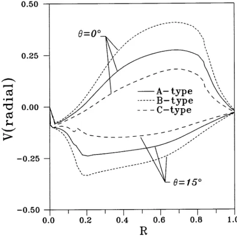
separation occurs. It is seen from Figure 5 that the radial velocities along the two symmetry boundaries at the lobe exit are large for type B and small for type C.
A circulation is de¢ned as G
cV dS 11
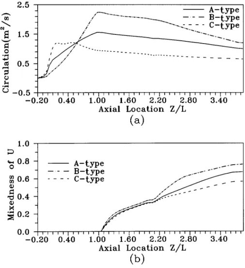
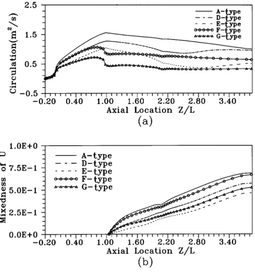
where C denotes the outer circuit of the computational domain on the considered axial planes, being denoted by the dashed lines in Figure 1. It should be understood that by Stokes’s theorem the circulation also stands for the area integration of the axial component of vorticity in the considered cross section. Since velocities vanish on solid walls, the circulation at the lobe exit can be represented by the area enclosed by the two radial velocity pro¢les for y 0 and 15 in Figure 5. Apparently, type B has the largest circulation, type A ranks second, and type C is the worst. The variations of circulation for the three considered cases are shown in Figure 6a. In this and the following ¢gures the axial dimension is normalized using the axial length of the lobe (L). Types A and B reach their peak values of circulation at the lobe exit, while the variation for type C in the lobe is more or less similar to the evolution of its lobe slope. The circulation steadily decays in the mixing duct for all cases.
To evaluate the performance of mixing, a mixedness is de¢ned. Consider the distribution of the axial velocity U over a cross section in the mixing duct. A variance, standing for the deviation from a mean value, is given by
s A U U dA
AU dA
12 where U is the mean axial velocity at the considered cross section. The mixedness is
Figure 3. Illustration of three lobe con¢gurations tested in series I.
Figure 4. Radial and angular velocity vectors in transverse planes for series I.
then de¢ned as
M s0 s
s0 13
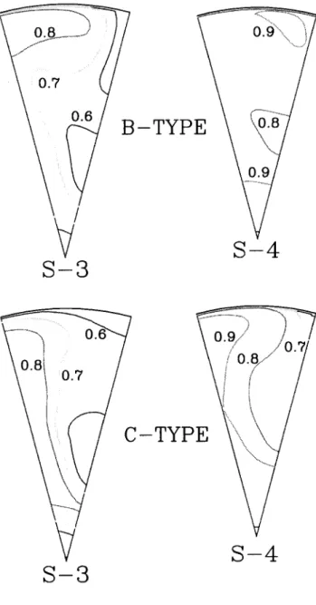
where s0denotes the variance at the lobe exit. The variation of mixedness is exhibited in Figure 6b. It is clear that the high circulation of type B leads to the most ef¢cient mixing while, as expected, the level of mixedness for type C is the lowest. The results indicate that the effectiveness of mixing is closely related to the circulation and, thus, the streamwise vortex £ow. The superiority of type B can be demonstrated in the axial-velocity contour plots shown in Figure 7. In this ¢gure the velocities are normalized by the intake velocity of the core stream (90 m/s). It is apparent that the axial velocity at the exit plane (S-4) is much more uniformly distributed for the type B.
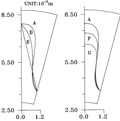
In the second series of tests the lobe contour remains linear like type A, but the shape of the convoluted trailing edge is different. As seen in Figure 8, type E is of triangular form, whereas the geometry of type D is between type A and type E. These two types have the same lobe penetration as type A. The ratio of the mean
Figure 5. Radial velocity distribution along the symmetry lines at the lobe exit for series I.
axial velocity at the lobe exit for the core stream to that for the fan stream is increased from 1.5 for the baseline case (type A) to 2 for type D and 2.75 for type E, due to the area change in lobe passages. Also seen in this ¢gure, the convoluted shapes for types F and G are similar to that of type A, but with lower lobe penetration. It is interesting to compare the performance of types D and E with those of types F and G, respectively, because their lobe exit areas and mean exit velocities for the fan and core streams are nearly identical.
Figures 9a and 9b reveal that both the circulation and mixedness decrease when comparing with the baseline case. However, it should be understood that the cause of the superior performance for type A is mainly ascribed to the low initial variance at the lobe exit due to the smaller velocity difference between the two streams in this mixer.
Figure 6. Axial variation of (a) circulation and (b) mixedness for series I.
Figure 7. Normalized axial velocity contours in transverse planes for series I.
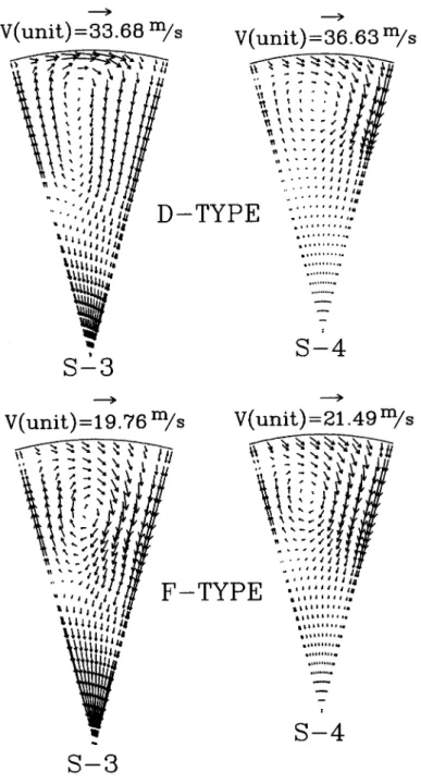
Comparing types D and F indicates that the smaller lobe penetration and, thus, the smaller lobe slope of the latter lead to a lower level of circulation in the mixing duct. But the effectiveness of mixing is higher for type F. To illustrate the cause of better performance for type F, Figure 10 is prepared. It is apparent that although the D-type lobe induces larger secondary velocities, its vortex structure is poorly organized because the rotating center is highly elongated, preventing the high-speed core £ow from penetrating into the fan side and mixing with the low-speed £ow. It can also be identi¢ed from the ¢gure that the strong secondary £ow induced on the core side in the type D mixer rotates clockwise from the left symmetry bound-ary to the upper shroud at the S3 station and reaches the right symmetry boundbound-ary at the outlet plane (S4). Based on the understanding that the circulation is simply equal to the line integral of the radial velocity along the two symmetry boundaries, it is not surprising that the calculation shown in Figure 9a tends to ascend in the late mixing region near the outlet.
The above observations are equally applicable to the mixers of type E and type G, with the situation being even serious.
As mentioned in the Introduction, the mixing actually takes place in the interfacial layer between the two streams, formed downstream of the lobe trailing edge via turbulent diffusion. The mechanism causing mixing enhancement by the
Figure 8. Lobe trailing edges for test series II.
axial vortex, which has been the subject of a previous study [20] by the authors, can be illustrated in Figure 11. The contact surface between the two streams is distorted and elongated by the induced rotating £ows. As a consequence, the length scale of the interfacial layer is largely increased. The velocity gradient is smoothed out in the shear layer and its thickness scale is increased due to turbulent motion. There are two sources to generate turbulence: axial vorticity and normal vorticity. It has been pointed out that the circulation stands for the sum of axial velocities in the considered cross section. The normal vorticity is de¢ned as
on o2r o2y 1 2 14
where or and oy are the vorticity components in the radial and circumferential
Figure 9. Axial variation of (a) circulation and (b) mixedness for series II.
Figure 10. Radial and angular velocity vectors in transverse planes for series II.
directions. Large normal vorticity is produced in the shear layer due to velocity gradients. Figures 12a and 12b present axial variation of the total normal vorticity and total turbulent kinetic energy integrating over each cross-sectional area. The large velocity differences for types E and G give rise to higher levels of normal vorticity and turbulence. The thickness scale of the mixing shear layer is greater in these two cases, but their length scale is much smaller than the other cases.
CONCLUSION
A numerical method incorporating curvilinear coordinate system along with collocated grid arrangement has been adopted to examine the effects of lobe geometry on the mixing £ow in multilobe mixers. Results have shown the following main ¢ndings.
1. The streamwise vortex generated in the multilobe mixer helps promote the mixing process. The length scale of the contact surface between the two
Figure 11. Schematic illustration of the mixing process.
streams is enlarged via distortion and elongation by the secondary £ow transport, while the turbulence produced by the normal vorticity as well as the streamwise vorticity increases the thickness scale of the shear layer. Among these two, the former scale dominates the mixing process. 2. To yield a strong streamwise vortex, the slope at the exit of the lobe
should be as large as possible, provided that there is no separation taking place in the lobe. Thus, a concave lobe shape is preferred to the convex shape.
3. The shape of the trailing edge also affects mixing effectiveness. A sinusoidal shape with a wide peak region is preferred because it leads to better-organized vortex £ows.
Figure 12. Axial variation of (a) normal vorticity and (b) turbulence intensity for series II.
REFERENCES
1. T. J. Barber and O. L. Anderson, Computational Study of a Supersonic Mixer-Ejector Exhaust System, J. Propulsion Power, vol. 8, no. 5, pp. 927^934, 1992.
2. M. J. Werle, R. W. Paterson, and W. M. Presz, Jr., Trailing-Edge Separation/Stall Alleviation, AIAA J., vol. 25, no. 4, pp. 624^626, 1987.
3. R. W. Paterson, The Turbofan Mixer Nozzle Flow FieldöA Benchmark Experimental Study, ASME J. Eng. Gas Turbine Power, vol. 106, pp. 692^698, 1984.
4. T. J. Barber, G. L. Muller, S. M. Ramsay, and E. M. Murman, Three-Dimensional Inviscid Flow in Mixers, Part II: Analysis of Turbofan Forced Mixer, J. Propulsion
Power, vol. 2, no. 4, pp. 339^344, 1986.
5. T. A. Manning, Experimental Studies of Mixing Flows with Streamwise Vorticity, M.S. thesis, Massachusetts Institute of Technology, Cambridge, MA, 1991.
6. D. C. McCormick and J. C. Bennett, Jr., Vortical and Turbulent Structure of a Lobed Mixer Free Shear Layer, AIAA J., vol. 32, no. 9, pp. 1852^1859, 1994.
7. S. F. Birch, G. C. Paynter, D. B. Spalding, and D. G. Tatchell, An Experimental and Numerical Study of the 3-D Mixing Flows of a Turbofan Engine Exhaust System, AIAA Paper 77-204, 1977.
8. L. A. Povinelli and B. H. Anderson, Investigation of Mixing in a Turbofan Exhaust Duct, Part II: Computer Code Application and Veri¢cation, AIAA J., vol. 22, no. 4, pp. 518^525, 1984.
9. P. Koutmos and J. J. McGuirk, Turbofan Forced Mixer/Nozzle Temperature and Flow Field Modeling, Int. J. Heat Mass Transfer, vol. 32, no. 6, pp. 1141^1153 , 1989. 10. P. Koutmos and J. J. McGuirk, CFD Predictions of Lobed Mixer Performance, Comput.
Meth. Appl. Mech. Eng., vol. 122, pp. 131^144, 1995.
11. R. W. Paterson, Turbofan Forced Mixer-Nozzle Internal FlowField IöA Benchmark Experimental Study, NASA Contractor Report 3492, 1982.
12. Y.-Y. Tsui, P.-W. Wu, and C.-W. Liao, Flow Modeling in Turbofan Mixing Duct, Numer.
Heat Transfer A, vol. 26, no. 2, pp. 219^236, 1994.
13. B. E. Launder and D. B. Spalding, The Numerical Computation of Turbulent Flows,
Comput. Meth. Appl. Mech. Eng., vol. 3, pp. 269^289, 1974.
14. J. P. Kreskovsky, W. R. Briley, and H. McDonald, Investigation of Mixing in a Turbofan Exhaust Duct, Part I: Analysis and Computational Procedure, AIAA J., vol. 22, no. 3, pp. 374^382 , 1984.
15. Y.-Y. Tsui, A Study of Upstream-Weighted High-Order Differencing for Approximation to Flow Convection, Int. J. Numer. Meth. Fluids, vol. 13, pp. 167^199, 1991.
16. C. M. Rhie and W. L. Chow, Numerical Study of the Turbulent Flow Past an Airfoil with Trailing Edge Separation, AIAA J., vol. 21, no. 11, pp. 1525^1532 , 1983.
17. H. L. Stone, Iterative Solution of Implicit Approximations of Multidimensional Partial Differential Equations, SIAM J. Numer. Anal., vol. 5, pp. 530^558, 1968.
18. J. F. Thompson, Numerical Grid Generation-Foundations and Applications, North-Holland, New York, 1985.
19. J. L. Steger and R. L. Sorenson, Automatic Mesh-Point Clustering near a Boundary in Grid Generation with Elliptic Partial Differential Equations, J. Comput. Phys., vol. 33, no. 3, pp. 405^410 , 1979.
20. Y.-Y. Tsui and P.-W. Wu, Investigation of the Mixing Flow Structure in Multilobe Mixers, AIAA J., vol. 35, no. 7, pp. 1386^1391 , 1996.