Flexible and reflective polarizer-free liquid crystal displays
using dye-doped liquid crystal gels
Yi-Hsin Lin, Jhih-Ming Yang
Department of Photonics and Institute of Electro-Optical Engineering, National Chiao
Tung University, 1001 Ta Hsueh Rd., Hsinchu 30050, Taiwan
Shie-Chang Jeng, Yan-Rung Lin, Chi-Chang Liao
Electronics&Optoelectronics Research Laboratories,
Industrial Technology Research Institute, Hsinchu 310, Taiwan
Abstract
A flexible and reflective polarizer-free display using dye-doped liquid crystal (LC) gels is demonstrated. The electro-optical performances of both scattering and absorption based dye-doped LC gels depend on curing temperatures. The dye-doped LC gel shows good reflectance ~55%, good contrast ratio~450:1 and fast response~6.5ms at curing temperature 10 oC when UV curing intensity is 2.6 mW/cm2. The EO performance depends on the curing temperature. The hysteresis is independent of sampling time duration. The bending curvature is 21 mm. The response of dye-doped LC gels is faster under bending due to the bending-induced sheared force of polymer networks. The dye-doped LC gels open a new window for trim-able electronic papers, decorative displays and switchtrim-able curtains.
Keywords: liquid crystal, polarizer-free, flexible display, Guest-host.
1. INTRODUCTION
Paper-like flexible displays are roll-able, bendable, trim-able, and conformable. The applications are electronic paper, electronic tag, and decorative displays[1]. Many liquid crystal (LC) technologies and non-liquid crystal technologies have been applied to to achieve transmissive type or reflective type flexible displays. For example, polymer-dispersed liquid crystals (PDLC)[1-6], cholesteric liquid crystals[1,7-11], and single-substrate LCDs using photoenforced stratification[1,12-14] or using LC/polymer composites[15-18], electrophoretic imaging [1,19-21], Gyricon[1,22], and organic light-emitting diode (OLED)[1,23-27]. In liquid crystal-based flexible displays, bistability and colors of cholesteric liquid crystals limits the application due to the complexity of driving and color shift at off angle. By combining dye absorption and scattering, contrast ratio of dye-doped PDLC is poor[28-29] because the dye solubility with polymer matrix, the order parameter of dye and dichroic ratio (typically ~10:1) of dye are the factors to limit the contrast ratio of dye-doped PDLC. Recently, we have developed a new polarizer-free LCD using a dye-doped dual-frequency liquid crystal (DFLC) gel on the ITO-only glass substrates [30-31]. Without polarizers, the optical efficiency is high and viewing angle is wide. Although its contrast ratio reaches ~150:1 and response time ~6 ms under frequency modulation, the frequency driving scheme, high driving voltage (~30 Vrms) and unavoidable dielectric heating effect.[32-33] need to be overcome for TFT-LCDs and flexible displays applications.
In this paper, we demonstrate a reflective and flexible display using dye-doped LC gels which is polarizer-free, fast response, high contrast. The normally white gels exhibit ~55% reflectance, ~450:1 contrast ratio, ~6.4 ms response time, and ~30 Vrms at f=1 kHz driving voltage at curing temperature 10 oC. The EO performance depends on the curing temperature. The hysteresis is independent of sampling time
L.Y*V
— lliI
duration. The bending curvature is 21 mm. The response of dye-doped LC gels is faster under bending due to the bending-induced sheared force of polymer networks. A single pixel flexible reflective display using such dye-doped LC gels are also demonstrated under bending
2. SAMPLE PREPARATION
The dye-doped LC mixture consists of negative nematic liquid crystal ZLI-4788 (Merck, ne= 1.6567, ∆n=0.1647 at λ=589 nm; ∆ε= -5.7 at f= 1 kHz) , a diacrylate monomer (bisphenol-A-dimethacrylate)and a dichroic dye S428 (Mitsui, Japan) at 90:5:5 wt% ratios. The dye-doped LC mixture was then injected into an empty cell consisting of two glass substrates or flexible substrates whose inner surfaces were coated with a thin conductive layer, indium-tin-oxide (ITO) on glass substrates and indium-zinc-oxide (IZO) on the flexible substrates, electrode and polyimide (PI) layer without rubbing treatment. The PI layer provides vertical alignment for the LC directors. The cell gap was 5 µm. The filled cell was irradiated by a UV light (λ~365 nm, I~3 mW/cm2). Both cells were cured by the UV light at a fixed temperature for 1.5 hr. After photo-polymerization, the formed chainlike polymer networks are along the z direction because the LC directors are aligned perpendicular to the glass substrates during the UV curing process, as shown in Fig. 1(a).
The structure and operation principles of the dye-doped LC gel are shown in Fig. 1(a) and Fig. 1(b). At V=0, the cell does not scatter light and the absorption is rather weak due to the vertically aligned polymer networks, liquid crystal directors and dye molecules. Therefore, the display has high reflectance. When we apply a high voltage at f= 1 kHz in the dye-doped LC gel, the negative liquid crystals and dye molecules are reoriented in the x-y plane, as Fig. 1(b) depicts. The polymer network scatters light strongly. Since the alignment layer has no rubbing treatment, the absorption has no preferred direction; therefore, the display appears black because of the strong light scattering and dye absorption.
~
ITO glass substrate
Diffusive reflector LC Dye Alignment layer Polymer network
~
x x z~
ITO glass substrate
Diffusive reflector LC Dye Alignment layer Polymer network
~
~
~
ITO glass substrate
Diffusive reflector LC Dye Alignment layer
Polymer network
~
ITO glass substrate
Diffusive reflector LC Dye Alignment layer Polymer network
~
x x z x x zFig. 1. Schematic structure of dye-doped liquid crystal display at (a) voltage-off state and (b) voltage-on state. 3. EXPERIMENTAL RESULTS
Figures 2 shows the morphologies of the abovementioned UV-cured dye-doped LC gels observed from a polarized optical microscope with a single polarizer only. The top region in Fig. 2 was applied 30 Vrms at f=1 kHz and the bottom region was applied 0Vrms. At 30 Vrms, it shows the fine domain textures of the polymer networks, and red color because of dye molecules. Our LC cell shows good dark and bright states although the dark state up to now is redish, not truly black.
30 V rms
0 V rms 30 V rms
0 V rms
We use the typical reflectance measurement to measure the electro-optical properties of dye-doped LC gels. Because the guest-host system we employed appears dark red rather than black, we used an unpolarized green He-Ne laser (λ=543.5 nm, Melles Griot, Model 05-LGR-173) instead of a white light source for characterizing the device performances. A dielectric mirror was placed behind the cell so that the laser beam passed through the cell twice. A large area photodiode detector (New Focus, Model 2031) was placed at ~25 cm (the normal distance for viewing a mobile display) behind the sample which corresponds to ~2o collection angle. A computer controlled LabVIEW data acquisition system was used for driving the sample and recording the light reflectance.
0.0 0.2 0.4 0.6 0.8 1.0 0 10 20 30 Voltage, Vrms R efl ec ta nc e 10℃ 20℃ 30℃ 40℃
(a)
0 0.2 0.4 0.6 0.8 1 0 200 400 600 800 1000 Time, ms R efl ectan ce -150 -100 -50 0 50 Vo lt ag e, Vrms(b)
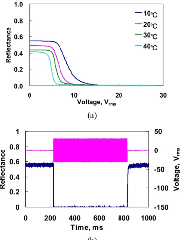
Fig. 3. (a)Voltage-dependent reflectance at various curing temperature. (b) The response time of dye-doped LC gels is ~0.4 ms for rising time and ~6 ms for decay time. Curing temperature was 10 oC.
Figure 3 (a) plots the voltage-dependant reflectance of the dye-doped LC gels at different curing temperatures as the UV curing intensity was 3 mW /cm2. The reflectance is normalized to that of a pure LC cell with the same cell gaps. In Fig. 3(a), the reflectance decreases gradually as V>Vth because of the increase of the scattering and the absorption. As curing temperature decreases, the increases (~40% to ~55%) of maximum reflectance at 0 Vrms result from the better vertical alignment of LC directors, dye molecules and polymer networks at low curing temperature. The contrast ratio (CR) is defined as reflectance ratio of 0 Vrms to 30 Vrms. The CR is ~450: 1 at 10 oC, 250: 1 at 20 oC, 200: 1 at 30 oC, and 300: 1 at 40 oC. The contrast ratio decreases as T< 30oC and then increases as T>30oC. That is because the increase of a curing temperature results in larger polydomains; therefore, the contrast ratio and threshold voltage decrease. When the temperature is higher than 30oC, we found the cell has dynamic scattering to help rebooting the contrast ratio. The reason why the larger domain has the dynamic scattering is still
unclear. Response time is also an important parameter for guest-host displays. The response time of the dye-doped LC gels was measured using 30 Vrms squared pulses with time duration 600ms at f=1 kHz. The rise times and decay times of dye-doped LC gels at curing temperature 10 oC is shown in Fig. 3(b). The rise time is ~ 0.4 ms and the decay time is ~6 ms. A typical response time of a guest-host display is around 50 ms. The response time of our dye-doped LC gel is ~7x faster because polymer network helps LC directors to relax back.
Figure 4(a) plots the voltage-dependant reflectance of dye-dope LC gels under different sampling time duration. The hysteresis of dye-dope LC gels is independent of sampling time duration when the voltage is ramped up and down. Typically the hysteresis of LC and polymer composite system is larger with smaller sampling time duration. The transmission spectrum of dye-doped LC gels is also shown in Fig. 4(b). The dye-doped LC gel shows dark red, not black at 30 Vrms
0 0.2 0.4 0.6 0.8 1 0 10 20 30 Voltage,Vrms R efl ectan ce 100ms 400ms 600ms 0 0.2 0.4 0.6 0.8 1 0 10 20 30 Voltage,Vrms R efl ectan ce 100ms 400ms 600ms
(a)
0 200 400 600 800 300 400 500 600 700 800 Wavelength, nm Int ens it y 0V 30V(b)
Fig. 4 (a)The voltage-dependant reflectance of dye-dope LC gels with increasing voltage and decreasing voltagen at different sampling time duration. The curing temperature was 20 oC. (b) The transmission spectrum of dye-dope LC gels. The curing temperature was 20 oC.
To prove principles, we also fabricated a single pixel polarizer-free reflective LCD using the dye-doped LC gels in glass substrates, as shown in Fig. 5(a). To avoid specular reflection, we laminated a diffusive reflector, a white paper, on the backside of the bottom glass substrate. The ambient white light was used to illuminate the samples. The voltage is applied in the middle squared region which is also ITO patterned region. Since no polarizer is used, the optical efficiency is high and the viewing angle is not limited by a polarizer. A single pixel polarizer-free reflective and flexible LCD using dye-doped LC gels is shown in Fig. 5 (c) and (d). The flexible substrates are provided by EOL/ITRI [34-35]. IZO was over coated on the top of flexible substrates made by polycarbonate with thickness 120 µm. The cross shaped microstructures
+
+
!oc
made by photo-spacers were developed on the flexible substrates to keep the cell gap under bending. The width of photo-spacers is 10 µm and the pitch of photo-spacers is 430 µm. We also laminated a white paper as a diffusive reflector on the backside of the bottom flexible substrate. The ambient white light was used to illuminate the sample. The vertically aligned polymer networks can further help to maintain the cell gap under bending. However, the CR is slightly degraded because of two reasons: the microstructures of photo-spacers and the UV absorption of substrates. The absorption of UV light by the flexible substrate results in the weaker UV intensity and slightly increases of curing temperature. Those two reasons result in slower response as well.
Figure 6(a) is thetransmission as a function of radius of curvature under bending at voltage-off state. The transmission of dye-doped LC gels is almost the same as the radius of curvature is larger than 21 mm. The decay time decreases when the radius of curvature is smaller than 30 mm. The reason why the faster response of bending dye-doped LC gels may be due to the external sheared force of the polymer networks.
100µm 100µm
(a) (b)
(c) (d)
Fig. 5. (a)A single pixel polarizer-free reflective LCD using the dye-doped LC gels in glass substrates.A white paper was used as a diffusive reflector.The curing temperature was 10 oC. (b) A morphology of plastic substrate observing under a microscopy. (c)(d) A single pixel polarizer-free reflective and flexible LCD using dye-doped LC gels at 0 and 30 Vrms. A white paper was used as a diffusive reflector.
0 1 2 3 4 0 30 60 90 120 150 Radius of curvature, mm T ran s m issi o n , a .u . 0V 30V
(a)
0 0.2 0.4 0.6 0.8 1 0 30 60 90 120 150 Radius of curvature, mm R ise ti me, ms 0 5 10 15 20 25 30 D ecay ti me, ms Rise time Decay time
(b)
Fig. 6. (a)The transmission as a function of bending radius curvature of a single pixel dye-doped LC gels. (b) The response time as a function of bending radius curvature. The curing temperatures were 10 oC.
4. CONCLUSION
We have demonstrated a high-contrast and polarizer-free reflective and flexible LCDs using dye-doped LC gels. The increase of the curing temperature resulting in larger domain sizes affects EO properties of dye-doped LC gels. Since no polarizer is needed, the viewing angle is wide and the brightness is high. The contrast ratio is 450:1 at 30 Vrms and the response time is around 6.4 ms at curing temperature 10oC. The maximal reflectance is about 55%. The hysteresis is independent of sampling time duration. The curing temperature is low (<40oC) which is more favorable for the flexible displays. That is because the polymer networks vertical to the substrate and the micro-structures of photo-spacer help to maintain the cell gap during the bending. The radius of bending curvature is 21 mm. However, the issues we have to overcome are the high driving voltage and red color of dye-doped LC gels. Improving LC materials with larger value of dielectric anisotropy and dye could lower driving voltage and adjust the color. The potential application is electronic papers and switchable curtains.
Acknowledgments
The authors are indebted to Dr. Yung-Hsun Wu (Innolux, Taiwan) for technical discussions. This work is supported by Electronics & Optoelectronics Research Laboratories, Industrial Technology Research Institute (Taiwan) and National Science Council (NSC) in Taiwan under project number: 96-2112-M-009-019-MY2.
REFERENCES
1. G. P. Crawford, Flexible Flat Panel Displays, (England: Wiley, 2005).
2. P. Mach, S. J. Rodriguez, R. Nortrup, P. Wiltzius, J. A. Rogers JA, “Monolithically integrated, flexible display of polymer-dispersed liquid crystal driven by rubber-stamped organic thin-film transistors,” Appl. Phys. Lett. 78, 3592-3594 (2001)
3. C. D. Sheraw, L. Zhou, J. R. Huang,, Gundlach DJ, T. N. Jackson, M. G. Kane, I. G. Hill, M. S. Hammond, J. Campi, B. K. Greening, J. Francl, J. West, “Organic thin-film transistor-driven polymer-dispersed liquid crystal displays on flexible polymeric substrates,” Appl. Phys. Lett. 80, 1088-1090 (2002).
4. D. Hohnholz, H. Okuzaki, A. G. MacDiarmid, “Plastic electronic devices through line patterning of conducting polymers,” Adv. Funct. Mater. 15, 51-56 (2005)
5. E. A. Buyuktanir, M. Mitrokhin, B. Holter, A. Glushchenk, J. L. West, “Flexible bistable smectic-A polymer dispersed liquid crystal display,” Jpn. J. Appl. Phys. Part 1 45, 4146-4151 (2006)
6. P. C. Wang , and A. G. MacDiarmid , “Integration of polymer-dispersed liquid crystal composites with conducting polymer thin films toward the fabrication of flexible display devices,” Displays 28 101-104 (2007)
7. S. T. Wu and D. K. Yang, Reflective liquid crystal displays, (New York: Wiley, 2001).
8. D. K. Yang, J. L. West, L. C. Chien, and J. W. Doane, “ Control of reflectivity and bistability in displays using cholesteric liquid crystals,” J. of Appl. Phys. 76, 1331-1333 (1994)
9. A. Khan, I. Shiyanovskaya, T. Schneider, N. Miller, T. Ernst, D. Marhefka, F. Nicholson, S. Green, G. Magyar, “Reflective cholesteric displays: from rigid to flexible,” J. of Soc. Inform. Displays 13, 169-474 (2005)
10. K. Chari, C. M. Rankin, D. M. Johnson, T. N. Blanton, R. G. Capurso, “Single-substrate cholesteric liquid crystal displays by colloidal self-assembly,” Appl. Phys. Lett. 88, 043502 (2006)
11. A. Khan, I. Shiyanovskaya, T. Schneider, E. Montbach, D. J. Davis, N. Miller, D. Marhefka, T. Ernst, F. Nicholson, J. W. Doane, “Progress in flexible and drapable reflective cholesteric displays,” J. of Soc. Info. Displays 15, 9-16 (2007)
12. R. Penterman, S. L. Klink, H. de Koning, G. Nisato, D. J. Broer, “Single-substrate liquid-crystal displays by photo-enforced stratification,” Nature 417, 55-58 (2002)
13. P. Raynes, “Liquid crystal painting,” Nature, 417, 28–29 (2002)
14. J. P. A. Vogels, S. I. Klink, R. Penterman, H. D. Koning, E. E. A. Huitema, and D. J. Broer, “Robust flexible LCDs with paintable technology,” Soc. Inform. Display Tech. Dig. 35, 767–769 (2004). 15. I. Kim, J. H. Kim, D. Kang, D. M. Agra-Kooijman, and S. Kumar, “Fabrication of electro-optic
devices using liquid crystals with a single glass substrate,” J. Appl. Phys., 92 7699–7701 (2002). 16. J. H. Kim, V. Vorflusev, S. Kumar, “Single glass substrate LCDs using a phase separated composite
organic film method,” Displays 25, 207-213 (2004)
17. Y. H. Lin, H. Ren, S. Gauza, Y. H. Wu, Y. Zhao, J. Fang, and S. T. Wu, “IPS-LCD using a glass substrate and an anisotropic polymer film,” J. Display Technology 2, 21-25 ( 2006).
18. H. W. Ren, S. T. Wu, Y. H. Lin, “Single glass substrate liquid crystal device using electric field-enforced phase separation and photoinduced polymerization,” Appl. Phys. Lett. 90, 191105 (2007) 19. B. Comiskey, J. D. Albert, H. Yoshizawa, J. Jacobson, “An electrophoretic ink for all-printed
reflective electronic displays,” Nature 394, 253-255 (1998)
20. G. H. Gelinck, H. E. A. Huitema, E. Van Veenendaal, E. Cantatore, L. Schrijnemakers , J. B. P. H Van der Putten, T. C. T. Geuns, M. Beenhakkers, J. B. Giesbers, B. H. Huisman, E. J. Meijer, E. M. Benito, F. J. Touwslager, A. W. Marsman, B. J. E Van Rens, D. M. De Leeuw, “Flexible active-matrix displays and shift registers based on solution-processed organic transistors,” Nature Mater. 3, 106-110 (2004)
21. J. Daniel, A. C.Arias, W. Wong, R. Lujan, S. Ready, B. Krusor, R. Street, “Jet-printed active-matrix backplanes and electrophoretic displays,”Jpn. J. Appl. Phys. Part 1 46, 363-1369 (2007)
22. J. M. Crowley, N. K. Sheridon, L. Romano, “Dipole moments of gyricon balls,” J. Electrostat. 55, 247-259 (2002)
23. G. Gu, P. E. Burrows, S. Venkatesh, S. R. Forrest, M. E. Thompson, “Vacuum-deposited, nonpolymeric flexible organic light-emitting devices,” Opt. Lett. 22, 172-174 (1997)
24. P. E. Burrows, G. Gu, V. Bulovic, Z. Shen , S. R. Forrest, M. E. Thompson, “Achieving full-color organic light-emitting devices for lightweight, flat-panel displays,” IEEE T Electron Dev. 44, 1188-1203 (1997)
25. A. N. Krasnov, “High-contrast organic light-emitting diodes on flexible substrates,” Appl. Phys. Lett. 80, 3853-3855 (2002)
26. A. Sugimoto, H. Ochi, S. Fujimura, A. Yoshida, T. Miyadera, M. Tsuchida, “Flexible OLED displays using plastic substrates,” IEEE J. Sel. Top. Quantum Electron 10,107-114 (2004)
27. L. S. Zhou, A. Wanga, S. C. Wu, J. Sun, S. Park, T. N. Jackson, “All-organic active matrix flexible display,” Appl. Phys. Lett. 88 083502 (2006)
28. P. S. Drzaic, Liquid Crystal Dispersions, (Singapore: World Scientific, 1995)
29. Y. H. Lin, H. Ren, and S. T.Wu, “High contrast polymer-dispersed liquid crystal in a 90 Cell,” Appl. Phys. Lett. 84, 4083–4085 (2004).
30. Y. H. Lin, H. Ren, S. Gauza, Y. H. Wu, X. Liang , and S. T.Wu, “Reflective direct-view displays using a dye-doped dual-frequency liquid crystal gel,” IEEE/OSA J. Display Technology 1, 230-233
(2005)
31. Y. H. Lin, H. Ren, S. Gauza, Y. H. Wu, Y. Zhou and S. T.Wu, “High contrast and fast response polarization-independent reflective display using a dye-doped dual-frequency liquid crystal gel,” Mol. Cryst. Liq. Cryst 453, 371-378 (2006)
32. C. H. Wen and S. T. Wu, “Dielectric heating effects of dual-frequency liquid crystals,” Appl. Phys. Lett. 86, 231104 (2005)
33. Y. Yin, S. V. Shiyanovskii, and O. D. Lavrentovich, “Electric heating effects in nematic liquid crystals,” J. Appl. Phys. 100, 024906 (2006)
34. K. H. Liu, W. Y. Chou, C. C. Liao, C. T Ho, H. P. Shieh, “ Microcell liquid crystal film for high-contrast flexible display applications,” Jpn. J. Appl. Phys. 45, 7761-7765 (2006)
35. K. H. Liu, C. Y. Lee, C. T Ho, H. L. Cheng, S. T Lin, H. C. Tang, C. W. Kuo, C. C. Liao, H. P. Shieh, and W. Y. Chou, “Innovative plasma alignment method in flexible liquid crystal display films,” Electrochem. Solid State Lett. 10, J132-J135 (2007)
36. I. C. Khoo, and S. T. Wu, Optics and Nonlinear Optics of Liquid Crystals, (Singapore: World Scientific, 1993)