On the other hand, several MIMO configurations have been con-sidered to compare performances in terms of channel capacity includ-ing electromagnetic parameters of the antenna, such as radiation patterns and mutual coupling. The Spatial Channel Model from 3 GPP has been used for the simulations. Higher capacity has been obtained in the configuration where the two antennas has been placed in parallel with a spacing of 0.4 wavelengths within a PDA, mainly due to the lower mutual coupling and thus to uncorrelation between MIMO subchannels. Moreover, the radiation pattern for both anten-nas has been measured and MIMO channel measurement have been carried our in an indoor environment, obtaining in average higher capacity in the case of the designed PIFAs.
ACKNOWLEDGMENT
The authors wish to thank S.R.F. Moyano, from Dragados Indus-trial, especially to Mr. Alberto Martı´nez Ollero, for the support of this research work conducted as part of the PIDEA SMART project and partially funded by PROFIT FIT-330210 –2005-107. The electromagnetic simulations presented in this article have been realized using CST Microwave Studio version 5.0 under a co-operation agreement between Computer Simulation Technology (CST) and Universidad Polite´cnica de Madrid.
REFERENCES
1. G. Foschini and M. Gans, On limits of wireless communications in a fading environment when using multiple antennas, Wireless Personal Commun 6 (1998), 311–335.
2. A.J. Paulraj, D.A. Gore, R.U. Nabar, and H. Bo¨lcskei, An overview of MIMO communications—A key to gigabit wireless, Proceedings of the IEEE 92 (2004), 198 –217.
3. K.-L. Wong, Planar antennas for wireless communications, Wiley, New Jersey, 2003.
4. P. Salonen, M. Keskilammi, and M. Kivikoski, New slot configurations for dualband planar inverted-F antenna, Microwave Opt Technol Lett 28 (2001), 293–298.
5. 3GPP, Spatial channel model for multiple input multiple output (MIMO) simulations, 3GPP TR 25.996 V6.1.0, 2003 [online]. Avail-able: http://www.3gpp.org/ftp/Specs/html-info/25996.htm.
6. G.J. Salo, J. Salmi, P. Kyo¨sti, M. Milojevic, D. Laselva, and C. Schneider, MATLAB implementation of the 3GPP spatial channel model, 3GPP TR 25.996, 2005 [online]. Available: http://www.tkk.fi/ Units/Radio/scm/.
7. C. Go´mez-Calero, L. Garc, ı´a-Garcı´a, R. Martı´nez, and L. de Haro, Com-parison of antenna configurations in different scenarios using a wideband MIMO testbed, IEEE International Symposium 2006 on Antennas and Propagation, Albuquerque, NM, 9 –14 July 2006, pp. 301–304. © 2008 Wiley Periodicals, Inc.
A FULLY SINGLE-ENDED GaInP/GaAs
HBT MICROMIXER USING AN
INTEGRATED ACTIVE LO BALUN
Tzung-Han Wu,1Yi-Chen Lin,1Chinchun Meng,1Tse-Hung Wu,1Hung-Ju Wei,1and Guo-Wei Huang2
1Department of Communication Engineering, National Chiao Tung
University, Hsinchu, Taiwan, Republic of China; Corresponding author: amoswu.cm92g@nctu.edu.tw
2National Nano Device Laboratories, Hsinchu, Taiwan, Republic of
China
Received 22 November 2007
ABSTRACT: A Gilbert micromixer is demonstrated in this paper using
GaInP/GaAs HBT technology. By using an on-chip active LO balun, the
micromixer with the single-ended RF, LO, and IF ports is suitable for hybrid RF system applications. The port-to-port isolation has its best performance when the LO signal is balanced. The fully matched high-linearity micromixer has the conversion gain of 12 dB, IP1dBof⫺9 dBm, IIP3of 1 dBm when fIF(input)⫽ 300 MHz, fLO⫽ 3.5 GHz, and
fRF(output)⫽ 3.8 GHz. © 2008 Wiley Periodicals, Inc. Microwave Opt
Technol Lett 50: 1918 –1921, 2008; Published online in Wiley Inter-Science (www.interscience.wiley.com). DOI 10.1002/mop.23549 Key words: GaInP/GaAs HBT; micromixer; single-ended; active balun 1. INTRODUCTION
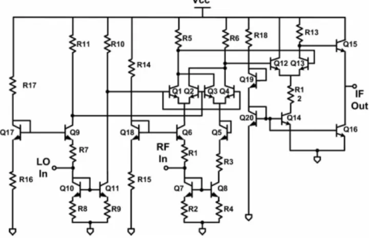
The mixer is a circuit with two high-speed ports and one low-speed port. The speed of the RF input port in a down-conversion mixer must be fast enough to response the RF input signal. Thus, the emitter degeneration and the micromixer topology are used to increase the input RF bandwidth of the mixer [1– 4]. A Gilbert mixer needs balanced IF, LO, and RF signals for higher conversion gain, better dynamic range, and good isolation [5]. The RF stage of micromixer can generate truly balanced RF signal and increase the Figure 1 The circuit schematics of single-ended GaInP/GaAs HBT micromixers with an LO active balun
Figure 2 The die photo of the micromixer using the active LO balun
RF bandwidth simultaneously. On the contrary, the speed of the mixer Gilbert cell is usually faster than that of the RF stage, and the challenge of the LO stage is to supply a pair of truly differential LO signals.
A micromixer using LO on-chip baluns is demonstrated in this paper. The RF, LO, and IF ports of the micromixer are single-ended; therefore, they are suitable for the stand-along board-level applications. A micromixer with an LO active balun is demon-strated as shown in Figure 1. Generally speaking, the active balun has advantages in terms of the smaller chip area by the active balun when compared with the passive baluns [6, 7]. A new experimental observation method is developed in this paper to indicate the LO signal balance. The maximum port-to-port isolation occurs when the LO and RF signals are truly differential.
The best LO-to-IF and LO-to-RF isolations can be achieved when the LO signal is truly balanced. Thus, the observation on the port-to-port isolations can effectively indicate the LO signal bal-ance. In this paper, the mixer using the active balun keeps the same when varying the frequency of the LO signal. It is because the active balun has a wideband response. The mixer using the active balun has 12 dB gain and smaller chip area. The RF-to-IF,
LO-to-IF, and the LO-to-RF isolations of the mixer with the active balun are about⫺5, ⫺20, and ⫺30 dB, respectively.
2. CIRCUIT DESIGN
The down-conversion mixer in Figure 1 consists of a LO Gilbert mixer core (Q1, Q2, Q3, and Q4) with an on-chip LO balun (Q9 to Q11, and R17 to R10), an active RF single-to-differential transconductance stage (Q5, Q6, Q7, and Q8), and an IF output differential amplifier (Q12 and Q13) with a common-collector output buffer, Q15.
The Gilbert mixer with the RF input stage in Figure 1 is known as the micromixer. The single-to-differential transconductor re-places the conventional emitter-coupled-pair transconductor in the Gilbert down-conversion mixer and does not consume extra power [1, 2]. The diode-connected transistor Q7 lowers the impedance of the common-emitter transistor Q8 and thus improves the frequency response of the RF input port.
The active balun requires extra biasing current and the dynamic range is usually worse than that of the passive lumped rat-race hybrid [6, 7]. However, the active balun consumes only very small chip area and provides some gain for the LO signal. Figure 2 Figure 3 The measured LO-to-IF and LO-to-RF isolations of the GaInP/
GaAs HBT micromixer with the active balun
Figure 4 The measured RF-to-IF isolation of the GaInP/GaAs HBT micromixer with the active balun
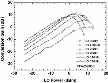
Figure 5 The measured conversion gain as a function of the LO power of the micromixer with the active balun
Figure 6 The measured IP1dBand IIP3of the GaInP/GaAs HBT
micro-mixer with the active balun
shows the die photo of the micromixer using active LO balun. This all single-in and single-out mixer consumes very small IC area of 350⫻ 200m2including the active balun. The micromixer with
passive balun consumes biasing current of 20 mA, whereas the current consumption of the mixer with active balun is 25.4 mA. The DC supply voltages of both mixers are 4.5 V.
3. EXPERIMENTAL RESULTS
Figure 3 shows the LO-to-IF and LO-to-RF isolations of the mixer using the active balun. The LO-to-IF isolation and the LO-to-RF isolation are better than⫺20 and ⫺30 dB, respectively. Because the active LO balun has broadband frequency response, the mea-sured port-to-port isolations do not vary significantly as the LO frequency sweeps. Figure 4 shows the RF-to-IF isolation and it is better than⫺5 dBm.
In general, the BJT-type Gilbert cell requires only small LO power; therefore, the conversion gain as a function of the LO power should have a flat response. It is because when the LO voltage is larger than 100 mV (four times of the thermal voltage, VT), the LO Gilbert cell begins to commutate the RF current as long as the LO signal is truly differential. Figure 5 shows the conversion gain as a function of the LO power of the micromixer
using the active balun. When the LO frequency increases, the conversion gain degrades because the active balun has a low-pass frequency response.
Figure 6 shows the measured IP1dBand the IIP3of the mixer with the active balun when the RF frequency is 3.8 GHz and the LO frequency is 3.5 GHz. Under the LO power of 2 dBm, the IP1dBand IIP3are⫺9 and 1 dBm, respectively. Figure 7 shows the RF frequency response of the mixer using active balun. The RF bandwidth is about 9 GHz because of the micromixer input stage. Because of the micromixer, the response of the input stage is improved and is up to 9 GHz.
Figure 8 shows the input return loss of the micromixer using the active LO balun. The measured input S11, which is better than ⫺15 dB, shows that the micromixer has wideband input imped-ance matching. On the other hand, the output return loss is shown in Figure 9. The measured S22is better than⫺17 dB from 50 MHz to 3 GHz. The output stage of the demonstrated micromixer is a common collector stage, and thus the output impedance matching is also wideband. Figure 10 shows the measured IF bandwidth of the GaInP/GaAs HBT mixer.
Figure 7 The measured RF bandwidth of the GaInP/GaAs HBT mixer with the active LO balun
Figure 8 The measured input return loss of the GaInP/GaAs HBT mixer with the active LO balun
Figure 9 The measured output return loss of the GaInP/GaAs HBT mixer with the active LO balun
Figure 10 The measured IF bandwidth of the GaInP/GaAs HBT mixer with the active LO balun
3. DISCUSSIONS AND CONCLUSIONS
A Gilbert micromixer is demonstrated in this paper using GaInP/ GaAs HBT technology, and the stand-along micromixer is suitable for hybrid RF system applications. The fully matched and high-linearity micromixer has a conversion gain of 12 dB, IP1dBof⫺9 dBm, IIP3of 1 dBm when fIF(input)⫽ 300 MHz, fLO⫽ 3.5 GHz,
and fRF(output)⫽ 3.8 GHz. ACKNOWLEDGMENTS
This work is supported by the National Science Council of Taiwan, Republic of China, under contract numbers NSC 96-2752-E-009-001-PAE, NSC 95-2221-E-009-043-MY3; by the Ministry of Eco-nomic Affairs of Taiwan under contract number 95-EC-17-A-05-S1-020; MoE ATU Program under contract number 95W803; and by the National Chip Implementation Center (CIC).
REFERENCES
1. J. Durec and E. Main, A linear class AB single-ended to differential transconverter suitable for RF circuits, IEEE MTT-S Dig, San Fran-cisco, CA (1996), 1071-1074.
2. B. Gilbert, The MICROMIXER: A highly linear variant of the Gilbert mixer using a bisymmetric Class-AB input stage, IEEE J Solid-State Circuits 32 (1997), 1412-1423.
3. C. Meng, S.S. Lu, M.H. Chiang, and H.C. Chen, DC to 8 GHz 11 dB gain Gilbert micromixer using GaInP/GaAs HBT technology, Electron Lett 637-638.
4. C.Y. Wang, S.S. Lu, C. Meng, and Y.S. Lin, A SiGe micromixer for 2.4/5.2/5.7-GHz multiband WLAN applications, Microwave Opt Tech-nol Lett 41 (2004), 343-346.
5. K.W. Kobayashi, R.M. Desrosiers, A.G. Aitken, J.C. Cowles, B. Tang, L.T. Tran, T.R. Block, A.K. Oki, and D.C. Streit, A DC-20-GHz InP HBT balanced analog multiplier for high-data-rate direct-digital mod-ulation and fiber-optic receiver applications, IEEE Trans Microwave Theory Tech 48 (2000), 194-202.
6. S.J. Parisi, 180o lumped elements hybrid, IEEE MTT-S Dig 3 (1989), 1243-1246.
7. A.P. Freundorfer and C. Falt, A Ka-band GaInP/GaAs HBT double balanced upconvert mixer using lumped element balun, IEEE MTT-S Dig 2 (1996), 17-21.
© 2008 Wiley Periodicals, Inc.
A NOVEL RECONFIGURABLE
CIRCULAR POLARIZATION PATCH
ANTENNA
Jun Ouyang, Feng Yang, and Shiwen Yang
Department of Microwave Engineering, School of Electronic Engineering, University of Electronic Science and Technology of China (UESTC), Chengdu 610054, People’s Republic of China; Corresponding author: antenna_ou@.163.com
Received 28 November 2007
ABSTRACT: A novel design of a microstrip patch antenna with
switch-able branches is proposed to achieve circular polarization diversity. Two branches are incorporated into the patch and two switches are uti-lized to switch the branches on and off. By turning the switches on or off, this antenna can radiate with either right-handed circular polariza-tion or left-handed circular polarizapolariza-tion using the same feeding probe. Experimental results validate this concept. This design demonstrates useful features for wireless communication applications and future planetary missions. © 2008 Wiley Periodicals, Inc. Microwave Opt
Technol Lett 50: 1921–1923, 2008; Published online in Wiley Inter-Science (www.interscience.wiley.com). DOI 10.1002/mop.23537
Key words: diversity method; microstrip antennas; polarization 1. INTRODUCTION
Antenna systems that utilize polarization diversity are gaining popularity because of the development of wireless communication in recent years. Polarization diversity antennas provide a powerful modulation scheme [1]. In [2] and [3], a reconfigurable antenna was built from a dual-polarized aperture-coupled antenna, which used a 3-dB hybrid branch-line coupler as a polarizer to obtain circular polarization (CP). Boti et al. [1] proposed a compact single-feed switchable antenna with four-beam lead pin diodes inserted directly on coupling slots, but with three metallization levels. To switch the polarization sense, Yang and Rahmat-Samii [4] used only two diodes directly mounted on two orthogonal slots incorporated on the probe-fed patch antenna. In [5], the switching between right-handed circular polarization (RHCP) and left-handed circular polarization (LHCP) is obtained by turning ON/ OFF two pairs of beam-lead pin diodes soldered near an annular slot ring. With the same radiating structure, Ho et al. [6] used two pin diodes on a uniplanar antenna where both the radiating element and feed-line circuit were on the same layer. In a recent project to build a Mars rover, a patch antenna with dual-frequency and dual-polarization capabilities is required [7]. In light of these applications, we present a novel antenna for polarization diversity: a patch antenna with switchable branches that can achieve RHCP and LHCP with a single feeding port. The patch antenna is selected because of the desirable features it possesses, such as low profile, light weight, and conformability with RF circuitry. Two branches are incorporated into the square patch and two switches are posi-tioned to control their status. By turning the switches on or off, either RHCP or LHCP be obtained with the same feeding probe which is located on the diagonal line of the patch. Compared with previous designs, this antenna is simple and attractive in that it involves only one patch and a single feed. It is also worthwhile to point out that the RHCP and LHCP are time separated so that there is no coupling between these two polarizations. The validity of this concept is demonstrated by experimental results with good axial ratios (ARs) achieved in both RHCP and LHCP operations.
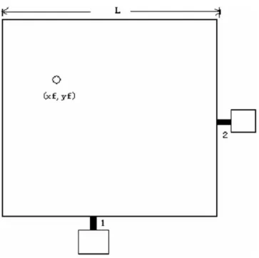
Figure 1 Geometry of a patch antenna with switchable branches for RHCP/LHCP diversity