PLEASE SCROLL DOWN FOR ARTICLE
This article was downloaded by: [National Taiwan University] On: 22 December 2008
Access details: Access Details: [subscription number 905688744] Publisher Taylor & Francis
Informa Ltd Registered in England and Wales Registered Number: 1072954 Registered office: Mortimer House, 37-41 Mortimer Street, London W1T 3JH, UK
International Journal of Computational Fluid Dynamics
Publication details, including instructions for authors and subscription information: http://www.informaworld.com/smpp/title~content=t713455064
SEPARATED FLOW ABOUT A TWO-DIMENSIONAL ELLIPSE IN
LONGITUDINAL OSCILLATION: FORCES AND VORTEX STRUCTURES
Chien-Cheng Chang a; Ruey-Ling Chern a
a Institute of Applied Mechanics, College of Engineering, National Taiwan University, Taipei 10764, Taiwan, R.O.C
Online Publication Date: 01 January 1993
To cite this Article Chang, Chien-Cheng and Chern, Ruey-Ling(1993)'SEPARATED FLOW ABOUT A TWO-DIMENSIONAL ELLIPSE IN LONGITUDINAL OSCILLATION: FORCES AND VORTEX STRUCTURES',International Journal of Computational Fluid
Dynamics,1:4,275 — 303
To link to this Article: DOI: 10.1080/10618569308904476 URL: http://dx.doi.org/10.1080/10618569308904476
Full terms and conditions of use: http://www.informaworld.com/terms-and-conditions-of-access.pdf
This article may be used for research, teaching and private study purposes. Any substantial or systematic reproduction, re-distribution, re-selling, loan or sub-licensing, systematic supply or distribution in any form to anyone is expressly forbidden.
The publisher does not give any warranty express or implied or make any representation that the contents will be complete or accurate or up to date. The accuracy of any instructions, formulae and drug doses should be independently verified with primary sources. The publisher shall not be liable for any loss, actions, claims, proceedings, demand or costs or damages whatsoever or howsoever caused arising directly or indirectly in connection with or arising out of the use of this material.
Camp. FluidDyn., 1993, Vol. 1, p. 275-303 Reprints available directly from the publisher Photocopying permitted by license only
© 1993 Gordon and Breach Science Publishers, S.A. Printed in the United States of America
SEPARATE]) :FL()W ABOUT A TWO-DIMENSIONAL
ELLIPSE: IN I.JONGITUDINAL OSCILLATION:
FORCES
A~rDVORTEX STRUCTURES
CHIEN-CHENG CHANG and
RUEY-LING CHERN
Institute of Applied Mechanics, College of Engineering, National Taiwan University, Taipei 10764, Taiwan, R.O.C.
(Received 15November1992;Revised26February 1993) SUMMARY
Numerical analysis by a hybrid vortex method is carried out for the flow around a two-dimensional ellipse in harmonic translation at the 30°-angle relative to an oncoming stream. The Reynolds number considered is focused on 1000 and the axis ratio of the ellipse is chosen to be 8:1.The reduced amplitude Aof the harmonic translation ranges from 0.4 to 1.8, while the reduced frequency kranges from 0.1 to 0.7. The paper aims at analysing how the vortices in the wake contribute to the force and moment coefficients through the vorticity generated around the leading and trailing edges. Lift, drag and moment elements related to corresponding potential flows and the cross product of the velocity and vorticity are proposed for this purpose. Furthermore, it is shown that for a givenAthe total lift coefficient averaged over a period of motion attains a maximum at Ak "'"0.43; the maximum lift coefficient increases with increasingA.Near-wake flow patterns such as streamlines and vorticity structures concerning dynamic stall and vortex lift enhancement will be identified according to when a maximum or a minimum of the vortex lift coefficient is attained.
1. INTRODUCTION
Research effort on unsteady airfoils has been intensified during past several years. The present study concerns numerical study of flow around a two-dimensional ellipse in harmonic translation at an angle to a uniform oncoming stream. The
situation has been considered ideally two-dimensional modelling of much
complicated practical problems, e.g., the flow past the rotor of a helicopter and a highly manoeuverable aircraft in forward acceleration and deceleration. Basic features such as lift enhancement, the phenomenon of vortex shedding, and characteristics of dynamic stall are the points of primary interest. The paper aims at analysing these features from the viewpoint of vorticity with specific emphasis on the effects of vorticity generated around the leading and trailing edges of the ellipse during a period of motion. Numerical method for the purpose is a modification of the hybrid vortex method developed previously by the authors for
flow around a circular cylinder; see Chang (1989) and Chang & Chern (1991).
275
276 C.-C. CHANG A N D R.-L. CHERN
The ellipse is set t o be at the angle of attack of 30" relative t o a uniform oncoming stream. In order not t o be complicated by turbulence, the Reynolds number Re = 2cUlv of the present study will be focused on 1000 with 2c the focal length, v the kinematic viscosity and U the velocity of the oncoming stream. In a few cases, the results for the lift coefficient will be checked against the angle of attack (20' $ a $ 40') and the Reynolds number (500 $ Re $ 3000). In their study o f flow around rectangles, Davis & Moore (1982) have noted that the characteristics of unsteadiness can be adequately studied through flow a t relatively low Reynolds numbers. Besides Re, two important physical parameters involved are the reduced
amplitude X and the reduced frequency
i .
The range of X = 2nfAlU is from 0.4 t o 1.8 whilek
= k / 2 a (k = 2nfclU) ranges from 0.1 t o 0.7 where A and f are respectively the amplitude and frequency of oscillation of the ellipse. The ranges for the values of X andi
of the present study are substantially wide; this enables us to obtain the condition under which the lift averaged over a period may attain a maximum for given reduced amplitudeA.
T o the authors' knowledge, relatively few numerical works have been devoted t o the study of flow around an airfoil in harmonic translation. General reviews about two- and three-dimensional lifting surfaces are available; some useful references are McCroskey (1982), Ericsson & Reding (1987) and Lee & H o (1990). Of direct interest to the current study are Maresca, Favier & Rebont (1979) and Gursul& H o (I 990) who respectively examined experimentally an airfoil in harmonic translation and in a periodic oncoming stream. The Reynolds numbers in these studies are in a range near lo5, which is much higher than 1000 of the present study. The primary interest of these studies is t o relate lift coefficients t o global flow behaviours. Owing t o the limitation of instrumentation, these authors usually restricted themselves t o relatively small values of reduced amplitudes and frequencies. Moreover, information about vorticity is difficult t o obtain from experimental works; it is thus helpful t o appeal t o numerical analysis in this respect since flow with large separation is generally considered being vorticity-dominated. As regards t o the elliptic geometry, Lugt & Haussling (1974) and Patel (1981) investigated the flow around a stationary elliptic cylinder. Recently, Ohmi et al. (1990, 1991) carried out
jointly an experimental and numerical analysis of flow around an ellipse in pitching motion. The Reynolds numbers in these studies are in the range from 100 t o 10 000. Numerical results of the present study will be compared to asymptotic results at small times and t o those of Lust & Haussling (1974) a t relatively long times t o ensure the accuracy of the present results.
Concerning the lift, Kasper has suggested t o enhance the lift by leading-edge vortices (cf. Kruppa 1977). Saffman & Sheffield (1977) investigated inviscid flow over a wing with a free line vortex standing over the wing and confirmed that the lift on the wing can be much increased by the vortex. During manaeuvre, leading- edge vortices are generated effectively by unsteady motion of the airfoil and usually cannot stay o n the wing and will be shed. It is therefore important t o understand how the vortex shedding, o r more precisely vorticity shedding, is connected t o the manoeuvering conditions of the airfoil. For example, Walker, Helin & Strickland (1985) examined an airfoil undergoing large-amplitude pitching motion and found that the higher the value of pitching rate, the more energetic the leading-edge vortex
SEPARATED FLOW 277
and the higher the reverse flow velocities near the surface of the airfoil. Since the airfoil is in unsteady motion, we separate the lift t o a part due t o acceleration-called the added-mass lift, and a part due t o the vorticity-called the vortex lift. We shall identify under various A and
R
the flow patterns according t o when a maximum or a minimum vortex lift coefficient is attained. T o relate the lift coefficients t o the observed flow patterns, we propose t o investigate the distribution of 'lift elements' which enable us t o assess how an individual vortex in the flow contributes t o the vortex lift through the vorticity. Similar analysis applies t o the drag force and the moment about the centre of the airfoil. Furthermore, time variation of the total enstrophy is employed t o explain the time history of the lift coefficient. Mutual relations between vortex shedding, dynamic stall and the lift enhancement will be examined with the plots of streamlines, contours of vorticity and lift elements.2. BASIC EQUATIONS
Consider a fluid of constant density p and constant kinematic viscosity v . The flow past the ellipse is assumed t o be governed by the Navier-Stokes and the continuity equations. Consider the frame moving with the translating velocity ( - U ) of the
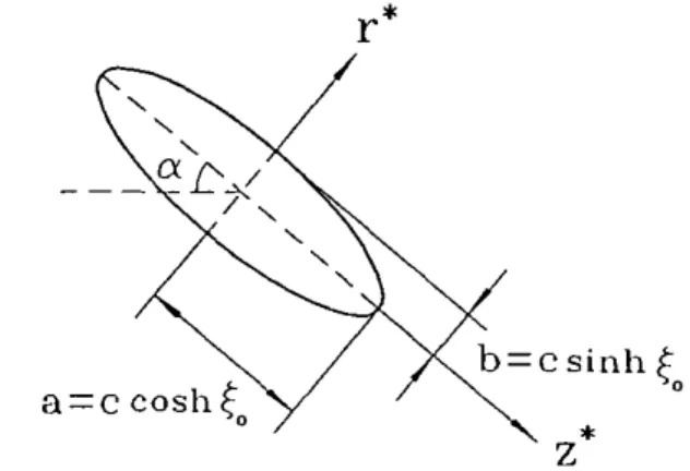
ellipse. Some flow parameters are shown in Figure 1. Let the reference length and velocity be respectively one half of the focal length ( c ) and the maximum speed of the distant flow ( U ) . In dimensionless form, these equations may be written
where u denotes the velocity and P denotes the pressure. The Reynolds number is defined t o be Re = 2Uclv; sometimes it is convenient to use Red = 2Ualv with 2 0 the chord length of the ellipse. The dimensional velocity u * , time t * and pressure
Figure 1 Schematic of the physical problem
278
P* are given by
C:C. CHANG AND R.-L. CHERN
The equations of motion are conveniently written in terms of the elliptic coordinate system ( t , 0) which is defined by
x*
+
iy* = c cosh(F + i0). (4)The contour of the ellipse is represented by the constant coordinate line (surface)
[ = £0. The focal length is 2c while the chord length is 2 a = 2c cosh £0. The ratio
o f the major axis t o the minor axis is given by R = coth €0 = l/tanh
to.
For the present study, we shall also need t o use the equations of motion based on the stream function-vorticity formulation. Let $ be the stream function and denote the vorticity by w(wk) = V x u. We have
where h 2 = cosh2 [ - cos2 0 and
v2
= h-2(aZ+ a:). The velocity components ur and us are related to $ throughAt the surface o f the ellipse, the boundary conditions can be chosen t o be
Far away from the ellipse, the flow is a uniform parallel flow; the appropriate far field condition is given by
where U(t) is the relative speed of the distant flow t o the ellipse in longitudinal oscillation. Equations (5) and (6) subject t o (8) and (9) will be solved by a deterministic hybrid vortex method. Two physical parameters characterizing the oscillation of the ellipse are the reduced amplitude A = 2 ~ f A l U and the reduced frequency k = 27r fc/U vhere A and f are respectively the amplitude (measured in distance) and the frequency of the oscillation. In terms of A and k, f and the
SEPARATED FLOW 279
incoming speed
U,
we haveFor convenience, we define k = k/2n, and shall also call k the reduced frequency.
3. T H E HYBRID VORTEX METHOD
The present vortex method can be abbreviated as follows. The vorticity field is approximated by a sum of 'blob' functions - called vortex blobs or simply vortices. Each vortex evolves in a Lagrangian manner, carrying with itself a circulation determined from the vorticity. The vorticity is obtained by solving the vorticity diffusion equation on a grid by finite difference. The circulations are then redistributed and converted back to the vorticity on the grid, which is thus updated. At the beginning of each time step there are only vortices centred at mesh points. First of all, we approximate the vorticity field by
L
w ( t , x ) =
C
r j
f,(x - x,)j = 1
where L denotes the number of vortices (or mesh points) and f j (x) is the blob function. rj (in the absolute frame) and x, are respectively the circulation and
position associated with the jth vortex blob. In practice, the function fj(x) is conveniently taken to be an indicator function so that the vorticity is constant over the underlined indicator set outside which the blob function is zero.
Next we introduce the numerical grid for the solution of equation (5) and for the creation of vorticity along the ellipse surface. The grid is also used to solve the vorticity diffusion equation in order to take into account the effect of viscous diffusion. In terms of the coordinates
(E',
0) the equation (5) may be writtenwhere
280 C . - C . CHANG AND R.-L. CHERN
For each time increment, equation (12) is solved on a mesh with a uniform mesh size in the coordinate system (E', O), defined over an annular region (1
<
<
&). Fine resolution is required near t o the surface of the ellipse. The constants A , Bin (13a) are fixed by the radial mesh spacing at the ellipse surface, and by the value of the outer surface at
ER.
The value ofER
must be sufficiently large for (1 1) to be an adequate approximation and for all the vortices t o be contained within the mesh. Denote by ( i , j ) the node o f the mesh;E'
= j and O = i A0 (A0 = nip, 0 b j<
q - I). Let $(i, j ) be the nodal value of the stream function at (i, j ) . Equation (12) is solved by central finite difference in [' with the help of Fourier collocation for the second derivative in 8 . This yields a set of p tridiagonal equations in .$', which can be solved efficiently by Gaussian elimination. Once equation (12) is solved, the stream function is used t o update the vorticity o n the ellipse surface so that the no-slip condition is satisfied. Notice that along the ellipse surface, equation (12) reduces t oImagine that the stream function can be extended across the ellipse surface to possess meaningful values $(i, -1). Then at least to the first order approximation, we require $(i, -1) = $ ( i , 1) so that the tangential velocity along the ellipse surface is zero. Applying the central finite difference to equation (14) yields then the surface vorticity
The value of w(i,O) in (15) can be evaluated accurately by interpolating the stream function using three or more radial mesh values near t o the surface of the ellipse, followed by differentiation. With the solution of (12) and the surface vorticity w(i, 0) in (IS), the next step is t o solve the diffusion equation o n the grid by a finite difference method,
From the solution we form the circulations to be convected by the vortices o n the grid. Let Aij be the cell determined by (i - 112, j ) , (i
+
112, j ) , (i, j-
112) and (i, j + 112). Each Aij corresponds t o an indicator set in the original x-space. The circulation associated with the vortex at (i, j ) is then determined approximately byThe formula is obtained by applying the midpoint rule for evaluating, in the ( [ I , 8) plane, the integral of the vorticity over the area corresponding t o A i j . The vortex
SEPARATED FLOW 28 1
carrying r ( i , j ) is convected to a new location with the velocity determined from the formula (7). The circulation r ( i , j ) is then redistributed between the four corner nodes of the cell in which the vortex is contained according to the area weighting scheme (cf. Chang and Chern 1991). The redistribution of circulations completes a cycle of computation; recall that the conversion of circulation into vorticity, and vice versa, is made through the formula (17). The last step updates the vorticity on the grid. The present vortex method therefore, for each time increment, consists of the following solution steps.
(i) Equation (12) for the stream function is solved on the grid; the solution is used t o update the vorticity along the ellipse surface to satisfy the no-slip condition; (ii) equation (16) is solved on the grid by a finite difference; the circulation associated with each vortex on the grid is then evaluated according to the formula (17);
(iii) each vortex on the grid together with the associated circulation is convected with the velocity determined by (7) using the values of the stream function obtained in (i);
(iv) redistribute all the circulations; add at each mesh point the contributed circulations and convert the result into vorticity, again, according t o the formula (17).
The method described above is of fractional-step type. The time accuracy can be improved by adopting a midpoint rule for evaluating the velocities of the vortices on the grid. One way of achieving this is to calculate the velocities using the average of the current vorticity and a predicted vorticity at the next time step. This modified procedure is conceived to have second order accuracy in time, and which is actually used in computation in the present study. It is noticed that the area-weighting scheme which locally smooths the vorticity field is indeed a mild source of numerical diffusion, even though the effect of which becomes smaller as the meshing is finer. For more details about the hybrid vortex method, we refer to Chang & Chern (1991).
4. FORCE A N D MOMENT COEFFICIENTS
In this section, we consider different formulas for evaluating the lift, drag and moment coefficients and propose a decomposition for these coefficients.
Let D*, L * and M* denote the total drag, lift and moment exerted by the fluid on the ellipse per unit span. The drag, lift and moment coefficients are defined by
282 C.-C. CHANG AND R.-L. CHERN
Pressure and friction. Each of the coefficients consists of two parts: one due t o pressure and the other due t o friction, i.e., CD = CDP
+
CDF, CL = CLP+
CLF, CM = CMP+ CMF. Let So denote the surface of the ellipse of unit span. The dimensionless force and moment are given bywhere n is the unit vector directed inward the ellipse. The unit vectors i and j are along the major axis and minor axis respectively. Projections of (19) along the a-direction and its orthogonal normal in the counterclockwise sense respectively give
CD = (cos a
-
C,+
sin a . C2)lcosh €0, (2 1 a) CL = (-sin a . C I+
cos a-
C2)/cosh €0, (21b) while C3 is related t o the moment coefficient CM through CM = C ~ / C O S ~ ' £0. Theforce and moment coefficients can be easily expressed in terms of the vorticity and its normal derivative on the surface of the ellipse. Employing the elliptic coordinates, we have
C , =
$
1:'
(lanh ( - sin 6' dB. cosh&
-i
n u sinh 2(0 cos a , (22a).cos 6' dO.cosh €0 - ; n u sinh 2(0 sin a.
For the surface integrals, the terms involving the derivative of the vorticity are due t o pressure, otherwise the terms are due t o friction. It is also noticed that the inertial forces appear with minus sign, since for the moving frame, the surface integrals include both the effects of induced-mass and inertial forces; the latter should not appear in the case of accelerating the ellipse but not the distant fluid.
The moment coefficient is given by
Though these formulas are simple in their forms, the derivative terms are not satisfactory for the numerical purpose. For the pressure contribution, we shall, instead, evaluate for each azimuthal angle the surface pressure. Rewrite equation
SEPARATED FLOW 283 (1) in the form:
d u a u 2
- v p = - + - + ( u . V ) u + - v x o .
d t a t Re
Taking the &components on both sides gives
Prescribed t o be 0 at infinity, the pressure P = P(E, 8 ) will be obtained, for each 8 , by integrating the momentum equation radially from infinity t o the position
(E,
8 ) . Another decomposition. The force and moment coefficients may also be written in terms of integrals without involving the derivative of the vorticity on the surface. We shall derive a set of formulas along the lines of Quartapelle & Napolitano ( 1 9 8 3 ) .Let q = q ( x ) be a harmonic function defined in the flow region in V, and assume that q decays rapidly away from the ellipse. Taking inner products o n both sides of equation ( 2 4 ) with Vq and integrating the resultant expression over the region V R which is enclosed by S = SO U SR ( S R : a large surface) yield
where we have used the two identities u - Vq = V . ( u q ) and (V x o ) . V q = V . ( o x V q ) . Recall the identity u . Vu = v u 2 / 2 - u x o. The second term on the right hand side of ( 2 6 ) can be further rewritten
1
( u . V u ) . V q d V = u' V q . n d A -
[
u x o . V q dV.VR 2 s VR
( 2 7 ) Define three harmonic functions 71,112 and q 3 such that they satisfy, on the surface of the ellipse,
It is reminded that qi (i = 1 , 2 , 3 ) are assumed t o decay rapidly t o 0 at infinity in the present study. From all the conditions required for q1 ( q z ) , we see that q ~ (112) has the physical meaning of being the potential function due to the body moving in the negative of direction i ( j ) with unit velocity.
The introduction of ? I , qz and 9 3 enables us to express the contributions from
the pressure t o the force and moment in terms of the kinematic quantities u and
284 C.-C. CHANG AND R:L. CHERN
w rather t i a n their derivatives. The identities (26), (27) and (28) consist of the basic formulas for determining forces and moment in this approach. Three harmonic functions satisfying the conditions in (28) are
These functions are rapidly decaying t o zero as [ tends t o infinity. With q = ? I , it is not difficult t o see by a simple calculation that (26) becomes, as R -+ a,
where we have added the contribution from the friction. The first term on the right hand side of (30a) is solely due t o the potential flow induced by the unsteady motion of the ellipse (added-mass force). Here, we note that the first integral on the right hand side of (27) does not have contribution in deriving (30a). Concerning the left hand side of (26), the integral over SR is equal to 0 as R
-
oo since the pressure P is constant there.Similarly, with q = qz, we have that (26) becomes, as R
-
m,(30b) Similarly, for q = 73, we have
Formulas (30) and (31) reveal clearly that the only source for the drag, lift and moment for the viscous flow is the vorticity (besides the acceleration of the ellipse). Each of these formulas consists of two parts: one is in terms of an integral over the volume, the other is in terms of an integral over the surface; that is, we may write
Notice that the pressure contributes t o each of these coefficients while the friction contributes only t o Cis and C ~ S . Corresponding to CI, CZ, it is adequate t o define
For the sake o f clarity, we express El and Ez in elliptic coordinates,
,
El (x) = ~ e - ' ~ - " ' ( u e cos 0-
ut sin B).sinhto,
(34a)SEPARATED FLOW 285
Similarly, we may define SI (x) and S2(x) such that
In view of (31) and (32)-(35), we may also define
where CDA = ?ru(sinh2 €0
+
sin2 a)/cosh €0 and CLA = K U cos a sin alcosh € 0 . It isuseful t o write C L W = C L V + CLS which will be called the vortex lifr coefficient. Likewise, we may define Cow and CMW - the vortex drag and vortex moment coefficients. Hereafter, the integrands of CDV and C L Y - denoted by D,(x) and
Le(x) - will be called the volume drag and volume lift elements respectively. For later use, it is helpful t o write Le more explicitly,
The element of the moment coefficient M,(x) can be defined similarly. It is seen that it is the triple products u x o
.
Vq; ( i = 1 , 2 , 3 ) that determines the local contribution interior t o the fluid. The product is invariant under the reversal of the velocity field because then the vorticity field changes its sign likewise. Of particular interest is t o note here that the following relations hold,C I S = (tanh €0
+
~ ) C I F . CZS = (coth $0+
I)CZF. (38)The proportional constants g l = tanh €0
+
1 and g2 = cothto
+
1 which arerespectively equal t o 1 / R
+
1 and R+
1 (R: axis ratio) may be termed the geometric factors since they are determined by the shape of the ellipse. The geometric factor gl has the least upper bound 2 for the limiting case of a circular cylinder, while g2 has exactly the same number 2 as its greatest lower bound. Since the factors g; - 1( i = 1,2) indicate the effects of the pressure, we see that for a slender ellipse, the pressure has negligible contribution t o CIS whilst reinforcing the contribution through the surface vorticity t o Czs. Actually, from (21), (32), (36) and (38), we have
CDS = (1
+
I/R)CDF+ sin a ( R - l / R ) C z ~ / c o ~ h € 0 , (39a)Typically, all the friction coefficients are quite small; the results of (39), however, tell us that the coefficients CDS and CLS may not be negligible even when CDF and CLF are small. This is because the contribution of CZF t o CDS and CLS must be multiplied by R - I / R which is large for a slender ellipse. It is interesting to see that
either CDS or CLS could have a large contribution from CZF (along the minor axis) rather than C I F (along the major axis). For each of the formulae, the second term on the right hand side signifies the contribution from the pressure.
286 C.-C. CHANG A N D R.-L. CHERN
5. RESULTS A N D DISCUSSION
Numerical results are mainly presented for Re = 1000, a = 30' a t various A and
R.
In a few cases, the flow behaviours will be checked against the Reynolds numberRe and the angle of attack a . The axis ratio of the ellipse is chosen t o be 8: 1. For
the grid, the inner radial spacing is taken t o be the standard deviation of diffusion over one time step; the outer numerical boundary is set at cosh [ = 37. The time step is 0.005 while the grid size is taken t o be 200 x 128 in the radial and azimuthal directions respectively. As a check of validity, we compare the computed lift, drag and moment coefficients t o asymptotic results and t o those obtained by Lugt &
Haussling (1974) for the stationary ellipse a t Re = 200, a = 45'. Let ho(0) denote h evaluated at
to.
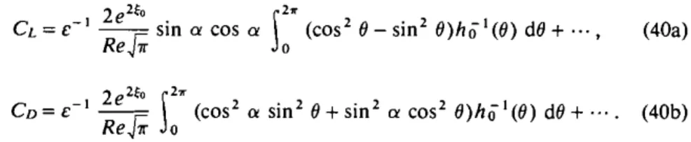
The asymptotic results for the lift and drag coefficients are obtained along the lines of Wang (1967) and Peace & Riley (1983) at small times, and are respectively given by2*
CL = c-I sin a cos a
1
(cos2 19 - sin2 e ) h i l ( e ) dB+
...
,
(4Oa)Re& o
Figure 2 shows the results of comparison. The present results are in close comparison with the asymptotic results in an initial portion of time. Moreover, the results show also close agreement with Lugt & Haussling's compared t o Patel's results (not shown here) which are in great discrepancy with Lugt & Haussling's. Below the results are all referred, unless stated explicitly, t o Re = 1000 and a = 30". All the calculations are performed o n a CraylXMP; each time step takes about 0.6 C P U second.
5 . I . Preliminary Observation
Consider a typical motion of the ellipse: X = 0.8 and = 0.25. The motion of the ellipse can be divided into four stages during a period: forward deceleration (FD), backward deceleration (BD), backward acceleration (BA) and forward acceleration (FA). Figure 3 shows a typical plot of the lift coefficient in the decomposition: CL = CU
+
CLW, CLW = CLY+
CLS for which CLP is also presented. It is observed that the lift coefficient CL reaches a maximum soon after the flow is started; the maximum is clearly due to the vortex lift (CLW) since at this time C u is negative. Generally, we see that the lift coefficient CL decreases rapidly (stall) during the stages F D & BD (deceleration) and increases rapidly (lift enhancement) during BA& FA (acceleration). Since the variation of CLA is known for a given motion of the ellipse, we therefore restrict ourselves t o the discussion of the vortex lift coefficient CLW in most cases of consideration. Roughly, one may think that the variation of the lift coefficient can be ascribed t o the variation of a n 'effective' Reynolds number
SEPARATED FLOW
Time
Time
Figure 2 Comparisons between asymptotic and numerical results: ---, asymptotic; -, present study,
.
., Lugt & Haussling (1974) ( R e = 200, a = 45' without oscillating the ellipse).C:C. CHANG A N D R.-L. CHERN
0 4. 8 12 I6 20
Time
Figure 3 Lift coefficients in the decomposition CL = CLW+ C u , CLW' CLY + CLS: -, CL; ---, CLW;
.
. ., C u ; -.
-.
CLS; - . . - , CLF ( A = 0.8. k = 0.25).which is measured by the relative speed of the ellipse t o that of the distant flow. However, this is not sufficient t o explain the detailed nature of the variation of the vortex lift coefficient CLW with the flow structures from the point of view of vorticity, though the contribution from the potential flow CU is known for a given motion of the ellipse. The detailed nature consists of the main subject t o be pursued further below, and one'problem of particular interest concerning the vortex lift coefficient can be addressed as follows. During the backward motion, the ellipse becomes close t o the vortices previously generated around both of its edges, which may be thought of as being in a manner t o 'hold' the vortices on its back. Could such a situation lead t o high vortex lift? The answer is obviously 'no' from this preliminary observation. T o explain this behaviour requires indeed a detailed analysis of the flow structures, and our answer will be brought out at the end of 55.4.
5.2. Lift Elements and Enstrophy
A point of interest worthy of prior attention is t o see how the lift elements accumulate themselves t o yield the vortex lift. The purpose is t o integrate L,(x)
from the surface &I t o a fixed [ and then add the result t o the surface vortex lift
coefficient CLS, which is thus a function of the distance measured by cosh t/cosh
&,.
Figure 4 shows the results at t = 0.22, 2.08, 4.10, 6.12, 8.10 and 10.16, corresponding t o the initial maximum vortex lift and five successive minima and maxima for the case X = 0.8 and I? = 0.25. It is observed that the contribution fromthe lift elements is within about two diameters of the ellipse in all the cases. The curve for the initial high lift a t t = 0.22 tends t o be stationary within much shorter distance, while the successive extrema have major contributions from the lift elements within relatively long distances. It is therefore safe t o say that the lift elements are strong and concentrated near the surface.
Figure 4 Accumulation o f the lift elements: -, t = 0.22; ---, 2.08; . . . , 4.10; -
.
- , 6.12; -. .
-.
8.10; 1 0 . 1 6 ( X = 0 . 8 , k = 0 . 2 5 ) .
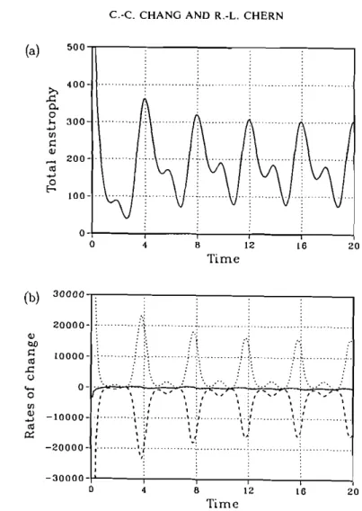
Since the vorticity is the 'source' of all the physical quantities and phenomena that we are interested in, it is helpful, at this moment, to ascertain the activity of the vorticity in the flow before detailed investigation of the flow structures. Perhaps, the most illuminating way of doing this is to examine the rate of change of the total enstrophy (Batchelor 1967, p. 271)
The first term on the right hand side is the rate of dissipation while the second term is the rate of production. Figure 5 shows each of these terms for the case X = 0.8,
= 0.25. First of all, it is interesting to see that except initially the total enstrophy varies periodically and does not increase with time though the rate of production is always positive. It is seen that the rate of dissipation may not be negligible during most of the time of a period. For each period, the total enstrophy attains two maxima: a major one and a minor one. The two types of maxima can be ascribed to strong activity of the vorticity of different signs. It is observed that the activity of the vorticity is typically weakest as regards to both of the rates of dissipation and production when the relative speed of the ellipse to the distant flow is minimum in magnitude. These rates are mild during the backward motion of the ellipse. Since the rate of dissipation is low, the vorticity within the flow has to be spread over widely during the backward motion (BD & BA) since otherwise strong gradients imply significant dissipation. On the contrary, the activity of the vorticity is relatively stronger during the phases of forward motion (FA & FD). Coherent vortices of intensive vorticity are expected to be largely generated around the leading and trailing edges, being accompanied by large dissipation near the surface of the ellipse. We see that a maximum vortex lift coefficient corresponds to a major
C:C. CHANG A N D R.-L. CHERN
o 4 a 1 2 20
T i m e
Figure 5 (a) Time variation of the total enstrophy, (b) -, rate o f change; ---, rate of dissipation;
....
rate o f production ( X = 0.8, f = 0.25). (b) 30000 20000- Q) w E: ,0000- m9
C 0 UI3
-lOOOO- m rx -20000- -30000-'maximum of the total enstrophy but not the maximum rate of production of vorticity. A major maximum of the total enstrophy corresponds t o the largest
effective Reynolds number, whiIe a minor maximum corresponds t o the smallest effective Reynolds number.
: ... ... + ;' ... r ... : ... : . ! . . ...
.
. . . . o ... : :: . > . , ..
.
. . . . . \ : i ..
... ..
... ....;...-
L.\ ;A.
. . . . . . . . :. . . . . . . . . . . . . . . . . . . . . . . . . ..
: . . . . . . . . . . . : . . . . . . . . . . . : : : . . : . . . : . . .... : . . . :.. .... : . , . . . . . . .7,
I , .I I.-.'
',-: . # '-\,'; I ,'--.#.',:
,---' , 9 ; , 0 : I I ' I : ' I :, ! i,',
:,.:
... :.+:....-...,.<
,
... I ( . :, , ...,
:' ., . . . k 1 v .,
: I 8 I I i :' I :I t <! 8,
' '2 ... ...;
$
... : ... : ... ; 15.3. Evolufion of Vorricity Structures
In this and the next sections, we shall study how the vortex lift CLW vary with the
flow structures. The problem will be first dealt with by numerical visualization of the vorticity distribution at various times. Consider again the case:
X
= 0.8,i
= 0.25.0 4 8 12 16 20
Time
SEPARATED FLOW 29 1
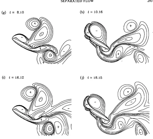
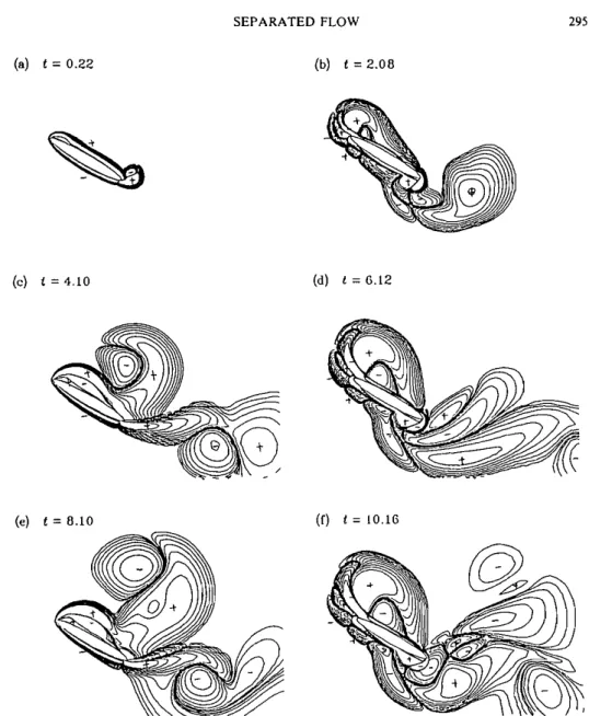
Figure 6(a-h) shows a sequence of plots of equivorticity lines at various times. Corresponding to the first maximum of the vortex lift at t = 0.22, Figure 6(a) indicates that a large contribution is due to a region of positive vorticity near the trailing edge, which consists of the starting vortex. Along the upper surface, there is a slender region of negative vorticity which will grow rapidly as the ellipse is being in forward deceleration (FD). The slender region is of highly concentrated vorticity, indicating that flow reattachment along the upper surface is likely. At t = 2.08, the vortex lift reaches its first minimum when the ellipse is in backward acceleration (BA), interacting with the vorticity in the lee'side of the ellipse. Figure 6(b) shows the formation of a tongue-shape region of positive vorticity o n the top of the leading edge, while the trailing edge intercepted the region of negative vorticity and cut it into two parts: one below and one above the trailing edge. The starting vortex has been shed and was displaced away from the ellipse by the region of vorticity near to the trailing edge. Figure 6(c) shows the plot at t = 3.09 which is in the half- way to the next maximum of the vortex lift and when the ellipse is about at its right- most position. Since from t = 2 to 3, the airfoil is still in backward motion, the
starting vortex, though having been shed, is not far away from the ellipse. A small protuberance of positive vorticity can be observed to form near the trailing edge. From t = 3 to 4, the ellipse is in forward acceleration (FA), substantial amount
of vorticity is expected to be generated around both of the leading and trailing edges. Figure 6(d) shows the plot of equivorticity lines at t = 4.10 when the vortex lift coefficient attains, again, a maximum. The small protuberance in Figure 6(c) has now grown into a large size which extends significantly downstream; all the previous regions of vorticity have been shed away from the ellipse. A region of newly generated vorticity forms along the upper surface; the situation is somewhat similar to that in Figure 6(a). Figure 6(e) shows the plot of equivorticity lines at
t = 5.1 1 (BD) which is an intermediate step leading to the next minimum of the vortex lift coefficient. The vorticity in the flow is seen to have been much diffused and convected downstream, and the different regions of vorticity are spread over the wake much widely. A protuberance of positive vorticity near the leading edge will eventually lead to a new tongue-shape region at the next minimum of the vortex lift coefficient. Figure 6(f) shows a close analogy with Figure 6(b) while Figure 6(g) shows a close analogy with Figure 6(d). Except the initial one - the starting vortex, these patterns appear repeatedly every period of the oscillation. Figure 6(h-j) shows additional plots of equivorticity lines for three extrema of the vortex lift coefficient at later times t = 10.16, 16.12 and 18.15.
From the above observations, we see that the patterns of the vorticity distribution can therefore be classified into five types: (I) the starting type (Figure 6(a)), (11) the type of maximum vortex lift (Figure 6(d,g,i)), (111) the type of minimum vortex lift (Figure 6(b,f,h, j), (IV) the intermediate type leading to a maximum vortex lift (Figure 6(c)) and (V) the intermediate type leading t o a minimum vortex lift (Figure 6(e)). The phases of motion associated with the stages F A and BD may be termed the phase of vortex lift enhancement and the dynamic-stall phase
respectively. Concerning the vorticity structures at other values of X and
i ,
we note that the patterns identified are representative of all the cases observed elsewhere.292 C:C. CHANG AND R.-L. CHERN
Tongue-shape regions observed during the phase of backward motion of the ellipse may have a smaller size a t lower values of
k,
and may curve towards upstream a t relatively larger values ofk.
Substantial amount of vorticity generated duringforward motion may even pass upstream through the leading and trailing edges when the ellipse is in backward motion a t relatively large
k.
(a) t = 0.22 (b) 1 = 2.00
( c ) t = 3.09
(c) t = 5 . 1 1
(d) t = 4.10
Figure 6 Vorticity distributions: (a) t =0.?2, (b) 2.08, (c) 3.09, (d) 4.10, (e) 3.11, ( f ) 6.12, (g) 8.10, (h) 10.16, (i) 16.12, ( j ) 18.15 (A=0.8, k=0.25; 0 = f0.1, f 0.2, 20.4. 20.8, f 1.6, 23.2).
SEPARATED FLOW 293
(g) t = 0.10 (h) t = 10.16
(i) t = 16.12 (j) t = 18.15
Figure 6 Continued.
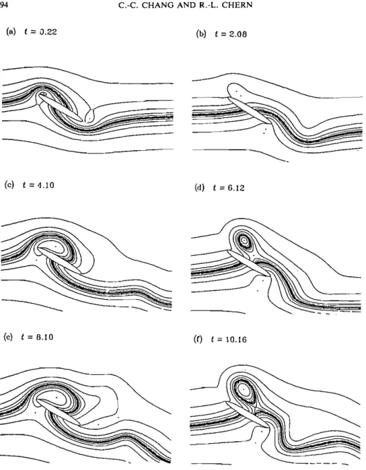
5.4. Streamlines and Vortex Lift Elements
Though the vorticity is invariant under translation of coordinates, it is also useful t o identify the streamline patterns and the distributions of the lift elements corresponding t o the starting type I and the types of maximum and minimum vortex lift. Again, consider the case X = 0.8,
k
= 0.25. Figures 7(a-f) and 8(a-f) present these plots in parallel. It is noted that the surface of the ellipse is not necessarily a streamline since the ellipse is in unsteady harmonic translation in the frame of reference.Before chasing each figure, let us examine some general connections between the patterns of lift elements and those of streamlines and vorticity. First, we see that a line dividing the lift elements of different signs may pass through the centre of a vortex (based on streamlines) since fluid elements near the centre form a closed loop: the vector u x
w'
makes a right angle twice with the smooth field Vvi (i = 1,2) as one goes around a loop enclosing the centre. Second, the lift element LC(%) could most possibly change its sign whenever the vorticity changes it sign. These partial294
(a) t = 3.22
C.-C. CHANG AND R:L. CHERN
(b) t = 2.08
Figure 7 Instantaneous streamline patterns: (a) r =P.22, (b) 2.08, ( c ) 4.10, (d) 6.12, (e) 8.10, ( f ) 10.16 ( A = 0.8, k = 0.25).
rules apply indeed if we look into the present plots of streamlines, vorticity and contours of lift elements.
Now we turn back t o the Figures 7 and 8. Figure 7(a) shows that the streamlines for the type I. A bubble of recirculation forms around the leading edge with a stagnation point existing in front of the ellipse, while curved streamlines emerge
SEPARATED FLOW
(a) t = 0.22 (b) t = 2.00
(c) t = 4.10 (d) L = 6.12
Figure 8 Conbtours of the lift elements: (a) 1 =0.22, (b) 2.08, ( c ) 4.10, (d) 6.12, ( e ) 8.10, (f) 10.16 (X=0.8, k=0.25; L,=?0.001, k0.002, k0.004, 20.008, 20.016, k0.032, 20.064, 20.128,
20.256, f 0.5 12, 2 1 .O24).
from the lower front surface and extend downstream. Concerning the lift elements, Figure 8(a) shows that type I has two substantial positive regions: one along the upper surface and another near to the trailing edge. The positive region of lift elements near t o the trailing edge is evidently due t o the starting vortex. Therefore we understand that as the starting vortex begins t o be shed at a later time, the vortex lift coefficient is henceforth decreasing rapidly.
296 C.-C. CHANG AND R.-L. CHERN
Figure 7(c,e) shows that type I1 bears a resemblance t o type I in the streamline patterns. Figure 8(c,e) shows that type 11 has a large positive and connected region of lift elements, which is a little far away from the upper surface and a positive region near to the trailing edge, extending significantly downstream. These two substantial regions of intensive lift elements have major contributions to the vortex lift coefficient. It is noticed that these regions are mainly due to the newly generated vorticity during the phase of forward acceleration (FA) of the ellipse, for all the previous regions of vorticity have been shed. It should therefore be understood that the process of vortex lift enhancement is not due to vortex shedding but is directly related to the generation of 'favourable' vortices of intensive vorticity. Vortex shedding (away from the ellipse) itself could most possibly cause a decrease of the vortex lift coefficient.
Figure 7(b,d,f) shows that type 111 has a vortex in the upper wake ending with a stagnation point, below which streamlines emerge from the upper surface, curving downward and extending downstream. Contrary to the clean patterns owned by I and 11, Figure 8(b,d,f) shows that the present type 111 has a quite complicated pattern of lift elements. The outstanding features of this type are a negative region near to the trailing edge and a negative region caused by the protuberance near to the leading edge. A large positive region of the lift elements is displaced away from the trailing edge; this corresponds to the similar displacement of the regions of positive vorticity (cf. Figure 6(b,f,h)). Since the ellipse interacts actively with the wake during the backward motion, complex regions of the lift elements also exist in front of the ellipse owing to the existence of substantial regions of vorticity of different signs there. This 'incoherent' complexity largely reduces the positive effect of the vorticity to the vortex lift, while the negative regions near to the ellipse leads to a negative vortex lift coefficient. The reorganization of the lift elements is no longer geometrically favourable of the vortex lift.
It may therefore be concluded that though it is true that a bulk of vorticity be close to the ellipse to acquire a high vortex lift, which is however not a sufficient condition since the lift element depends much o n Vq, ( I = 1,2) geometrically. Once
a vortex of intensive vorticity is generated, it will be followed immediately by a strong rate of dissipation, and once a vortex has been detached from the ellipse, it can no longer be reattached to the ellipse by any means. Coherent vortices of types I and I1 are indicative of high vortex lift coefficient. In other words, during manoeuvre, a high vortex lift can only be attained by generating attached vortices of intensive vorticity along the upper surface of the ellipse, not by interacting the ellipse itself with the previously generated vortices. Finally, it is remarked that as time increases the pattern of lift elements is getting complicated but the lift coefficient (cf. Figure 3) seems t o reach a periodic state (though not quite). This is
because only the lift elements near the ellipse contribute significantly to the lift coefficient (cf. Figure 4), while a close look reveals indeed nearly periodic structures of lift elements near the ellipse.
5.5. Surface Pressure and Pressure Con fours
The variation of the surface pressure in connection with the flow structures is now discussed. Consider again the case X = 0.8,
L
= 0.25. Figure 9 shows the plots of theSEPARATED FLOW
Figure 9 Surface pressure distributions: -, r = 0.22; ---.-2.08;
. . .
, 4.10; -.
-.
6.12; - . . - , 8.10; , 10.16 ( A = 0.8, k = 0.25).surface pressure at various times corresponding to the types 1-111 identified above, while Figure IO(a-f) presents the spatial pressure contours. For these types of flow, the contribution of CIA is negligible since the acceleration of the ellipse is nearly zero.
Corresponding to I and I1 at t = 0.22, 4.10 and 8.10, for each case the surface pressure
Po
has a maximum ahead of the ellipse where a stagnation point is nearby. The surface pressure drops rapidly as one goes around the leading edge in the clockwise sense. Around the trailing edge, it is observed that the pressure curve on the upper surface is relatively flat and lower compared to the part o n the lower surface. Figure lO(a,c,e) shows indeed in each case that a region of high pressure forms about the front stagnation point, that high pressure is displaced away from the upper surface near the leading edge, and that a region of relatively low pressure forms at the back of the ellipse near the trailing edge. Both the leading- and trailing- edge separations therefore contribute significantly to the total lift exerted on the ellipse. This is consistent with the observation from the viewpoint of the lift elements demonstrated in 44.4. Figure 9 shows further that the PO-curves for type Ill a t t = 2.08, 6.12 and 10.16 exhibit opposite behaviour to those of types I and 11. The surface pressurePo,
is high around the trailing edge and low around the leading edge; both parts around the leading- and trailing-edges contribute negatively to the lift coefficient. It is noticed that a stagnation point typically appears in front of the ellipse near the trailing edge for the type of flow 111. Concerning Figure IO(b,d,f), each shows a region of high pressure in the lee side near the trailing edge; high pressure is displaced away from the lower surface as one goes around that edge in the clockwise sense. A region of low pressure forms in front of the ellipse and near the leading edge, and the surface pressurePo
changes mildly as one goes around the leading edge.All the above behaviours of the pressure are clearly due to the vorticity generated around the leading and trailing edges. Though it is sufficient to obtain the lift (and
298 C.-C. CHANG A N D R.-L. CHERN
(a) t = 0.22
(e) t = 0.10
(b) t = 2 . 0 0
(d) t = 6.12 '
Figure 10 Spatial pressure distributions: (a) t = 0 . / 2 , (b) 2.08, ( c ) 4.10, (d) 6.12, (e) 8.10, (f) 10.16 ( X = 0.8, k = 0.25).
drag) directly from the surface pressure, there is a good reason t o understand how the lift (and the pressure) varies with the flow structure. The lift and pressure bear no direct connection with the streamline patterns nor with the vorticity, although a stagnation point may signify high pressure and non-vanishing vorticity is essential to the vortex lift coefficient. The lift (and other) elements are the unique key t o
SEPARATED FLOW 299
assess quantitatively the effects of individual vortices t o the vortex lift coefficient, provided that we take the viewpoint reflected by the present force and moment decompositions proposed in $2.
5.6. Average Lift, Drag and Moment
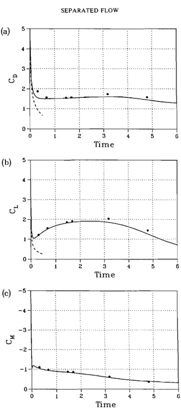
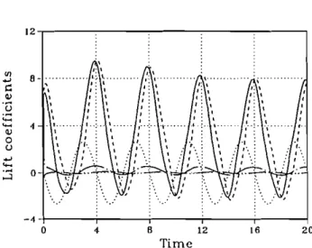
Now consider the dependence of CL on X and k . Figure I l(a-c) shows time histories of CL, CD and CM for X = 0.8 at various k . The higher the value of k , the more evident the periodic behaviour of the lift, drag and moment coefficients, and for
k >
0.15 the flow can be regarded as being dominated by the reduced frequency k .The amplitudes of CL, CD and CM all increase with increasing
k .
It is observed that the lift coefficient may become negative as k increases across about 0.16. It is interesting t o see that CM is always negative at large values of k and owns two peaks during a period of the motion of the ellipse. This indicates that the pressure distributions around the leading and trailing edges are always arranged to result in a negative pitching moment about the centre of the ellipse at large values of k.For further comparison of various coefficients at various A and k , we follow Maresca, Favier and Rebont (1979) by taking the averaged
CL
of the coefficients over a period of the motion of the ellipse. It is noted that averaging CL over a period is equivalent t o averaging C L W over the same period. In order t o relieve the influence of the impulsive start, the period for each case is taken t o begin with the first forward acceleration after the motion of the ellipse is started. Averaging is also made with the drag and moment coefficients t o yieldED
andEM.
Figure 12(a-c) presents the results. It is observed that the negative of increases withk
while the averagedED
orEL
tends t o acquire a maximum for a given A. The tendency is more obvious forEL
than for ED, and therefore for given A, the ratio of lift to drag decreases with increasing k . Roughly, we have, for a given X, a maximumEL
atXR
-
0.43 in the range of observation. Qualitatively, the behaviour of the averaged lift coefficient is found t o be in close comparison with that obtained by Maresca e t a / . (1979) at a = 20' for Reynolds numbers of the order l o S . Indeed the present study complements the work of Maresca er a / . in that the latter authors restrict themselves t o low reduced amplitudes (up t ok
= 1 . 6 1 2 ~ ) . Maresca, Favier and Rebont proposed a calculation of A and k leading t o maximum value ofEL
based o n the mechanism of vortex shedding. Such a calculation, however, does not seem t o apply here since vortex shedding alone is not the key element t o determine the magnitude of the vortex lift coefficient. However, at present we are neither able t o provide a simple theory for predicting the value 0.43. Finally, Figures 13 and 14 show the dependence of the lift coefficient on the angle of attack a and on the Reynolds number Re. It is found that the lift can be substantially increased byincreasing a from 20' to 30"; the gain is much less from 30" t o 40". Of particular interest is to see from Figure 14 that for the typical case X = 0.8 and
k
= 0.25, little difference can be found between Re = 500, 1000 and 3000 in the lift coefficients. It is therefore considered that the validity of the present results can be extrapolated t o higher Reynolds numbers. This more o r less explains why our results for theC.-C. CHANG A N D R.-L. CHERN
Time
(c) -I5 5 I I 1 I I 0 1 2 3 4 5 G TimeFigure I 1 (a) Variation o f Cr with k for X ~ 0 . 8 , (b) variatipn o f Co with
k
for X = 0 . 8 , ( c ) !ariation o f CM with k f o r A = 0 . 8 : - , k = 0 . 1 ; ---, k = O . Z ;...,
k = 0 . 3 ; - . - , k = 0 . 4 ; - . . - , k ~ 0 . 5 .SEPARATED FLOW
Figure 12 (a) Average
cL
vs. A,k.
(b) average CD vs. A,k,
(c) average CM vs. A,k:
0 , A = 0 . 4 ; 0,A = 0 . 6 ; 8 , A = 0 . 8 ; o , A = 1 . 0 ; A , A = 1 . 2 ; v , A = 1 . 4 ; P3, X = 1 . 6 ; 6 , A z l . 8 .
C.-C. CHANC AND R.-L. CHERN
Figure 13 Dependence of CL o n the angle o f a!tack:
--.
a = 20';---.
a = 30';. . .
, u = 40' ( A = 0.8.k = 0.25).
T i m e
Figure 14 Dependence of CL o n the Reynolds_nurnber: -, Re = 500; ---, 1000; .
. .
.
3000 ( A = 0.8,k = 0.25).
averaged lift coefficients bear much resemblance t o those obtained by Maresca, Favier and Rebont (1979) a t much higher Reynolds numbers.
6 . CONCLUDING REMARKS
In this paper, flow details around a two-dimensional ellipse and forces exerted on the body are studied from the viewpoint of vorticity. It proves useful t o apply the present force decomposition t o isolate the effect due t o the vorticity from that due
SEPARATED FLOW 303
t o the potential flow. The effects of individual vortices t o the force and moment coefficients can adequately be studied through the proposed vortex lift, drag and moment elements. This is of particular importance for flow with large separation since the flow may contain several vortices with concentrated vorticity. For large separation, the surface vorticity typically has little contribution t o the force and moment coefficients. Since all the elements involve the gradient of the potential flow besides the velocity and vorticity, it is interesting t o learn that the corresponding potential flow plays the geometric role in distributing the force (and moment) elements for the unsteady viscous flow. The behaviour of the averaged lift (drag and moment) coefficients is highly nonlinear with respect to X and k , denying simple analysis, and requires further investigation.
Ackno wledgemenr
The work is supported in part by the National Science Council, Taiwan, R.O.C. under Contracts NSC80-0401-E002-31 and NSC81-0401-E002-571.
Batchelor. G . K . (1967) An Introduction to Fluid Dynamics. Cambridge University Press.
Chang, C. C . (1989) Vortex methods and flow around a circular cylinder. In Numerical Methods in Laminar and Turbulenr Flow, vol. 6, (ed. C. Taylor, P . Gresho, R. Sani & J. Hauser), 691-700. Chang, C. C. and Chern, R. L. (1991) A numerical study of flow around an impulsively started circular
cylinder by a deterministic vortex method. J. Fluid Mech.. 233, pp. 243-263.
Davis, R. W. and Moore, E. F. (1982) A numerical study of vortex shedding from rectangles. J. Fluid Mech., 116, 475-506.
Gursul. I. and Ho. C. M. (1991) Hinh aerodvnamic loads on an airfoil submereed in an unsteadv stream. . -
(~"bmitted ti AIAA J.).
-
Ericsson, L. E. and Redding. J. P . (1987) Fluid dynamics of unsteady separated flow, Part 11. Lifting surfaces. Prog. Aero. Sci., 24, 249-356.
Kruppa, E. W. (1977) A wind tunnel investigation of the Kasper vortex concept. AIAA Paper 77-310. Lee, M. and Ho, C. M. (1990) Lift forces of delta wings. Appl. Mech. Rev., 43, 209-221.
Lugt. H . J. and Haussling, H. J . (1974) Laminar flow past an abruptly accelerated elliptic cylinder at 45' incidence. J. Fluid Mech.. 65, 711-734.
Maresca, C., Favier, D. and Rebont, J. (1979) Experiments on an airfoil at high angle of incidence in longitudinal oscillations. J. Fluid Mech., 91, 671-690.
McCroskey, W. J. (1982) Unsteady airfoils. Ann. Rev. Fluid Mech., 14, 285-311.
Ohmi, K., Coutanceau, M., Ta Phuoc Loc and Dulieu, A. (1990) Vortex formation around an oscillating airfoil at large incidences. J. Fluid Mech.. 211, 37-60.
Ohmi, K . . Coutanceau, M.. Ta Phuoc Loc and Dulieu, A. (1991) Further experiments on vortex formation around an oscillating and translating airfoil at large incidences. J. Fluid Mech.. 225. 607-630.
Patel. V. A. (1981) Flow around the impulsively started elliptic cylinder at various angles of attack. Computers and Fluids. 9, 435-462.
Peace, A. J. and Riley, N. (1983) A viscous vortex pair in ground effect. J. FIuidMech., 129, 400-426. Quartapelle, L. and Napolitano, M. (1983) Force and moment in incompressible flows. AIAA J., 21,
911-913.
Saffman. P. G. and Sheffield, J. S. (1977) Flow over a wing with an attached free vortex. Stud. in Appl. Math., 57, 107-1 17.
Walker, J. M . . Helin, H. E. and Strickland. J. H. (1985) An experimental investigation of an airfoil undergoing large-amplitude pitching motions. AIAA J.. 23, 1141-1 142.
Wang, C. Y. (1967) Separation and stall of an elliptic cylinder. Trans. ASME J. Appl. Mech., 34, 823-828.