配備頻寬平順技術之RTP/RTSP即時互動式多媒體串流監控系統設計與實作
133
0
0
全文
(2) 配備頻寬平順技術之 RTP/RTSP 即時互動式多媒體串流監控系統 設計與實作 Design and Implementation of a Real-time Interactive RTP/RTSP Multimedia Streaming Monitoring System with Bandwidth Smoothing Technique 研 究 生:陳建華. Student:Chien-hua James Chen. 指導教授:張文鐘 博士. Advisor:Dr. Wen-Thong Chang. 國 立 交 通 大 學 電 信 工 程 學 系 碩 士 論 文 A Thesis Submitted to Department of Communication Engineering College of Electrical Engineering and Computer Science National Chiao Tung University in Partial Fulfillment of the Requirements for the Degree of Master of Science in Communication Engineering August 2005 Hsinchu, Taiwan, Republic of China. 中華民國九十四年八月.
(3) 配備頻寬平順技術之 RTP/RTSP 即時互動式多媒體串流監控系統 設計與實作 研究生: 陳建華. 指導教授: 張文鐘 博士. 國立交通大學電信工程學系碩士班 摘要 多媒體串流(Streaming)技術的目的,是使消費者在下載多媒體檔案的同時, 可以先觀賞已收到的部份,而不需要等到完整下載後,才開始觀賞。目前最被廣泛 接受的串流通訊協定是 Real Time Protocol(RTP),它是針對即時串流的特殊需求所 設計的。此協定也可搭配 Real Time Streaming Protocol (RTSP)使用。RTSP 提供 Server 與 Client 之間的雙向溝通,Client 可以透過 RTSP 下指令給 Server 作像是 「播放」 、 「暫停」 、 「停止」等動作。市面上有許多軟體廠已有解決方案,此些 Servers 都符合 RTP 及 RTSP 的規範,但只提供單純的多媒體檔案串流。此些 Servers 無 法支援如即時串流無線攝影機所或 USB 攝影機所拍攝到的影像,或將變動位元速 率 (Variable-bit-rate) 的多媒體檔案,做規劃平整 (Smoothing) 的動作,來達到較 平順的傳送等。 本論文針對此需求,提出一套符合 RTP 及 RTSP 且可以很輕易被擴充功能的 Client/Server 軟體系統平台 。在本系統裡,Server 端可以向各種攝影機擷取影像 及聲音,即時的壓縮到 MPEG-4 的格式,儲存或馬上串流到多個 Clients。Client 可向 Server 要求串流攝影機的即時影像和聲音,或已儲存的多媒體檔案等。Client 如果要求的是已儲存的檔案,Server 會先針對 Video 的統計特性,做頻寬平整的動 作,達到較佳的串流效果及網路資源的利用。Client 若為監控中心,因為此系統提 供簡單的軟體輸出/輸入界面,所以可在系統上輕鬆的加裝影像處理程式,達到自動 化監控的效果。本論文將仔細地介紹此系統的架構、設計想法及使用方法,尤其會 特別闡述如何使 Server 可以在非常準確的時間,將每張 frame 傳送出去。 本文所提出的目標及期望達到的功能都已達到和實現。然而,在觀察 Server 的傳送情況後發現,每張 frame 被傳送出去的時間準確度並不理想,且此誤差在多 個 clients 連線時將更明顯。本文在最後將提出可改善此系統的方向及未來可努力的 目標。. -i-.
(4) Design and Implementation of a Real-time Interactive RTP/RTSP Multimedia Streaming Monitoring System with Bandwidth Smoothing Technique Student: Chien-hua James Chen. Advisor: Dr. Wen-Thong Chang. Department of Communication Engineering National Chiao Tung University. Abstract Streaming technology allows people to enjoy the multimedia contents while still downloading. Up to date, the most widely used and accepted streaming protocol is Real Time Protocol (RTP), which is specially designed for the needs of real-time streaming, and can be used in conjunction with Real Time Streaming Protocol (RTSP). RTSP provides bidirectional communication between the server and the client. Several software companies have come out with their streaming solutions that comply with RTP and RTSP. However, they merely fulfill the needs of streaming stored media files. They can neither stream real-time captured video/audio acquired from various types of cameras, nor transmit VBR multimedia contents in a smoother manner. In this work, an RTP/RTSP-compliant client/server streaming system that is flexible enough to be added with new functions is implemented. In particular, the server can acquire audiovisual data from different kinds of cameras, real-time encoding them into MPEG-4 format, and store or stream the resulted bitstreams to multiple clients. The client can ask the server to stream live-captured or stored media contents. If the client requests the stored video, the server can run the smoothing algorithm to smoothen the VBR traffic, so a better streaming experience and more efficient utilization of network resources can be obtained. Since the client software is designed to provide a clean and easy-to-use software input/output interface, image processing functions can be added to it effortlessly to allow automotive monitoring of unattended areas. Certainly, the architectures, design ideas, and the usages of the client and server systems will be explained in details. How the server can stream data following tight timing constraints will be addressed specifically. Apparently, the proposed goals are achieved and expected functions are realized. However, it is observed at the server side that the inter-departure times between frames are not equal to the expected values. This discrepancy becomes more obvious when more clients are present. Finally, possible ways to enhance the proposed system and the directions of the future work will be suggested.. -ii-.
(5) Acknowledgements I would like to express my deepest gratitude to my academic and research advisor Dr. Wen-Thong Chang for his guidance and constant support in helping me conduct and complete this work. I would also like to thank my colleagues in Wireless Multimedia Communication Laboratory for their active participation in this research. Many thanks to all the people I have come to know in National Chiao Tung University, whose friendship and companionship I will always enjoy.. I owe my sincere appreciation to my families and relatives who have supported and encouraged me over the years. I especially want to thank Dephnie Li for her inspiration and continuous encouragement during my studies. Most important of all, I want to extend my profound appreciation to my beloved parents and families, for their love, affection, and invaluable support during my life and studies.. -iii-.
(6) Table of Contents 摘要........................................................................................................................ i Abstract................................................................................................................. ii Acknowledgements.............................................................................................. iii Table of Contents ................................................................................................. iv Lists of Figures..................................................................................................... vi List of Tables .......................................................................................................viii Acronyms ............................................................................................................. ix 1 Introduction ........................................................................................................1 1.1 Background..............................................................................................1 1.2 Motivations...............................................................................................4 1.3 Research Goals .......................................................................................4 1.4 Thesis Outline..........................................................................................4 2 Streaming Technologies ....................................................................................5 2.1 The Real-time Transport Protocol ............................................................5 2.1.1 RTP ...............................................................................................6 2.1.1.1 RTP Packet Format .............................................................6 2.1.1.2 RTP Example.......................................................................8 2.1.2 RTCP .............................................................................................9 2.1.2.1 RTCP Packet Types ............................................................9 2.1.2.2 RTCP Sending Rules.........................................................10 2.1.2.3 RTCP Packet Formats....................................................... 11 2.2 The Real Time Streaming Protocol ........................................................20 2.2.1 Supporting Operations.................................................................21 2.2.2 Properties ....................................................................................21 2.2.3 RTSP States ................................................................................22 2.2.4 Method Definitions .......................................................................23 2.2.5 RTSP Status Codes .....................................................................29 2.2.6 A Typical RTSP Unicast Session Example...................................31 2.3 Introduction to Traffic Smoothing Algorithms .........................................32 2.3.1 MVBA ..........................................................................................33 2.3.2 Packet-based MVBA....................................................................35 3 Some Programming Techniques......................................................................37 3.1 Threads..................................................................................................37 3.2 Mutex and Semaphores.........................................................................38 3.3 Token Bucket.........................................................................................39 4 Streaming System Implementation ..................................................................40 4.1 System Development Environment........................................................40 4.1.1 Hardware Requirements ..............................................................40 4.1.2 Software Requirements ...............................................................40 4.1.3 Hardware Setup...........................................................................41 4.1.4 Software Setup ............................................................................41 4.2 Expected System Capabilities ...............................................................42 4.2.1 Expected Capabilities of Server System......................................42 4.2.2 Expected Capabilities of Client System .......................................43 4.3 System Architecture...............................................................................44 4.3.1Architecture of Streaming Server System.....................................46 4.3.1.1 Threads Used in Streaming Server System.......................49. -iv-.
(7) 4.3.2 Architecture of Streaming Client System .....................................51 4.3.2.1 Threads Used in Streaming Client System ........................53 4.4 Graphical User Interface Thread............................................................54 4.4.1 Control Items Required................................................................55 4.4.2 Members of RTSPStreamServer Class .......................................57 4.4.3 Members of RTSPStreamClient Class.........................................58 4.4.4 Transcoder Thread ......................................................................61 4.4.5 StatusTimeFunc ...........................................................................62 4.4.6 VideoStatusTimeFunc and AudioStatusTimeFunc .......................62 4.5 Implementation of RTSP Messages and State Changes .......................64 4.5.1 OverallListenerThread .................................................................65 4.5.2 RTSPProcessorThread................................................................68 4.5.2.1 handle_server_event .........................................................69 4.5.2.2 handle_client_event...........................................................70 4.6 Implementation of RTP Streaming .........................................................71 4.6.1 RTP Transmission Channel Setup...............................................71 4.6.2 Packetizer and De-Packetizer .....................................................73 4.6.3 Streaming Control........................................................................74 4.6.3.1 Implementation of Streaming Control ................................75 4.6.3.2 Important Variables, Their Meanings, and Their Initial Values ......................................................................................................79 4.6.3.3 Software Implementation to Calculate the Start Time ........80 4.6.4 Bandwidth Smoothing..................................................................82 4.7 Assembling Pieces.................................................................................83 5 Usages of Modules ..........................................................................................91 5.1 Using 3GP Parser module .....................................................................91 5.1.1 Getting started with 3GP Parser module......................................91 5.1.2 The complete API ........................................................................93 5.2 Using 3GP Creator module....................................................................95 5.3 Using Sub Server module ......................................................................96 5.3.1 Getting started with Sub Server module ......................................96 5.3.2 The complete API ........................................................................97 5.4 Using Sub Client module .......................................................................99 5.4.1 Getting started with Sub Client module........................................99 5.4.2 The complete API ......................................................................100 6 System Execution ..........................................................................................104 6.1 Server Interface ...................................................................................105 6.2 Client Interface.....................................................................................105 6.3 Results of Executions ..........................................................................106 6.4 Observations on Server Transmission Behavior.................................. 111 6.5 Discussions.......................................................................................... 115 7 Conclusions ................................................................................................... 117 References .......................................................................................................121. -v-.
(8) Lists of Figures Figure 1. –. RTP Packet Format………………...…………………………..….6. Figure 2. –. RTP Header Format………………………..…………...….……...7. Figure 3. –. An example of using SSRC, CSRC, and Mixer……..…………..9. Figure 4. –. A typical compound RTCP packet……………………….…......10. Figure 5. –. Format of Receiver Report………………………..............…….12. Figure 6. –. Calculation of Round-trip delay………………………………….14. Figure 7. –. Format of Receiver Report…………………………………....…15. Figure 8. –. Format of SDES…………………………………………….....….15. Figure 9. –. Format of CNAME item………………………………………..…16. Figure 10. –. Format of NAME item…………………………….………………16. Figure 11. –. Format of EMAIL item………………………………………..…..17. Figure 12. –. Format of PHONE item……………………………….……….…17. Figure 13. –. Format of LOC item………………………………..…………..…17. Figure 14. –. Format of TOOL item…………………………….…….…………18. Figure 15. –. Format of NOTE item…………………………….………………18. Figure 16. –. Format of PRIV item…………………………………..…….……18. Figure 17. –. Format of BYE………………………………………..…..…….…19. Figure 18. –. Format of APP……………………………………………….……19. Figure 19. –. RTSP State Machine………………………..……………………23. Figure 20. –. A typical RTSP unicast session example………………....……31. Figure 21. –. Illustration of token bucket………………………………......…..39. Figure 22. –. Illustration of system hardware setup…………………...……...41. Figure 23. –. Tasks that the server must handle in the proposed system…..43. Figure 24. –. Tasks that the client must handle in the proposed system.…..44. Figure 25. –. Illustration of client/server system with RTP and RTSP in use………………………………………………………………….45. Figure 26. –. Architecture of server system……………………………………47. Figure 27. –. Threads of server system………………………….……...…..…49. Figure 28. –. Architecture of client system……………………………...….….52. Figure 29. –. Threads of client system……………………………………...….53. -vi-.
(9) Figure 30. –. Relationships between GUI and underlying modules…………57. Figure 31. –. When “Start” button is pressed……………………...…….….…58. Figure 32. –. When “Open” button is pressed…………………...………….…59. Figure 33. –. Illustration of multiple RTSP sessions connecting to a server..67. Figure 34. –. Threads present when both server and client programs start………………………………………………………………...89. Figure 35. –. Threads present when server starts its service and client connects to it………………………………………………………89. Figure 36. –. Threads present when RTSP message exchanges are in Progress……………………………………………….………..…89. Figure 37. –. Threads present when both RTSP and RTP via UDP are in progress…………………………………..………….……………90. Figure 38. –. Threads present when both RTSP and RTP via TCP are in progress……………………………………………….…..………90. Figure 39. –. Typical usage of 3GP Parser module……………………….….91. Figure 40. –. Server interface………………………………….…………..….104. Figure 41. –. Client interface……………………………………...…....….….106. Figure 42. –. Server interface when connecting to two wireless cameras and one USB camera………………..………………………………107. Figure 43. –. Server interface when four clients are connecting to it.......…108. Figure 44. –. Client interface when acquiring live-captured contents….….109. Figure 45. –. Client interface when acquiring stored contents……......……110. Figure 46. –. Using Windows® Media Player® as Clients……………….....111. Figure 47. –. Histogram of inter-departure times between groups of packets when streaming to one client…..............................................112. Figure 48. –. Histogram of inter-departure times between groups of packets when streaming to six clients….............................................113. Figure 49. –. Transmission rate for unsmoothed traffic…………..………...114. Figure 50. –. Transmission rate for smoothed traffic with 2MB client Buffer………………………………………………………..……114. -vii-.
(10) List of Tables Table 1 –. Overview of RTSP methods, their directions, and what objects they operate………………………………………………………….………24. Table 2 –. Status codes and their usage with RTSP methods……………….30. -viii-.
(11) Acronyms API. Application program interface. CBR. Constant-bit-rate. IETF. Internet Engineering Task Force. MTU. Maximum transmission unit. MJPEG Motion JPEG MPEG. Motion Picture Experts Group. MVBA. Minimum Variance Bandwidth Allocation. RCBS. Rate-Constrained Bandwidth Smoothing. RTCP. The RTP Control Protocol [part of RFC3550]. RTP. The Real-time Transport Protocol [RFC3550]. RTSP. The Real Time Streaming Protocol [RFC2326]. URI. Uniform Resource Identifier. VBR. Variable-bit-rate. -ix-.
(12) 1 Introduction 1.1 Background With wide spread of network infrastructure and extensive usage of both wired and wireless devices, consumers can enjoy multimedia contents on their PCs, set-top boxes, Digital TVs, and mobile phones at any time and any place.. For example, the user can. use his or her PC to download the latest episode of Star Wars from one of the content providers. When the downloading process is completed, the user can start watching the movie. This is extremely convenient because the user does not need to go out when he or she feels lazy or it is raining outside. The user is only one “press” away from enjoying the high resolution media contents. This way of retrieving and enjoying the media contents is referred as the traditional downloading method. So far, the story sounds terrific and seems to end perfectly. However, in fact, the story is not even close to what it looks like. For instance, what if one is in the coffee shop and suddenly wants to watch a movie of two-hour long? Can he or she wait there for the completion of downloading? Two-hour move is usually of size greater than 1 GB, and if only IEEE 802.11b (11Mbps) wireless network is available in the coffee shop, he or she will have to wait for approximately 10 to 20 minutes if the network is not congested. If the network is shared by multiple users (congested), which is often the case, he or she will need to wait a lot longer. For another example, what if one is using a handheld device (e.g. a PDA or mobile phone) that has much lower transmission rate and much lesser memory space (around 256 to 512 MBs)? He or she will have to wait for couple of hours to download the complete movie. In addition, the worst thing is that the memory is not even sufficient to store the complete media file! To overcome this serious problem, the technology called “streaming” has been developed. Instead of transmitting the whole file, the content server will divide the media file into tiny minipackets (usually around 1024 bytes), and transmit them to the user according to the transmission schedule specified for the file. When the player that the user is using receives the stream of packets, it will start to render them on the display device. Thus, the streaming technology allows one to start watching or listening to the media content as soon as he or she has received a certain amount of the content. Of course, the content provider has to continuously transmit the remaining data with the -1-.
(13) transmission rate equal to or higher than the playback rate to guarantee smooth (no delay) presentation at his or her display device. The major distinction between “streaming” and the traditional downloading is that the former offers “play while downloading” while the later merely provide “play after downloading”. In short, streaming enables playback of audiovisual content in real time, while with the traditional downloading method, the entire file has to be retrieved before playback begins. Actually, media streaming has emerged as an important service offered over the Internet in these days. There are two types of streaming: pseudo streaming and true streaming [1]. The former replies on the TCP/IP, the Internet protocol used for conventional web pages, while the later employs, up to date, the most widely used and accepted streaming protocol, Real Time Protocol (RTP) [2], which is defined in RFC-3550 by Internet Engineering Task Force (IETF),and is specially designed for the needs of real-time streaming. According to [2], RTP provides end-to-end delivery services including payload type identification, sequence numbering, timestamping, and transmission monitoring, for multimedia data with real-time properties, such as video and audio. Typically, RTP does not work on its own but do rely on and run on top of suitable underlying network such as UDP (primarily) or TCP. Moreover, RTP consists of two major components: z. The real-time transport protocol (RTP), which carries real-time data.. z. The RTP control protocol (RTCP), which monitors reception quality and exchanges information about the participants in an active session. RTP can be used in conjunction with Real Time Streaming Protocol (RTSP) [3],. which is defined in RFC-2326 by IETF and layered on top of RTP. RTSP acts as a “network remote control” to provide bidirectional communication between the server and the client similar to HTTP. According to [3], RTSP establishes and controls one or more than one time-synchronized stream of media data. For example, in a client/server scenario with RTSP functionalities, the client can issue “PLAY”, “PAUSE, and “STOP” requests to control the streaming process of the server. Since the streaming technology has been realized on RTP and enhanced by RTSP, and high-speed network infrastructure has been widely spread, one may think of the application that for some places like wards in hospitals or rooms with unattended sick. -2-.
(14) elders (targeted areas or places) that need to be automatically monitored because of limited budget to hire caretakers or a shortage of nurses, several wireless cameras can be installed to help monitor the status of these targeted areas. These cameras will send their captured audiovisual contents to a centralized streaming server in real time. The client system with automotive image processing functions can ask the server to stream these live captured contents to it, so it can analyze the contents. When discovering abnormal events, the client system may notify the related personnel by sending him or her an SMS or email. The related personnel, upon receiving the notification, will connect to the streaming server immediately to receive the stored or the most recently recorded audiovisual contents, and perform the necessary actions. To realize this application, at first thought, the system designer may want to use one of the free streaming servers available in the market. In fact, at present several software companies have come out with their streaming solutions, such as the Media Server and Player from Microsoft, the Helix Server and Player of Real, and the Darwin Streaming Server and QuickTime Player of Apple. These solutions do comply with RTP and RTSP, but however, they only fulfill the need of streaming stored multimedia contents. They neither can work with various kinds of cameras, nor stream live-captured audiovisual contents. In addition, they do not provide automotive image processing functions for surveillance purpose. Furthermore, to enhance the streaming experience, the system designer may want to control the actual streaming process. For example, the system designer can adapt the transmission rate to the congestion level of the network. In reality, due to the VBR nature of the common media contents, it is not easy to allocate the network resources for streaming. The burstiness of these contents does add burden to the network. Therefore, a streaming control technique called “smoothing” has been developed to overcome this disadvantage. Its task is to smoothen the VBR traffic so that the traffic will behave CBR-like. However, the aforementioned commercial solutions do not adopt this concept into their transmission control. Therefore, it is necessary to implement an RTP/RTSP-compliant client/server streaming system that can work with any type of camera, provide simple interface for image processing software developers to embed their programs into the client system, and offer the options of whether to turn on the smoothing function or not.. -3-.
(15) 1.2 Motivations The motivations of this work are as the following: z. Commercial streaming systems cannot support streaming of live-captured audiovisual contents acquired from various types of cameras.. z. Image processing programs allow the surveillance system to monitor unattended targeted places automatically. However, the commercial streaming solutions do not offer this function.. z. The VBR characteristic of media contents adds burden to the network, so their transmission schedules should be smoothened by smoothing algorithm. However, the commercial streaming solutions do not adopt this concept.. 1.3 Research Goals The goals of this research are as follows: z. Implementing a client/server system that is fully compliant with RTP and RTSP.. z. Designing the system in such a way that it provides the options of whether to turn on the smoothing functions or not.. z. Designing a simple software interface for the client system in such a way that image processing algorithms can be added to it in an effortless manner.. z. Describing how to build, organize, and use this system.. z. Discussing the execution of the system.. 1.4 Thesis Outline The organization of this paper is as follows. We survey the current available streaming servers developed by Apple, Real, and Microsoft in Chapter 2. In Chapter 3, RTP and RTSP are introduced and discussed, and some programming techniques needed to implement the system are mentioned and explained. The implementation details, usage of the system, and execution results are presented in Chapter 4. At last, this project is concluded in Chapter 5.. -4-.
(16) 2 Streaming Technologies In this section of the paper, streaming technologies involved to design and implement the proposed client/server streaming system will be discussed. In particular, the Real-time Transport Protocol (RTP) [2], its subpart, the RTP Control Protocol (RTCP) [2], and Real Time Streaming Protocol (RTSP) [3] will be addressed in detail.. 2.1 The Real-time Transport Protocol In a client/server media streaming system, if video/audio data are transmitted using The Transmission Control Protocol (TCP) from a server to a client, intolerable delay will be introduced frequently in the case of packet losses. This drawback results from the fact that TCP always recovers these losses by retransmitting lost packets to provide reliable service, so the client must wait for receipt of all retransmissions. If this waiting time is significantly long, the client’s playback buffer will soon be empty and the player will stop playback since it runs out of contents, causing extremely unpleasant viewing experiences. Thus, although TCP guarantees delivery of data but does not guarantee timely delivery as this retransmission mechanism causes additional end-to-end packet delay. One of the solutions to solve this problem is to use a more light-weight but unreliable protocol, The Datagram Protocol (UDP). UDP, unlike TCP, does not support automatic retransmission, and cannot be used to detect or signal packet losses. Hence, UDP cannot adapt itself to the changing network conditions. However, in a congested network where packet losses do occur, it does provide a faster transmission than TCP. The Real-Time Transport Protocol (RTP) [2] is a protocol which can compensate for the missing functions of UDP. It is usually used on top of UDP to make use of UDP’s multiplexing and checksum services [2]. In fact, its packets are usually encapsulated in UDP packets. According to [2], RTP provides end-to-end delivery services for data with real-time characteristics, such as interactive audio and video. The services provided include content type identification, sequence numbering, timestamping and monitoring QoS of data transmission. The detailed descriptions about RTP will be given in the following sections. RTP consists of two tightly-linked protocols: RTP for transmission of data with real-time properties and RTP Control Protocol (RTCP) for monitoring QoS of -5-.
(17) transmission and for conveying participants' information in a session [2].. 2.1.1 RTP RTP provides end-to-end network transport functions suitable for applications transmitting real-time data, such as audio/video, over multicast or unicast network services. Its main purpose is to carry real-time audiovisual data. In other words, media data are packetized into several RTP packets in the format specified in the following section. These RTP packets are passed down to the lower layer protocol like UDP, which in turn, transmit them to the client side.. 2.1.1.1 RTP Packet Format As can be seen from Figure 1, RTP packets consist of a header followed by payload data which can be either a portion of video frame or audio samples. How different types of video/audio data are formatted to be carried by RTP packets is specified in payload format specification documents. For example, 3GPP MPEG4 AV payload format is defined in RFC3016 and Simple MPEG4 AV payload format is defined in RFC3640.. Figure 1 – RTP Packet Format. Referring to Figure 2, an RTP header has the following fields: z. Version (V): 2 bits It specifies the version of RTP. The Value 2 is set for RFC3550.. z. Padding (P): 1 bit It indicates whether this packet contains padding bytes at the end. Padding may be necessary for some encryption algorithms or for carrying several RTP packets in a lower-layer data unit. The last byte of the padding stores the number of padding bytes that should be ignored including itself.. -6-.
(18) Figure 2 – RTP Header Format [2] z. Extension (X): 1 bit This bit is set when exactly one header extension is placed after the fixed header. The header extension is to allow individual implementations to conduct experiments.. z. CSRC count (CC): 4 bits Contributing source (CSRC) is a source of a stream that contributes to the combined stream produced by a mixer. A mixer combines the packets from one or more sources in some manner, and forwards a new combined RTP packet. CC represents the number of CSRC sources of this RTP packet. The ideas of a mixer and the CSRC will become apparent in Section 3.1.2.2.. z. Marker (M): 1 bit It is used to indicate the important events such as frame boundaries.. z. Payload type (PT): 7 bits It identifies the format of the payload.. z. Sequence number: 16 bits This number increments monotonically each time an RTP packet is sent. Its initial value should be random to avoid know-plaintext attacks on encrypted data. It can be used by the receiving end to detect packet loss or re-order out-of-sequence packets.. z. Timestamp: 32 bits It reflects the instant when the first byte of the payload data is sampled for applications transmitting live-captured data, or when the payload data should be. -7-.
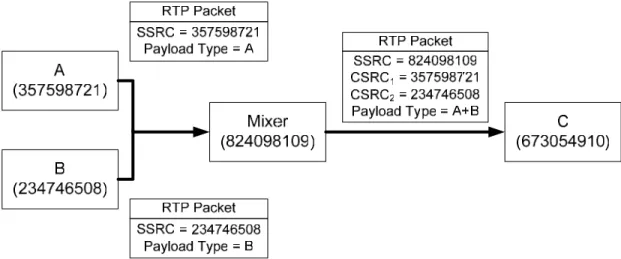
(19) presented for applications transmitting stored data. As it reconstructs the timing of a single stream, it is used when performing synchronization or jitter calculation. Its initial value should be random to avoid know-plaintext attacks on encrypted data. Note that timestamps for different media streams may advance at different rates and usually have independent, random offsets. z. SSRC: 32 bits Synchronization source (SSRC) is the source of a stream of RTP packets. Its value is randomly selected to be globally unique within a particular RTP session. So if a single sender generates multiple streams in one RTP session, the possible confusion caused by only having a single network address can be avoided because the sender will have several distinct SSRC identifiers.. z. CSRC list: 0 to 15 items, 32 bits each It is a list of CSRCs which contribute to the payload of this RTP packet.. 2.1.1.2 RTP Example To illustrate the notion of SSRC, CSRC, and a mixer more clearly, Figure 3 is presented. In the figure, participants A, B, and C, each having its own unique SSRC, are hosting a conference in an RTP session. Assume that the speed of the links between A and the mixer, and B and the mixer is high, while the bandwidth between the mixer and C is low. Obviously, C cannot enjoy high-speed network access like A or B. Instead of forcing all participants to transmit and receive poor-quality conference data, a mixer can be placed near C. In such arrangement, A and B can still enjoy their high-quality conference, because that the mixer, when receiving high-quality conference data from A and B, can translate, resynchronize, and combine these data into lower-bitrate ones, and forward them to C across the lower-speed link.. -8-.
(20) Figure 3 – An example of using SSRC, CSRC, and Mixer. 2.1.2 RTCP RTCP monitors the data delivery in a manner scalable to large multicast networks, and provides minimal control and identification functionality [2]. It is based on the periodic exchanges of control packets between all participants in an RTP session. According to [2], RTCP provides the following three key functions: z. It gives feedbacks on the reception quality of a session by transmitting RTCP sender and receiver reports, as described in following section.. z. It carries a canonical name (CNAME) for each participant. As the SSRC identifier of a participant may change if a conflict occurs or when a program is restarted, receivers need CNAME to keep track of each source.. z. It can help the sender and the receiver adjust their clock drifts.. 2.1.2.1 RTCP Packet Types RTCP has five packet types: z. SR: - Sender report, for senders to transmit their transmission and reception statistics.. z. RR: - Receiver report, for receivers to transmit their reception statistics, including number of lost packets, highest sequence number received, jitter, and other delay measurements to calculate the round-trip delay time.. z. SDES: -9-.
(21) - Source description items, including CNAME. z. BYE: - Indication of end of participation. z. APP: -Application-specific functions. 2.1.2.2 RTCP Sending Rules To reduce the bandwidth consumption required by RTCP packets, multiple RTCP packets from a single participant can be concatenated to form a compound RTCP packet. Therefore, each RTCP packet must end on a 32-bit boundary to be stackable. There are two constraints that must be followed: z. Each compound RTCP packet must contain a report packet (SR or RR) to maximize the resolution of reception statistics, and this report packet must be the first to appear to facilitate header validation.. z. Each compound RTCP packet must include SDES CNAME, so new receivers can identify sources of streams and begin to synchronize the media data streams as soon as possible. In another case, as the SSRC identifier of a participant may change if a conflict occurs or when a program is restarted, receivers need CNAME to keep track of each source.. In Figure 4, a typical compound RTCP packet is presented. Observe that at least one report packet and SDES CNAME are included.. Figure 4 – A typical compound RTCP packet. There are few general sending rules for RTCP packets [2]: z. The Traffic generated by RTCP should occupy 5% of an RTP session bandwidth.. z. Sender reports should occupy one-forth of the RTCP bandwidth.. z. The target interval between two RTCP packets must be larger than 5 seconds. However, the actual RTCP interval should be varied over the range between half and 1.5 times of the target interval. -10-.
(22) 2.1.2.3 RTCP Packet Formats Sender Report Sender reports are used to provide reception quality feedback and senders’ information by participants who are senders, and possibly receivers at the same time. Referring to Figure 5, a sender report consists of three sections: the header, the sender info, and the report blocks. The fields in the header section are: z. Version (V): 2 bits - It specifies the version of RTP. The Value 2 is set for RFC3550.. z. Padding (P): 1 bit - It indicates whether the compound RTCP packet contains padding bytes at the end of last individual RTCP packet. Padding may be necessary for some encryption algorithms.. z. Reception Report Count (RC): 5 bits - It counts the number of reception report blocks contained in this compound RTCP packet.. z. Packet Type (PT): 8 bits - Its value is set to 200 to identify this packet as an RTCP SR packet.. z. Length: 16 bits - It represents the length of this RTCP packet including the header, the sender into, the report blocks, and any padding.. z. SSRC: 32 bits - It indicates the synchronization source (SSRC) identifier for the originator of this sender report.. -11-.
(23) Figure 5 – Format of Receiver Report [2]. The sender information block contains the following fields. z. NTP Timestamp: 64 bits - It indicates the wallclock time in Network Time Protocol (NTP) format, which is in seconds relative to 00:00 UTC on January 1st, 1990, when this report was sent. The integral part is in the first 32 bits and the fractional part is in the last 32 bits.. z. RTP Timestamp: 32 bits - It represents the same time instant as the NTP timestamp but is in the same units. -12-.
(24) and random offset as the RTP timestamps in RTP packets. With RTP timestamps, intra-media and inter-media data can be synchronized for sources whose NTP timestamps are in synchronization. z. Sender's Packet Count: 32 bits - It contains the total number of RTP packets sent by the sender since the start of the transmission until now.. z. Sender's Octet Count: 32 bits - It contains the total number of RTP data payload bytes sent by the sender since the start of the transmission until now.. The third section contains zero or more reception report blocks that have the following fields: z. SSRC_n (source identifier): 32 bits - It indicates the SSRC identifier of the source to which this reception report block is meant.. z. Fraction Lost: 8 bits - It shows the percentage of RTP packets lost from SSRC_n since previous SR or RR was sent.. z. Cumulative Number of Packets Lost: 24 bits - It contains the total number of RTP packets lost from SSRC_n since the start of the transmission until now.. z. Extended Highest Sequence Number Received: 32 bits - The lower 16 bits represent the highest sequence number received from SSRC_n, and higher 16 bits show the number of sequence number wrap-ups.. z. Interarrival Jitter: 32 bits - This field is an estimation of the statistical variance of RTP packet interarrival time, measured in timestamp units. Let Si and Ri be the RTP timestamp and the time of arrival of ith RTP packet, respectively. Let D(i,j) be the variation between the difference of ith and jth RTP packets’ timestamps and the difference of these two packets’ arrival times. Thus, D(i,j) can be computed as follows:. -13-.
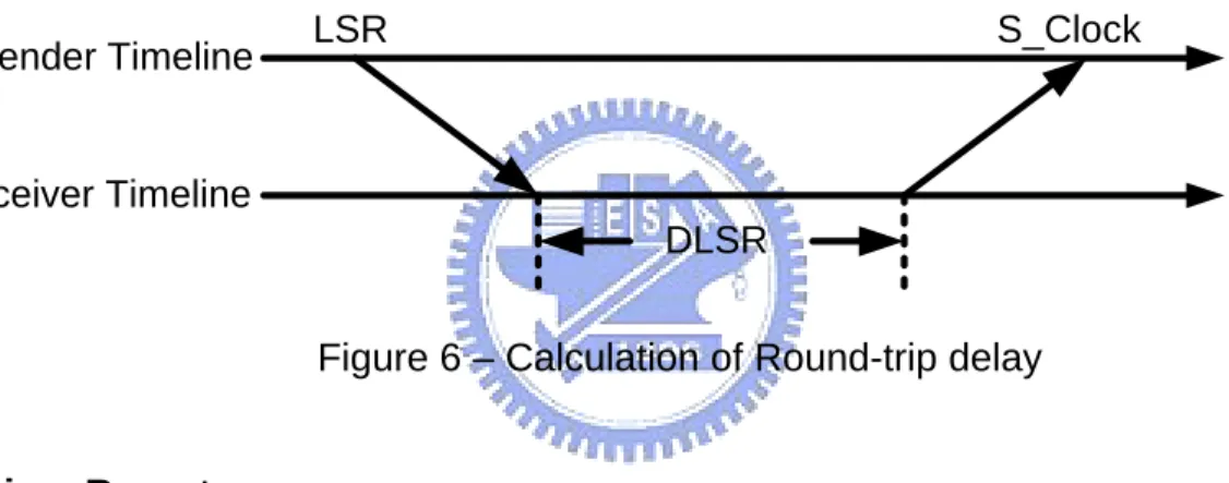
(25) The interarrival jitter should be calculated constantly as the following whenever an RTP packet arrives from SSRC_n: z. Last SR timestamp (LSR): 32 bits -. This field contains the center 32 bits out of 64 bits in the NTP timestamp included. in the most recent SR from SSRC_n. z. Delay since last SR (DLSR): 32 bits - This field is the difference between the time the last SR was received and the time this reception report is generated. Referring to Figure 6, upon receiving this information, the sender can compute the round-trip propagation delay as RTT = (S_Clock – LSR) – DLSR, where S_Clock is the time this report is received.. Sender Timeline. LSR. S_Clock. Receiver Timeline DLSR. Figure 6 – Calculation of Round-trip delay. Receiver Report The purpose of the receiver report is identical to that of the sender report. Unlike the sender report, the receiver report is targeted for the receiver who is not also a sender at the same time. As can be observed from comparing Figure 7 with Figure 5, a receiver report is almost identical to a sender report except that the packet type field in a receiver report is 201, and that a receiver report does not contain the sender information. Therefore, the receiver report’s format will not be explained in detail here.. -14-.
(26) Figure 7 – Format of Receiver Report [2]. SDES. Figure 8 - Format of SDES [2]. Referring to Figure 8, an SDES packet consists of a header and zero or more -15-.
(27) chunks, each of which is composed of items describing the source that this chunk is designated to. In the header section of a SDES packet, following fields are present: z. Version (V), Padding (P), Length: - They are the same as those defined in the format of SR packet.. z. Packet Type (PT): 8 bits - Its value is set to 202 to identify this as an SDES packet.. z. Source count (SC): 5 bits - It is the number of SSRC/CSRC chunks contained in this SDES packet.. There are eight types of items but only CNAME is mandatory. Each type of item is composed of the type, the length, and the text. . CNAME: Canonical End-Point Identifier SDES Item. Figure 9 – Format of CNAME item [2] CNAME item should be formatted as in Figure 9. CNAME is used to eliminate the ambiguity caused when having SSRC conflicts. It must be included in each compound RTCP packet to provide the binding between SSRC and CNAME. Therefore, it should be unique among all participants within a session, remain unchanged during the lifetime of a session, and be derived algorithmically. For example, a CNAME can be “[email protected]” or “[email protected]”, where the part before ‘@’ is the user name and the part after ‘@’ is the host name.. Figure 10 – Format of NAME item [2]. -16-.
(28) . NAME: User Name SDES Item. NAME item should be formatted as in Figure 10. It contains the real name of the source. For example, it can be “James Chen”. . EMAIL: Electronic Mail Address SDES Item. Figure 11 – Format of EMAIL item [2] EMAIL item should be formatted as in Figure 11. It contains the email address of the source and is expected to remain fixed for the lifetime of a session. For example, it can be “[email protected]”. . PHONE: Phone Number SDES Item. Figure 12 – Format of PHONE item [2] NAME item should be formatted as in Figure 12. The phone number of the source should be formatted with a plus sign in front replacing the international access code. For instance, it can be “+1 416 224 8736”, which is a phone number in Toronto, Canada. . LOC: Geographic User Location SDES Item. Figure 13 – Format of LOC item [2]. -17-.
(29) LOC item should be formatted as in Figure 13. The degrees of details depend on the applications and should be left to the application users. This item should remain unchanged for the lifetime of the session, except for mobile participants. . TOOL: Application or Tool Name SDES Item. Figure 14 – Format of TOOL item [2]. TOOL item should be formatted as in Figure 14. The name/version should be those of the application that is generating the stream, for example, “Skype”, and should remain unchanged for the lifetime of the session. . NOTE: Notice/Status SDES Item. Figure 15 – Format of NOTE item [2]. NOTE item should be formatted as in Figure 15. It describes the current status of the source, for example, “busy” or “active”. . PRIV: Private Extensions SDES Item. Figure 16 – Format of PRIV item [2]. PRIV item should be formatted as in Figure 16. It is used to define trial or application-specific SDES functionalities. It contains a prefix including a length-string -18-.
(30) pair. The prefix length field describes the length of the prefix string, which is a name chosen to be unique with respect to other PRIV items that might be received. The value string field carries the desired data. BYE. Figure 17 - Format of BYE [2] A BYE RTCP packet signifies one or more sources’ terminations. Referring to Figure 17, it contains the following fields: z. Version (V), Padding (P), Length: - They are the same as those defined in the format of SR packet.. z. Packet Type (PT): 8 bits - Its value is set to 203 to identify this as a BYE packet.. z. Source Count (SC): 5 bits - The number of SSRC/CSRC identifiers included in this BYE packet.. APP. Figure 18 - Format of APP [1]. -19-.
(31) The APP packet type is meant for trial use as new features or new applications are developed. It should be formatted as in Figure 18. It contains the following fields: z. Version (V), Padding (P), Length: - They are the same as those defined in the format of SR packet.. z. Subtype: 5 bits - It is used to permit a set of APP packets to belong to a new defined group.. z. Packet Type (PT): 8 bits - Its value is set to 204 to identify this as an APP packet.. z. Name: 4 octets - This field contains the name chosen by the creator of this application to be unique with respect to other APP packets that this application might receive.. z. Application-dependent Data: variable length - These data may or may not appear in an APP packet and must be a multiple of 32 bits long.. 2.2 The Real Time Streaming Protocol To save the cost of storing multimedia data in large storage devices, such as hard drives, and to reduce the time to wait for multimedia files to be downloaded completely, streaming technology is used widely today. It allows users to enjoy multimedia content while downloading. Typically, the real-time multimedia data are compressed by content providers (servers), transmitted through the network, and decompressed and playbacked by the content subscribers (clients). The flow is just like a water stream and this is why this technology is called “streaming”. Clients can play the first received packet, decompress the second, while receiving the third and the forth; thus, clients can start enjoying the multimedia without waiting for the completion of data downloading. The Real Time Streaming Protocol (RTSP) [3] is an application-level and client-server multimedia presentation control protocol, which enables controlled deliveries of single or multiple time-synchronized streams of real-time multimedia data such as video and audio, using the Transmission Control Protocol (TCP) or the User Data Protocol (UDP). It was developed to tackle the needs for efficient delivery of streamed multimedia over IP networks. It provides VCR-style remote control. -20-.
(32) functionalities, like pause, fast forward, reverse, and absolute positioning, to control the streams of data from content providers. It provides methods for choosing delivery channels and delivery mechanisms based upon RTP. It supports both unicast for a single user and multicast for a large number of participants.. 2.2.1 Supporting Operations Quoted from [3], RTSP supports the following operations: z. Retrieval of media from content provider - If the client demands a media presentation, it can request a presentation description via HTTP.. z. Invitation of a media server to a conference - If the contents of a media server are desired by the participants in an existing conference, the server can be invited to the conference by the participants.. z. Addition of media to an existing presentation - The server can inform the client about additional available media becoming available. If the informed media are desired by the client, they can be added to the existing RTSP session.. 2.2.2 Properties Referring to [3], RTSP has the following elegant properties: z. Extendable - New functions can be added to RTSP effortlessly.. z. Easy to parse - RTSP can be parsed by standard HTTP or MIME parsers.. z. Secure - RTSP employs current web security mechanisms at the transport level and within the protocol itself. All existing HTTP authentication mechanisms are applicable.. z. Transport-independent - Since RTSP runs on application-level, it does not rule out the use of an unreliable datagram protocol (UDP), or a reliable stream protocol such as TCP.. z. Multi-server capable. -21-.
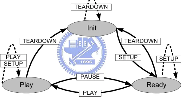
(33) - The client can automatically establish several simultaneous control sessions with different media servers. Media synchronization is performed at the transport level such as RTP. z. Separation of stream control and conference initiation - Stream control is detached from inviting a media server to a conference.. z. Suitable for professional applications - RTSP supports frame-level accuracy and allows remote digital editing.. z. Presentation description neutral - The protocol can convey the type of format to be used and does not require a particular presentation description which, however, must include at least one RTSP URI.. z. Proxy and firewall friendly - The protocol should be readily handled by both application and transport layer firewalls.. z. HTTP-friendly - As RTSP reuses HTTP concepts, the existing infrastructure can be utilized.. z. Appropriate server control - If a client can begin a stream, it must be able to stop a stream. Servers should not start streaming to clients if clients cannot stop the stream.. z. Transport negotiation - Before the client actually needs a media stream, it can negotiate the transport method.. z. Capability negotiation - The client will be informed via an easy mechanism if any basic feature is missing.. 2.2.3 RTSP States According to [3], media data flow and RTSP controls do not have to be sent via the same protocol. For instance, RTSP controls may run on TCP while the data may be transmitted via RTP. In fact, if there is no more RTSP control is issued by the client to the server, the data flow will still continue until the end of the presentation. In addition, RTSP requests during the lifetime of a media stream may be from different TCP connections.. -22-.
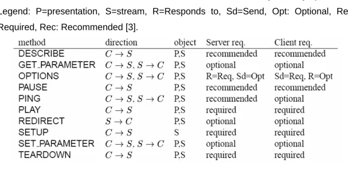
(34) Therefore, it is essential for both the server and the client to maintain “session state” to be able to associate RTSP requests and responses, respectively, with a stream. Referring to Figure 19, note that the rectangles represent methods which cause state changes if necessary, and the ellipses denote various states. The methods are described in the next section. Initially, the server (or client) is in “Init” state. After receiving “SETUP” request (response), it will transit to “Ready” state. Sequentially, it will receive “PLAY” request (response) so the streaming process can be started (“Playing” state). In addition, it the streaming process needs to be halted for some reason, it will receive “PAUSE” request (response) and go back to “Ready” state.. Figure 19 – RTSP State Machine. 2.2.4 Method Definitions A summary of available RTSP methods are listed in Table 1 [3]. Note that “direction” field indicates that in what direction the request should be sent. Also note that the field “object” specifies what objects they operate on. The field “Server req.” or “Client req.” states whether a method is required to be supported, optional, or recommended by the server or the client, respectively.. -23-.
(35) Table 1 – Overview of RTSP methods, their directions, and what objects they operate on. Legend: P=presentation, S=stream, R=Responds to, Sd=Send, Opt: Optional, Req: Required, Rec: Recommended [3].. z. DESCRIBE - It requests information about a presentation. For example [3], if the client wants the information about “rtsp://server.example.com/fizzle/foo” and it understands three types. of. description. formats,. “application/sdp”,. “application/mheg”, it can issue a request as: Request from client to server: DESCRIBE rtsp://server.example.com/fizzle/foo RTSP/1.0 CSeq:. 312. User-Agent: PhonyClient 1.2 Accept:. application/sdp, application/rtsl, application/mheg. Response from server to client: RTSP/1.0 200 OK CSeq:. 312. Date:. 23 Jan 1997 15:35:06 GMT. Server:. PhonyServer 1.0. Content-Type: application/sdp Content-Length: 376 v=0 o=mhandley 2890844526 2890842807 IN IP4 126.16.64.4 s=SDP Seminar i=A Seminar on the session description protocol. -24-. “application/rtsl”,. and.
(36) u=http://www.cs.ucl.ac.uk/staff/M.Handley/sdp.03.ps [email protected] (Mark Handley) c=IN IP4 224.2.17.12/127 t=2873397496 2873404696 a=recvonly m=audio 3456 RTP/AVP 0 m=video 2232 RTP/AVP 31 m=application 32416 UDP WB a=orient:portrait. The server then replies to the client with the information formatted in the type “application/sdp”. z. GET_PARAMETER - It inquires about the value of a parameter of a presentation. For example [3], if the server wants to know the values of “packets_received” and “jitter”, it can issue a request like the following: Request from server to client: GET_PARAMETER rtsp://example.com/fizzle/foo RTSP/1.0 CSeq:. 431. Content-Type: text/parameters Session: 12345678 Content-Length: 15 packets_received jitter. Response from client to server: RTSP/1.0 200 OK CSeq: 431 Content-Length: 46 Content-Type: text/parameters packets_received: 10 jitter: 0.3838. z. Options - It queries what methods are supported. For example [3]: Request from client to server:. -25-.
(37) OPTIONS * RTSP/1.0 CSeq:. 1. User-Agent: PhonyClient/1.2 Require: Proxy-Require: gzipped-messages Supported:. play-basic. Response from server to client: RTSP/1.0 200 OK. z. CSeq:. 1. Public:. DESCRIBE, SETUP, TEARDOWN, PLAY, PAUSE. Supported:. play-basic, implicit-play, gzipped-messages. Server:. PhonyServer/1.0. PAUSE - It halts the stream delivery of a presentation. For example [3]: Request from client to server: PAUSE rtsp://example.com/fizzle/foo RTSP/1.0 CSeq:. 834. Session: 12345678. Response from server to client: RTSP/1.0 200 OK. z. CSeq:. 834. Date:. 23 Jan 1997 15:35:06 GMT. Range:. npt=45.76-. PING - It may be used by both the server and the client to check each other’s liveness. For example [3], if the client wants to perform a single-hop liveness check, and the server responds with a positive result, then they should have a conversation like the following: Request from client to server: PING * RTSP/1.0 CSeq:. 123. Session: 12345678. -26-.
(38) Response from server to client: RTSP/1.0 200 OK CSeq:. 123. Session: 12345678. z. PLAY - It informs the server to start transmitting the requested data. For example [3], if the client only wants to enjoy the contents from 10 to 15 seconds, 20 to 25 seconds, and 30 seconds to the end, it can request the server as the following” Request from client to server: PLAY rtsp://audio.example.com/twister.en RTSP/1.0 CSeq:. 833. Session: 12345678 Range:. z. npt=10-15, npt=20-25, npt=30-. REDIRECT - It informs the client that it has to connect to another server. For example [3], if the server wants to redirect the traffic to a new server at a specific time, it can issue a request as the following: Request from server to client: REDIRECT rtsp://example.com/fizzle/foo RTSP/1.0 CSeq:. 732. Location: rtsp://bigserver.com:8001 Range:. npt=0- ;time=19960213T143205Z. Session: uZ3ci0K+Ld-M. z. SETUP - It specifies the transport mechanism for the streamed media. In the following example [3], the client wants to create an RTSP session containing the media, “rtsp://example.com/foo/bar/baz.rm”. and. accepts. two. types. of. transport. mechanisms: RTP/AVP/UDP received on client port 4588 and 4589, and RTP/AVP/TCP received on RTSP control channel. The sever answers with the response indicating that it prefers the first acceptable transport mechanism, that it. -27-.
(39) will send and receive RTP and RTCP via ports 6256 and 6257 respectively, and that it will use “2A3F93ED” as its SSRC. Request from client to server: SETUP. rtsp://example.com/foo/bar/baz.rm RTSP/1.0. CSeq:. 302. Transport: RTP/AVP/UDP;unicast;client_port=4588-4589, RTP/AVP/TCP;unicast;interleave=0-1. Response from server to client: RTSP/1.0 200 OK CSeq:. 302. Date:. 23 Jan 1997 15:35:06 GMT. Server:. PhonyServer 1.0. Session: 47112344 Transport: RTP/AVP;unicast;client_port=4588-4589; server_port=6256-6257;ssrc=2A3F93ED Accept-Ranges: NPT. z. SET_PARAMETER - Opposite to GET_PARAMETER, it sets the value of a parameter of a presentation. For example [3]: Request from client to server: SET_PARAMETER rtsp://example.com/fizzle/foo RTSP/1.0 CSeq: 421 Content-length: 20 Content-type: text/parameters barparam: barstuff. Response from server to client: RTSP/1.0 451 Parameter Not Understood CSeq: 421 Content-length: 10 Content-type: text/parameters barparam. z. TEARDOWN - It ends the session by stopping the stream delivery and freeing the resources. -28-.
(40) associated with the session. For example [3], if the client wants to end the session “rtsp://example.com/fizzle/foo” and the server grants the request, then they will have the following dialogue: Request from client to server: TEARDOWN rtsp://example.com/fizzle/foo RTSP/1.0 CSeq:. 892. Session: 12345678. Response from server to client: RTSP/1.0 200 OK CSeq:. 892. Server:. PhonyServer 1.0. 2.2.5 RTSP Status Codes In an RTSP response message corresponding to an RTSP request message, a numerical value named “status code” is included to give the result of the attempt to understand and satisfy the request. The first digit of the status code defines the class of the response, which is one of the followings: z. 1xx: Informational - It indicates that the request was received and the process continues.. z. 2xx: Success - It indicates that the request was successfully received, understood, and accepted.. z. 3rr: Redirection - It indicates that a further action must be performed so the request can be completed.. z. 4xx: Client Error - It indicates that the request contains syntax-error or cannot be accomplished.. z. 5xx: Server Error - It indicates that the server was not able to accomplish a valid request In Table 2, all available status codes and their usage with RTSP methods are listed.. -29-.
(41) Table 2 – Status codes and their usage with RTSP methods [3]. -30-.
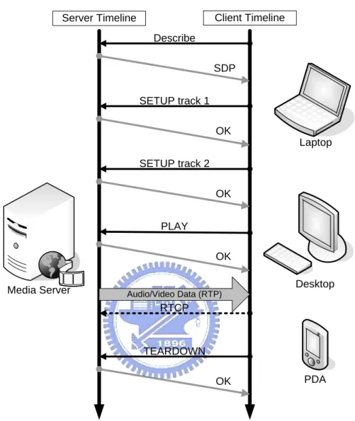
(42) 2.2.6 A Typical RTSP Unicast Session Example Client Timeline. Server Timeline Describe. SDP SETUP track 1 OK Laptop SETUP track 2 OK PLAY OK Media Server. Desktop Audio/Video Data (RTP). RTCP. TEARDOWN OK. PDA. Figure 20 – A typical RTSP unicast session example To summarize what have been described, an example is illustrated in Figure 20. As can be seen in the figure, a client (possibly a laptop, a desktop, or a PDA) wants to establish a connection with the media server in order to enjoy the media data. The first thing that the client has to do is to issue the request “DESCRIBE”, which asks the server for the information about the desired presentation. The server then replies with the information in accordance with Session Description Protocol (SDP) [4]. The client continues the action by issuing two “SETUP” requests to setup media data “track 1” and “track 2”. Since these two requests are valid and understood by the server, the server replies with “OK” to the client for both requests. After the setup procedure, the client. -31-.
(43) wants to start to enjoy the media data, so it proceeds with issuing “PLAY” request. The server agrees with the request by replying “OK”, and starts to stream the data via RTP channel. While transmitting the data, the client may simultaneously send reports about its reception statistics to the server via RTCP channel. In this way, the server can adjust its sending rate or change its transmission method when the RTP channel bandwidth alters. If the client wants to end the presentation, the client can issue a “TEARDOWN” request indicating the end of the session so the server can stop streaming the data.. 2.3 Introduction to Traffic Smoothing Algorithms Nowadays, numerous multimedia streaming applications like video-on-demand services, transmissions of recorded sports events or concerts, and distant learning depend on the efficient transfer of prerecorded video. Content servers usually store video on large and fast disks [5]-[7]. Clients such as PCs or set-top boxes, which have a limited-size playback buffer for storing temporary media data, can connect to content servers through IP networks. If high-quality videos are demanded, they will still require a huge amount of storage space and transmission bandwidth, even when they are already compressed by the most advanced encoding technologies such as MPEG-4 or H.264. These modern encoding schemes generate bitstreams of constant quality but variable-bit-rate (VBR) to avoid the quality degradation caused by constant-bit-rate (CBR) encoding methods [8] [9]. However, this VBR characteristic can cause significant burstiness on multiple time scales due to the natural variations within and between scenes, and the frame structure of the encoding algorithm [10], and as a result, complicates the allocation of disk, memory, and network resources [11]. Therefore, to be able to efficiently transmit constant-quality video, a technique that can smooth the burstiness is required. Intuitively, one may suggest that the server, network, and client could allocate resources based on the peak bitrate of the video, such over-reserving is exceedingly wasteful and depreciates the benefits of a constant-quality encoding. Fortunately, prerecorded video gives us an opportunity to reduce the variability of the network bandwidth requirements by transmitting frames to the client playback buffer in advance of each burst [12]. Based on a priori knowledge of the size of each frame, the. -32-.
(44) server can precompute a transmission plan that minimizes the bitrate variation and peak bitrate while avoiding both underflow and overflow of the client’s buffer. This technique is what we call “bandwidth smoothing”. Its benefits are the results of removing both short-term burstiness (e.g. large size difference between I-frames and P-frames) and medium term burstiness within and between scenes [13]. So far, in this field, six major smoothing algorithms have been proposed [13]-[18]. They have a common primary goal that is to reduce the peak rate of the stream, but however, they differ in what performance metrics they attempt to optimize. Hence, they can generate different transmission schedules of different performance properties, such as minimum number of rate changes in transmission, minimum variability of the bandwidth requirements, minimum utilization of the client buffer, minimum number of on–off segments in an on–off transmission model, change of transmission rates only at periodic intervals, and minimum general cost metrics through dynamic programming. For the implementation of the system concerned in this paper, since MVBA [13] achieves the goals of minimizing the peak transmission rate and the rate variability, and it is easier to implement than other algorithm, it will be selected among six smoothing algorisms to help the server transmit more efficiently.. 2.3.1 MVBA Goals The goals of MVBA, as claimed by the authors [13], are that given a fixed-size client buffer, a feasible transmission plan with: z. minimum variance of transmission rate. z. minimum peak transmission rate. z. and maximum lowest transmission rate. will be computed based on the a prior knowledge of frame sizes in the stored video. Note that a feasible transmission plan is a transmission plan that ensures the client buffer will never be drained nor overflowed. If the client buffer starves, then the presentation will be held up until more data are received. Conversely, if the client’s buffer is overloaded with data, then all the lately arriving data will be discarded until some spaces of the buffer become available.. -33-.
(45) Main Concepts z. Intuitively, because CBR transmission is the smoothest possible, during the computation of the transmission plan, CBR transmission segments should be extended as far as possible.. z. When the transmission rate must be increased or decreased to avoid starving or overflowing the client buffer, respectively, this rate change should be taken place as early as possible as to ensure the minimum rate variability.. Therefore, with MVBA, the transmission rate changes always occur at the earliest possible times for both rate increases and decreases. Thus, the generated transmission plan indeed gradually modifies the bandwidth requirement of the stream.. Concept Realization Up to now, only the goals of MVBA and the ideas behind MVBA have been introduced. How MVBA can be implemented in a real server system is still unmentioned and should be described now. In [13], the authors provide a complete pseudo code and ways that can generate an MVBA transmission schedule. The following notations are worth knowing [13]: z. Cmax: the maximum transmission rate at which the server can stream over a given interval, without overflowing the client buffer.. z. Cmin: the minimum transmission rate at which the server can stream over a given interval, without draining the client buffer. In fact, the resulted transmission schedule will consist of a series of CBR. transmission segments that might be Cmax or Cmax. Thus, to implement MVBA in a real server system, the system developer will just have to re-write the pseudo code in the used programming language such as C or C++. The resulted transmission plan will be the number of bytes that should be sent at each time instants. For example, for a video with the framerate of 25 frames per second, then the transmission plan probably will specify that at 0 ms, 1666.67 bytes should be transmitted, at 40 ms, 566.67 bytes should be transmitted, at 80 ms, another 333.33 bytes should be transmitted, and so on.. -34-.
(46) 2.3.2 Packet-based MVBA It is well known that in the current model of Internet, the data being transmitted from the source to the destination are not injected into the network bit by bit or byte by byte. Instead, in the real world, the data are sent as packets. Because along the path from the source to the destination, packets might pass by many different types of networks, each of which can support different maximum packet size (MTU), packets should not be made to be larger than the smallest MTU in these networks to avoid unnecessary fragmentations and reassembly. In addition to the maximum packet size, the size of each packet should be integers. A problem arises at this point. Recalling from previous section that at each time instant, the generated transmission plan will specify at each time instant how many bytes should be transmitted. The numbers of bytes specified may be of multiple decimal digits of precision or larger than the smallest MTU. To cope with this problem, a packet-based MVBA is needed and developed [24]. In short, the packet-based MVBA will generate a feasible transmission plan that follows the original MVBA generated plan the closest possible. The first step is to divide each video frame into fixed-size (say 1024 bytes) packets. For example, a frame of 3000 bytes will be segmented into two full 1024-byte packets and one 952-byte packet. Now instead of a series of frames available, a series of packets are on hand. Secondly, instead of just knowing the numbers of bytes that should be sent for different time instants as specified by the original MVBA, the accumulated number of bytes should also be computed. In other words, the total number of bytes that should be sent before and at each time instant is calculated. This new information will be referenced to derive the new packet-based plan. Now, it is time to derive the new transmission schedule. Essentially, for the time instant belonging to the Cmax segment in the original MVBA plan, the packet-based MVBA will take a number of packets from the series of available packets in order whose sizes sum up to be smaller or equal to the original accumulated number of bytes. This step ensures that the new schedule will approximate the old one the best and the client buffer will not be overflowed. Conversely, for the time instant belonging to the Cmin segment in the original MVBA plan, the packet-based MVBA will take a number of packets from the series of available packets in order whose sizes sum up to be equal to or larger the. -35-.
(47) original accumulated number of bytes. This step is to guarantee that the new schedule will follow the original one the closest possible and the client buffer will never starve. This short section only describes the packet-based MVBA in brief. For a more complete and in depth discussions about it, readers are encouraged to refer to [24].. -36-.
數據
![Figure 2 – RTP Header Format [2]](https://thumb-ap.123doks.com/thumbv2/9libinfo/8744887.204798/18.918.129.777.97.411/figure-rtp-header-format.webp)
![Figure 5 – Format of Receiver Report [2]](https://thumb-ap.123doks.com/thumbv2/9libinfo/8744887.204798/23.918.172.792.101.817/figure-format-receiver-report.webp)
+7
![Figure 7 – Format of Receiver Report [2]](https://thumb-ap.123doks.com/thumbv2/9libinfo/8744887.204798/26.918.158.787.101.994/figure-format-receiver-report.webp)
![Figure 18 - Format of APP [1]](https://thumb-ap.123doks.com/thumbv2/9libinfo/8744887.204798/30.918.171.792.796.1049/figure-format-of-app.webp)
相關文件
1、 網路管理與通信技術整合實務、機電控制、網拍多媒體行銷及物流從業人員
(A) IP (Internet Protocol) (B) ICMP (Internet Control Message Protocol) (C) ARP (Address Resolution Protocol) (D)SNMP (Simple Network Management Protocol)
(A)因為用 Terminal Services 可以不用安裝 ERP 的程式在 Client 端上可以減少 MIS 維護系 統的時間(B)沒有防毒軟體 (C)建置防火牆的系統 (D) APP-Server 與 DB
(A) NAT (Network Address Translation) (B) DHCP (Dynamic Host Configuration Protocol) (C) DNS (Domain Name Server) (D) ARP (Address Resolution
進而能自行分析、設計與裝配各 種控制電路,並能應用本班已符 合機電整合術科技能檢定的實習 設備進行實務上的實習。本課程 可習得習得氣壓-機構連結控制
Note that if the server-side system allows conflicting transaction instances to commit in an order different from their serializability order, then each client-side system must apply
This option is designed to provide students an understanding of the basic concepts network services and client-server communications, and the knowledge and skills
Time constrain - separation from the presentation Focus on students’ application and integration of their knowledge. (Set of questions for written report is used to subsidize
