Integration of Image Stabilizer with Video Codec for
Digital Video Cameras
Yu-Chun Peng, Hung-An Chang, Chia-Kai Liang,
Homer Chen
Graduate Institute of Communication Engineering National Taiwan University
Taipei, Taiwan
{b88901089, b89901049,r93942031}@ntu.edu.tw, [email protected]
Chang-Jung Kao
Quanta research instituteQuanta Computer Inc. Taipei, Taiwan [email protected]
Abstract— Electronic image stabilizer and video codec are two
important components of a digital video camera. Both require motion information of the captured image sequence to perform their respective tasks. Since motion estimation is a computationally intensive operation, we propose three schemes for integrating the electronic image stabilizer with the video codec. The technical issues involved in the integration are discussed, and the simulation results are shown to illustrate the effectiveness of the integration schemes.
I. INTRODUCTION
The movement of a video camera caused by hand jiggle introduces jerky image motion that is often annoying to human eyes. The problem can be solved by using an image stabilizer to compensate for the hand motion. As opposed to optical image stabilization which uses gyro-sensors to detect hand motion and shifts a corrective lens inside the lens system (or alternatively shifts the image sensor while keeping the lens fixed), electronic image stabilization detects the induced image motion based on the video data and shifts the image display window accordingly to compensate for the hand motion. For many digital video camera designs, electronic image stabilization is a cost effective solution and is the subject of discussion in this paper.
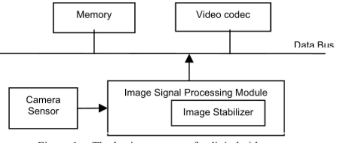
The basic structure of a digital video camera consists of an image signal processing (ISP) module, an imaging sensor, a video codec module, and a memory unit, all connected to a data bus as shown in Fig. 1. The image sequence captured by the camera sensor is processed frame by frame by the ISP module to handle color interpolation, color correction, white balance, image enhancement, etc. The image stabilizer (IS) is normally placed in the ISP module to compute the image motion and to stabilize the video sequence. Each stabilized video frame is then input to the video encoder. Both the video encoder and the image
stabilizer need to compute the image motion, but motion estimation is a computation intensive operation. Therefore, it makes sense from the system design point of view to integrate the motion estimation modules of these two components. The challenge is that the accuracy requirements of the two components are different. While the performance of the video encoder is highly sensitive to the accuracy of the estimated motion vectors, the image stabilizer requires a robust classification of motion vectors into camera/object motions. The granularity requirements of the motion field for these two components are different too. The video encoder requires one motion vector per block, whereas the image stabilizer simply needs one global motion vector per frame.
In this paper, we consider the integration of video codec with image stabilizer and address the issues stemming from the difference of the characteristics between the two components. Three integration schemes are proposed. In Scheme 1, the image stabilizer reduces the computational cost by confining the global motion estimation to within the background region determined by the video encoder. In Scheme 2, the image stabilizer performs block-based motion estimation and interpolation and feeds the data to the video encoder, which then performs sub-pixel refinement of the input motion vectors. In Scheme 3, the image stabilizer obtains the required motion information from the decoder.
The paper is organized as follows. In section 2, we briefly review the image stabilization system proposed in [1], which serves as the basis of the techniques described
This work was supported in part by the National Science Council of Taiwan under contract NSC93-2752-E-002-006-PAE.
Camera Sensor
Image Signal Processing Module Memory Video codec
Data Bus
Image Stabilizer
Figure 1. The basic structure of a digital video camera
4871
0-7803-8834-8/05/$20.00 ©2005 IEEE.
here. The integration of video codec with image stabilizer is described in Section 3, where a performance evaluation of coding and stabilization is also described. Finally, a summary is given in Section 4.
II. ELECTRONIC IMAGE STABILIZER
For videos captured by digital video cameras, hand jiggles or camera panning induces a global motion between successive image frames. Since the rate of hand jiggling is much higher than that of camera panning, the high-frequency image motion induced by hand jiggle can be removed by applying a low-pass filter to the detected global motion. The algorithm we developed [1] computes the motion vectors on a block basis. A clustering operation is then applied to the motion vectors, and the one that receives the highest votes is considered the global motion vector. This method works because in most cases the moving objects are relatively smaller than the other areas of the image. When this is not true, the object motion dominates the voting, and the low-pass filtering process results in a smoothed object motion, achieving an effect similar to image stabilization.
The architecture of our original image stabilizer [1] is shown in Fig. 2. The motion field between two successive frames is computed by block-based motion estimation as in most video coding systems. The resulting motion vectors are analyzed to determine the global motion vector. The global motion is then low-pass filtered to remove the effect of hand jiggle. Finally, the current frame is motion compensated by shifting the display window within the image area. The amount of shift is equal to the difference between the smoothed global motion and its original value. The stabilized image sequence is then input to the video encoder.
III. INTEGRATION OF IMAGE STABILIZER WITH VIDEO CODER
The digital image stabilization algorithm described in the previous section requires the computation of a global motion vector for each video frame. Most previous algorithms consider the global motion estimation as a separate process [3]-[5], [7]. Here, we take a different approach, the goal of which is to reduce the total computational cost by integrating the digital image stabilizer with the video codec. We consider three integration schemes and describe them in the following.
A. Scheme 1
In [1], we have found that the local motion vector that happens most frequently in a frame can be considered as the global motion of the frame. Such motion vectors usually belong to the background region of the image. To reduce the computational cost, we confine the computation of the global motion to within the background region. Unlike previous approaches that use predefined regions to search for the global motion [7], we determine the background region dynamically for each frame. This allows us to improve the accuracy of global motion estimation.
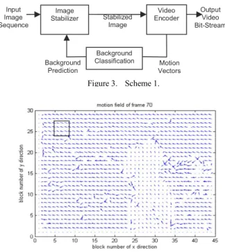
The block diagram of Scheme 1 is shown in Fig. 3, where the motion vectors computed by the video encoder are processed to obtain the global motion. Note that the input to the video encoder is a sequence of stabilized images. Thus the detected global motion represents the image motion that is induced by camera panning. Then the background region is formed by macroblocks with motion vectors equal (or close) to the global motion. A smaller region inside this background region is used to compute the global motion required for stabilizing the next video frame. That is, the computation of the global motion for image stabilization is confined to within the selected background region. In our simulation, a 64*64 block is chosen for the background prediction (shown in Fig. 4).
Figure 4. The predicted background region of frame 70. Therefore, the computational cost of motion estimation for the image stabilizer is reduced by a factor of (720*480)/ (64*64) =84.375. Fig. 5 shows that the global motion in x direction estimated by Scheme 1 is almost the same as that by the original image stabilizer described in [1]. The total absolute difference of global motion vectors over 300 frames between the integration scheme and the original scheme in [1] is 22 pixels, so the average error is 0.073 pixels. Input Image Sequence Global Motion Compensation Block-Based Motion Estimation Global Motion Estimation Global Motion Smoother Output Image Sequence
Figure 2. The block diagram of the image stabilizer.
Input Image Sequence Image Stabilizer Video Encoder Output Video Bit-Stream Stabilized Image Background Prediction Background Classification Motion Vectors Figure 3. Scheme 1.
4872
Note that Scheme 1 only uses the motion information generated by the video encoder. The additional operation for detecting the background region does not affect the video encoder.
Global motion in x direction
-20 -10 0 10 20 30 40 1 11 21 31 41 51 frame number global motion (pixel) Original scheme Scheme 1
Figure 5. Comparison of global motions estimated by Scheme 1 and the original scheme.
B. Scheme 2
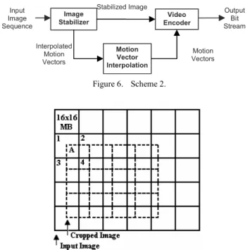
The block diagram of Scheme 2 is shown in Fig. 6. In Scheme 2, the image stabilizer computes the motion vectors of all the macroblocks. The resulting integer-pel motion vectors are input to the video encoder, which then performs sub-pixel refinement to obtain quarter-pel motion vectors.
The major challenging issue of this scheme is the misalignment of macroblocks before and after image stabilization. That is, due to the shifting of the display window, the macroblocks to be encoded by the video encoder are not aligned with those processed in the image stabilizer. As illustrated in Fig. 7, macroblock A contains part of the original macroblocks 1, 2, 3, and 4. The consequence of macroblock misalignment is that the motion vectors generated by the image stabilizer do not correspond to the new macroblocks. We solve the problem by motion interpolation. Denote the motion vector of macroblock A by
V and the motion vector of macroblock i by Vi, 1≤i≤4, we have: 4 1 1 ( ) * , 2 5 6 i i G i V w V V = =
∑
+ (1)where the weight wi is equal to the number of pixels
overlapped between macroblocks A and i and VG denotes
the global displacement vector.
For the investigation of coding efficiency, we implement Scheme 2 on an MPEG-4 video encoder. The encoder performs quarter-pel motion refinement on the interpolated motion vector. The resulting rate-distortion curve is labeled “Scheme 2” in Fig. 8. Compared with the original stabilization scheme described in [1], the PSNR of Scheme 2 drops about 0.1 dB at high bit rates and 0.8 dB at low bit rates.
Figure 7. Macroblock misalignment between the image stabilizer and the video encoder.
A full-search motion estimation is applied to the stabilized video sequence to compare the accuracy of motion vectors. We find that the interpolated motion vector is very close to the result of full-search motion estimation for most macroblocks. However, the accuracy of the interpolated motion vector drops for boundary blocks of moving objects. For such macroblocks, the refinement operation does not improve the coding efficiency further. To solve the problem, we examine the variance of the four motion vectors used for interpolation and perform the following step. If the variance is small, an additional refinement step using the small diamond search pattern [11] is applied to the interpolated motion vector. Otherwise, the video encoder performs a new motion estimation for the macroblock. With this additional step, the coding efficiency is improved, as shown in Fig. 8. Our simulation results indicate that only 13% of the motion vectors need to be re-computed. 30 32 34 36 38 40 500 1500 2500 3500 Bit Rate (Kbps) PSNR(dB) Original scheme Scheme 2 Improved Scheme 2
Figure 8. R-D perforamance of Scheme 2.
Input Image Sequence
Image
Stabilizer Encoder Video
Output Bit Stream Stabilized Image Motion Vectors Interpolated Motion Vectors Motion Vector Interpolation Figure 6. Scheme 2.
4873
Note that the ideas of this improved scheme can also be applied to Scheme 1 to speed up the motion estimation for the predicted background region.
C. Scheme 3
The block diagram of Scheme 3 is shown in Fig. 9, where the motion vectors carried in the video bit stream are used to determine the global camera motion. The method used for image stabilization is the same as the one described in [1]. This scheme is applied on the decoder side.
In this scheme, the intra macroblocks are excluded in the clustering process; only inter macroblocks are considered. In addition, to reduce the computational cost, sub-pixel motion data extracted from the bit stream are converted to integers. For each intra frame, an interpolation can be applied to obtain the global motion information from the previous and the next frames. However, this will result in an additional frame delay. In this scheme, we simply set the global motion of an intra frame to that of the previous frame. Likewise, a linear interpolation is applied to obtain the global motion for B frames.
Fig. 10 shows the result of the implementation of Scheme 3 using MPEG-4 codec. The global motion obtained by this scheme is very close to that estimated by the original image stabilizer [1]. The clustering and low-pass filtering operations in this scheme take less than one percentage of total decoding operation cycles. Unlike the previous schemes, the stabilizer here can be turned on or turned off while displaying.
Figure 9. Scheme 3. Global motion in x direction
-20 -10 0 10 20 30 40 1 11 21 31 41 51 frame number global motion (pixel) Original scheme Scheme 3
Figure 10. Comparsion of global motions estimated by Scheme 3 and the original scheme.
IV. SUMMARY
In this paper, we have described methods for the integration of image stabilizer with video codec for digital video cameras. Since the digital image stabilizer and the video codec share similar operations, the approaches proposed here can reduce the overall computational cost of a digital video camera while maintaining the performance of the two individual modules.
These methods are developed for various application scenarios. Scheme 1 is ideal for applications where legacy encoders are to be used, Scheme 2 is applicable to digital video cameras that allow a new video encoder design, and Scheme 3 is useful for applications where image stabilization is provided as a post-processing tool.
REFERENCES
[1] C.-K. Liang, Y.-C. Peng, H.-A. Chang, and Homer H. Chen, “The effect of digital image stabilization on coding performance,” Proc.
Int’l Symposium on Intelligent Multimedia, Video and Speech Processing, pp. 402-405, 2004.
[2] Y.-C. Peng, H.-A Chang, Homer H. Chen, and C.-J Kao, “Digital
Image Stabilization and Its Integration with Video Encoder,” Proc. IEEE Consumer Communications and Networking Conference,2005.
[3] K. Uomori, A. Morimura, H. Ishii, T. Sakaguchi, and Y. Kitamura, “Automatic image stabilizing system by full-digital signal processing,” IEEE Trans. Consumer Electron., vol. 36, no. 3, pp. 510-519, Aug. 1990.
[4] J. K. Paik, Y.C. Park, and S.W. Park, “An edge detection approach to digital image stabilization based on tri-state adaptive linear neurons,”
IEEE Trans. Consumer Electron., vol. 37, no. 3, pp. 521-530, Aug.
1991.
[5] J. K. Paik, Y.C. Park, and D. W. Kim, “An adaptive motion decision system for digital image stabilizer based on edge pattern matching,”
IEEE Trans. Consumer Electron., vol. 38, no. 3, pp. 607-616, Aug.
1992.
[6] S. Erturk, “Image sequence stabilization by low-pass filtering of interframe motion,” Proc. SPIE, Visual Communication and Image
Processing, vol. 4310, pp. 434-442, 2001.
[7] A. Engelsberg, and G. Schmidt, “A comparative review of digital image stabilising algorithms for mobile video communications,”
IEEE Trans. Consumer Electron., vol. 45, Issue 3, pp. 591 – 597,
Aug. 1999.
[8] S. Erturk, and M. K. Gullu, “Membership function adaptive fuzzy filter for image sequence stabilization,” IEEE Trans. Consumer
Electron., vol. 50, pp.1-7, Feb. 2004.
[9] Generic Coding of Audio-Visual Objects – Part 2 Visual, ISO/IEC 14496-2, 2001.
[10] Draft ITU-T Recommendation H.264 and Final Draft International
Standard of Joint Video Specification 14 496-10 Advanced Video Coding, May 2003.
[11] S. Zhu and K.-K. Ma, “A new diamond search algorithm for fast block-matching motion estimation,” IEEE Trans. Image Proc., vol. 9, pp. 287-290, Feb. 2000. Video Decoder Motion Vectors Image Stabilizer Input Video Bit-stream Decoded Image Sequence Stabilized Image Sequence
![Fig. 10 shows the result of the implementation of Scheme 3 using MPEG-4 codec. The global motion obtained by this scheme is very close to that estimated by the original image stabilizer [1]](https://thumb-ap.123doks.com/thumbv2/9libinfo/8681001.197173/4.918.86.432.628.983/result-implementation-scheme-motion-obtained-estimated-original-stabilizer.webp)
