A Surveillance Video System Based on Omni-directional and Network
Controlled Cameras
Yousuke Sato, Koji Hashimoto, Yoshitaka Shibata
Iwate Prefectural University, Japan
[email protected], [email protected], [email protected]
Abstract
In recent years, in the surveillance system which observes the behavior of human invasion to building or indoor, it is required not only to capture the high quality and wide area image, but also to automatically track to the specific suspicious person in real-time to reduce the number of the required surveillance cameras. While these installations have included a number of video streams, they have been also placed in contexts with limited personnel for monitoring. Using the suggested system, the location of the target motion objects in wide area with 360 degrees surround it can be detected and tracked by capturing high quality images in real-time.
1. Introduction
In surveillance system to keep safety and security for humans, it is required not only to capture the high quality and wide area image, but also to automatically track to the specific suspicious person in real-time to reduce the number of the required surveillance cameras.
With the conventional surveillance system which uses directional cameras, a number of one-directional cameras and their recording devices must be installed to cover wide area. This system leads to a complicated camera network system to monitor the images by operators and to record for a long time.
In this paper, we introduce a new surveillance system which is based on a combination of omni-directional camera[1] and networked Pan-Tilt-Zoom camera, so called PTZ camera. Using this system, the moving objects in wide area with 360 degree can be detected by the omni-directional camera and the coordinates of the position of the moving object is extracted. Then the relative pan and tilt angle for the PTZ camera can be calculated from the current position of the extracted the position of the moving object and the PTZ camera cane automatically controlled by
properly zooming to follow and identify the object operation.
In the followings, the system configuration is explained in section 2. Its architecture is precisely described in section 3. The camera work algorithm of the suggested system is explained in section 4. A prototype system for several applications and its functional and performance evaluations is shown in section 5. Finally conclusions of the current system and future works are summarized in section 6.
2. System Configuration
In our system, we call a combined system of an omni-directional camera and a PTZ camera and multiple directional microphones as Telegnosis system. In public, many different omni-directional cameras with various lens size from 1/3 to 3 inches in diameter, interfaces such as IEEE1394, USB2.0, camera link can be used depending on the applications, purpose and applied environments. Also the omni-directional camera can be reversely installed at upside down depending on the physical condition.
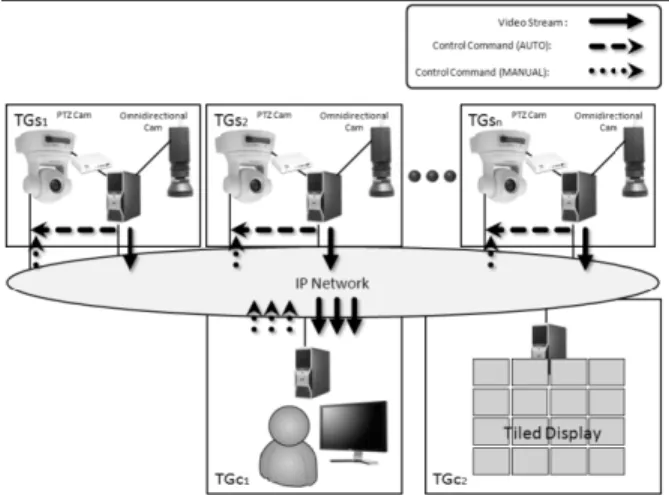
The system configuration is as shown in Figure 1 and consisted of multiple number of camera units TGs1~TGsn with camera server, omni-directional camera and PTZ camera and client TGc1. The omni-directional camera with PAL lenze is attached to DV, HDV or C-mounted USB camera and connected to the camera server through IEEE1394 or USB interfaces. On the other hand, the video output signal NTSC of the PTZ camera is converted by A/D converter to DV format and connected to the camera server through IEEE1394.
On the camera server, moving object detection function by which the location and the size of the moving object can be detected from the image and automatic motion tracking function by which the PTZ camera automatically can track to the detected moving object can be performed. The video images captured from the PTZ are sent to the client as a live video stream. At the same time, the captured images are automatically recorded and replayed on the client. The client can also interactively access to the server to replay, stop and forward the captured video images.
Furthermore, by introducing multiple numbers of camera units and servers, the whole captured images from various places can be received on the client at the same time and can be observed on the same display monitor or on the individual monitors on the client as a surveillance system. It is also possible to automatically display the particular video portion only when the moving detection events are generated.
On the other hand, the captured original omni-directional images can be directly sent and converted to the panorama images. By selecting the any positions on the panorama images and controlling the PTZ camera, the images from the PTZ camera equivalent to the selected positions can be displayed. In this case the automatic image tracking function is temporally released. Thus, the format conversion processing of omni-directional images to panorama images can be selectively performed based on CPU loads of the server or the client. Furthermore, the received video images from multiple locations can be output on the tiled display at the same time to attain the higher resolution and presence.
3. System Architecture
In the proposed system, three middleware functions are developed as function libraries. First, Midfield[2] is developed to transmit the omni-directional and PTZ vide images on IP network, record into files and control remotely the video stream. Second,
omni-directional middleware is developed to convert the omni-directional images to the equivalent panorama images. Third, PTZ middleware is developed to control the PTZ camera images. We call those system functions as Telegnosis system.
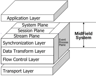
The system architecture of the proposed Telegnosis system is shown in Fig. 2 and constructed as a middleware on top of Midfield System which will be explained in session 3.1. This middleware includes two layers and three planes including interface layer, multimedia control layer and view control plain, event process plane and system management plane respectively.
Figure. 2 System Architecture
In interface layer, the information with user’s interactive operations from user to remote site is processed and transmitted to the under layer. The whole system state, multimedia stream state, development process state from the original ring image to panorama image control state of PTZ camera and it’s a set of static and dynamic parameters are managed in this interface layer. In multimedia control layer, actual development process from the omni-directional camera to panorama image, the computation of voice direction and PTZ camera control process by user’s operations and video stream creation and control functions are performed. In event processing plane, various events generated during a video session are detected and processed. In view control plane, the PTZ camera state, such as vertical and horizontal angles and zooming positions by pan, tilt and zoom operations is controlled and managed. In the system management plane, the session of teleconferencing by video and audio is maintained.
3.1. MidField System
As shown in Figure. 3, the MidField[3] system is located between the Telegnosis system and transport layer as a session layer. Midfield offers multimedia communication functions to the application layer. Furthermore, Midfield is divided into three layers and two planes.
Stream Plane
Flow Control Layer System Plane
Event Process Plane
Data Transform Layer Session Plane Synchronization Layer Application Layer Transport Layer MidField System
Figure 3 MidField System
Stream Plane is constructed by synchronization, data transform and media flow control layer, and performs multimedia stream processing. Session Plane performs management of communication sessions. System Plane monitors network traffic and CPU rate in the local host, and performs admission tests for QoS requirements from system user. Event Process Plane processes various events that are created in the system.
The system is able to construct intercommunication environment on computer networks dynamically according to the environment of users and QoS requirements from users.
3.2. Omni-directional Video Middleware
Omni-directional video middleware[3] performs the functions of Telegnosis system, including both interface and multimedia control layers and processes real-time image development from the original ringed image as shown in Figure 4a from omni-directional camera to panorama image as shown in Figure 4b.Figure. 4a Omni-Directional Ringed Image
Figure 4b Omni-Directional Panorama Image
Any pixel formats and various video interfaces including IEEE1394, USB 2.0 and camera link interfaces can be available according to applications and its environments. However, when the higher pixel resolution video format such as HDV with 1920x1080 and more is used, the processing load of the whole middleware system increases, the original frame rate cannot be maintained, and packet loss on the video stream and block noise occurs, eventually the QoS of the video stream may decrease. In order to avoid this problem, the video frame rate is controlled by sub-sampling the frame according to the CPU load of the sending host or the receiving host in system management plane.
4. Automatic Tracking Functions
First, the captured ringed images from omni-directional camera are converted to the equivalent panorama images. Then the moving object detection in the panorama images is examined. When the motion object is detected, the equivalent coordinates of top, left, right and bottom of the moving area are founded and the central coordinate of the moving area is calculated. Then the central coordinate for panorama camera system is converted to the PTZ camera system using the position parameters of both omni-directional camera and the PTZ camera which are calculated in advance. The calculated coordinate values is sent to the PTZ camera control middleware and the position of the
PTZ camera can be precisely controlled by pan and tilt functions.
4.1. Moving Object Detection Function
In order to extract the moving object from the video images, several method including background difference method, inter-frame difference method pixel density distribution method. Those methods include both advantage and disadvantage and there is no the best method. In our system, from computational simplicity, realtime processing and easy implementation points of view, we applied background difference method. The omni-directional ringed images are converted to the panorama images to extract the moving object. The moving object detection processing is developed as motion detection filter by directShow filter implemented on Microsoft Windows O.S. environment to process realtime video stream[4]. By imbedding this motion detection filter to the omni-directional image middleware, the center of the position of the moving area can be obtained as a pixel position of moving object.
On motion detection filter using background image model[5], moving pixels are extracted by subtracting the background image from the current frame. Since the background model images are influenced by fluctuation of brightness surround environment, the pixel values on past several frames are averaged and updated on every frame. As the number of the average frames are increased, the accuracy of the moving object extraction increases but waste computing resources. In our system, the average interval is controlled by moving rate of object to save computing power on the camera server. The moving pixels are decided based on the predetermined threshold which is adaptively applied depending on the size of the varied area and its deviation when the background difference computation is carried out.
When the moving pixels are extracted, the four corners, top, right, bottom and the central position of the moving area are found as shown in Fig. 5. From this central position of moving object, the pan and tilt angle are determined and zooming rate is determined by the width of the moving pixel area. By introducing multiple reference lines by multiple vertical and horizontal lines to interace whole panorama images and dividing the moving pixel area into the sub areas, multiple moving objects can be extracted.
Figure 5 Moving Pixels Area Extraction
4.2. Coordinate Conversion
When the PTZ camera is controlled for automatic tracking mode or manual operation mode, the coordinate of any pixel location on the panorama must be converted to the equivalent pan and tilt angle as shown in Fig. 6. The (Px, Py) on panorama pixel image is the pixel coordinate for automatic tracking mode and display window coordinate and the equivalent PTZ camera angle is calculated in the following equation[6][7].
PTZθ x = 360× Px/W+Ex (1)
PTZθ y = omniVRange× Py/H+Ey (2) omniVRange = |omniTop| + |omniBottom| (3) Where Ex and Ey are the gaps in the vertical and horizontal directions between the omni-direction camera and the PTZ camera and adjusted after installing at the place and omniTop and omniBottom are upper and lower limits of PTZ camera and H and W are height and width of the panorama image.
Figure 6 Panorama Image and PTZ Camera Angle
5. Performance Evaluation
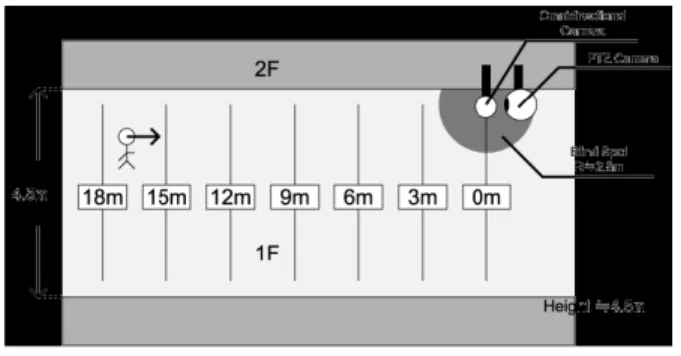
In order to evaluate performance of motion detection and tracking video methods by the proposed system, field experimentation was examined as shown in Fig. 7. In this experiment, both omni-directional camera and PTZ camera are installed at the ceiling, vertically 4.5m high from the floor. Horizontally the original point is set at the camera position. A testee walks at constant speeds from 20 m way from the original point. Then the motion detection start positions and frame out positions of the testee from PTZ camera were observed. Four different walking speeds were examined 5 times for each speed. Here, tracking start position means that motion detection starts to extract a moving object by omni-directional camera. The tracking limit means that the tracking speed of the PTZ camera exceeded its limited speed because of increase of the relative speed of moving object.
When the walking speed is 1 km/h, the moving object is hard to be detected because the pixel value deviation was under threshold value. Tracking detection function started at 6m and continued to the origin. On the other hand, when the walking speed is 7.2 Km, the moving object could be detected at 10 m but the ZTP camera could not be enough to track the moving object because of the pan and tilt speed limitation. On the other hand, when the walking speed is 3.6km/h and 5.4km/h which are average child and adult speed, sufficient motion tracking by PTZ camera could be attained.
Figure 7 Field Experimentation Table 1 Experimental Result Walking Speed Tracking Start Position Tracking limit Position 1 1km/h 6m 0m 2 3.6km/h 10m 1m 3 5.4km/h 12m 3m 4 7.2km/h 10m 9m
6. Conclusions
In this paper, we introduced a new surveillance system which is combination of omni-directional camera and PTZ control camera. While the omni-directional camera can detect the moving object in wide area with 360 degree, the PTZ camera can automatically track to moving object with proper high resolution. Then we explained its system configuration, architecture, motion detection and extraction and tracking methods. In order to verify our suggested system, a prototype system was constructed and evaluated its function and performance.
Through the performance evaluation, human motion with ordinal walking speed could be detected correctly. However, the motion detection for the human walking with slow speed could not be possible. This is because the improper threshold value to reduce the error due to the noise for omni-directional camera image. Thus, the the filtering function to reduce the error by omni-directional camera must be improved. Also the PTZ camera cannot track to the high speed moving object because of its response time limitation. This problem will be resolved by introducing multiple PTZ cameras and dividing the whole space into the sub domains to assigning those domains to the each camera.
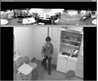
On the other hand, the screen shot images of indoor using the proposed surveillance system are shown in Fig. 8 and 9. Normally the camera captures the image of entrance of the room and can detect the person
coming into the room and track to the just bottom of the PTZ camera. Thus, the detection of the human movement could be possible when he is moving around the camera and the automatic tracking function could be effectively realized.
As future works, detection of multiple moving objects on the real street and motion tracking by multiple PTZ cameras will be developed.
Fig. 8a Automatic Tacking Image Function
Fig. 8b Automatic Tacking Image Function
7. Reference
[1] Yuya Miata, Koji Hashimoto and Yoshitaka Shibata, “A New TV Conference system with Flexible Middleware for Omni-directional Camera”, 8th International Workshop on
Network-Based Information System(NBiS’05), pp.84-88 22
Aug. 2005.
[2] Koji Hashimoto, Yoshitaka Shibata, “Design of A Middleware System for Flexible Intercommunication Environment”, IEEE Proc. on Advanced Information Networking and Applications, pp. 59-64, March 2003.
[3] Ryota Kobayashi, Yuya Maita, Koji Hashimoto, Yoshitaka Shibata, “Remote Healthcare Education Support System by Combination of Different Video Stream”, Proc. of
the 68th IPSJ Annual Conference, 6T-10, pp. 4-259~260,
March, 2006.
[4] Yukio Kubota, “Digital Video Dokuhon,” Ohme Co. 1995.
[5] Canon Co., Ltd., Sharp Co., Ltd., Sony Co., Ltd., Japan Victor Co., Ltd.,
http://web.canon.jp/pressrelease/2003/hdv.html(in Japanese), 2003.
[6] Ross Cutler, Yong Rui, Anoop Gupta, JJ Cadiz, “ Distributed Meetings: A Meeting Capture and Broadcasting System”, ACM Multimedia ’02, pp.1-6, December 2002. [7] Yasushi Yagi and Naokazu Yokoya, “Omni-directional Vision: Sensors,” Journal of Information Processing Society