0040-6090/97/$17.00q1997 Elsevier Science S.A. All rights reserved
Deposition of indium tin oxide films on polycarbonate substrates by
radio-frequency magnetron sputtering
Wen-Fa Wu
U, Bi-Shiou Chiou
Department of Electronics Engineering and Institute of Electronics, National Chiao Tung University, Hsinchu , Taiwan
Received 3 June 1996; accepted 3 September 1996
Abstract
Indium tin oxide (ITO) films have been deposited onto polycarbonate (PC) substrates by radio frequency (rf) magnetron sputtering. The influence of the oxygen content during sputtering on the film morphology, and the electrical and optical properties of the films have been investigated. Both the refractive index and the extinction coefficient decrease with increasing oxygen content. In this study, the figures of meritT10/Rshof the films are higher than those for low-temperature sputtered films reported in the literature.q1997 Elsevier Science S.A. Keywords: Coatings; Indium oxide; Optical properties; Sputtering
1. Introduction
Transparent conductive indium tin oxide (ITO) films are used extensively in a variety of electronics and optoelectron-ics applications because of their high transmission in the visiblerange,highinfraredreflection,andlowelectricalresis-tivity. The demand for ITO films with both low electrical resistivity and high transparency in the visible part of the solar spectrum has led to the development of various depo-sition techniques. Magnetron sputtering is considered to be one of the best methods for preparing high-quality ITO films. However, although ITO films with both high electrical con-ductivity and high visible transmittance have often been obtained, it is necessary to prepare them at high temperature (above 3508C) during deposition or post-deposition anneal-ing. Hence, in most of the work reported, ITO films were deposited onto various glass substrates that can withstand high-temperature annealing. Very few works have reported the deposition of ITO films at low-temperature on substrates such as plastics [1–4].
Transparent conductors on organic substrates have many applications, such as in plastic liquid crystal display devices, transparent electrostatic discharge and electromagneticinter-ference shielding materials, flexible electro-optical devices and unbreakable heat-reflecting mirrors [1,5]. Research is continuing in order to develop rf magnetron-sputtered ITO films on plastic substrates. In the previous work, ITO films
UCorresponding author.
were deposited onto acrylic substrates [1,2]. As the defor-mation temperature of acrylic is only 808C, a low substrate temperature and low rf power were maintained during sput-tering to prevent acrylic deformation, and a low deposition rate (;14 A˚ miny1at an rf power of 18 W) was obtained for film deposition [2].
In the present study, we employed polycarbonate as the substrate material. Polycarbonate has a higher deformation temperature (;1408C) than acrylic [6] and the film depo-sition process can be carried out at a higher rf power, so that a higher deposition rate could be expected [7]. The effect of oxygen content in the sputtering atmosphere on the micro-structure as well as the electrical and optical properties of the ITO films are investigated and discussed.
2. Experimental details
The ITO films were prepared by a commercial rf magne-tron sputtering system (IonTech, UK). The sputtering target was a 1-inch diameter hot-pressed oxide ceramic (90 wt% In2O3and 10 wt% SnO2, 99.99% purity) supplied by Cerac,
Inc., USA. The substrates employed were polycarbonate sheets (4.6=2.6=1.3 cm and 4.6=2.6=0.4 cm), which were degreased ultrasonically in a dilute detergent solution, rinsed ultrasonically in deionized water, and blown dry in N2
sub-W.-F. Wu, B.-S. Chiou / Thin Solid Films 298 (1997) 221–227
222
Fig. 2. SEM micrographs of ITO films;8000 A˚ thick deposited on glass
substrates at (a) 0%; (b) 1.5%; and (c) 3% oxygen. The arrows in (b) and (c) indicate the domain structure.
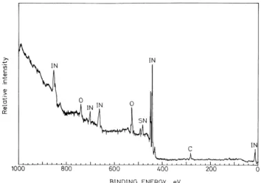
Fig. 1. Typical XPS survey spectrum of the ITO film deposited on a PC substrate.
strate was fixed directly above the target with a target-to-substrate distance of 6 cm. A parallel experiment on ITO films deposited onto glass substrates was also carried out for comparison. The vacuum chamber was pumped by a diffu-sion pump. High-purity Ar and O2were introduced through
a mass flow controller after the vacuum chamber was evac-uated to about 2.66=10y4Pa. The gas pressure was kept at 1 Pa and the sputtering power employed during deposition was 60 W.
The film thickness was measured with a stylus surface profiler. The sheet resistance of the samples was measured with a four-point probe and the resistivity of the film was calculated. An X-ray diffractometer was used to identify the crystalline phase of the films. A chemical binding energy analysis was performed using an X-ray photoemission spec-troscope (XPS, Perkin PHI-590AM SAM/1905 ESCA, Massachusetts, USA) with an Mg Ka X-ray source. The
microstructure of the films was analyzed using a scanning electron microscope (SEM, Hitachi S-4000, Japan) and a multimode scanning probe microscope (Digital Instruments, Inc., USA). The optical transmittance and reflectance of the films were measured with an ultraviolet–visible–near-infra-red spectrophotometer (Hitachi U-3410, Japan) and a Fourier transform infrared (FTIR) spectrophotometer.
3. Results and discussion
The deposition rate, defined as film thickness divided by the deposition time, is important in controlling the film thick-ness,especiallyforopticalcoatings.Inthisstudy,adeposition rate of;380 A˚ miny1was obtained at an rf power of 60 W and an argon pressure of 1 Pa. X-ray diffraction patterns of the as-deposited ITO films indicate that the films have the cubicbixbyitestructureofIn2O3[7–10].Fig. 1showstypical
XPS survey spectra of the ITO films produced in this study. The elements In, Sn, O and C are found in the spectra.
The influence of the oxygen partial pressure on the micro-structure of the film was investigated. Fig. 2 shows SEM
micrographs of ITO films;8000 A˚ thick deposited onto glass substrates at various oxygen percentages. As shown in Fig. 2, grainy surfaces can be observed for all specimens and the grain size tends to increase as the oxygen percentage increases. For the ITO films deposited at-1% oxygen, the ITO surface consists mostly of small grains. With further increases in oxygen content, the domain structure, as shown in Fig. 2(b,c), which is the gathering of small grains, is observed and the ITO films exhibit isolated domains ranging in size from;80 to;150 nm, embedded in the small grains on the surface. As shown in Fig. 2, the sizes and amounts of these domains increases with increasing oxygen percentage in the sputtering gas. Similar domain structures were also observed by Higuchi et al. [11].
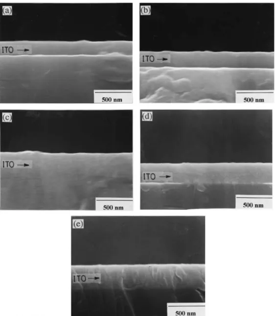
Fig. 3 shows cross sectional SEM micrographs of ITO films;2000 A˚ thick prepared on glass at various oxygen
Fig. 3. Cross sectional SEM micrographs of ITO films prepared on glass substrates at (a) 0%; (b) 1.5%; (c) 2.8%; (d) 3.5%; and (e) 4.0% oxygen.
Fig. 4. Cross sectional SEM micrograph of the ITO film prepared on glass substrates with 2% oxygen. Film thickness: 15 000 A˚.
percentages. A grainy structure appears and the typical columnar structure develops at an oxygen percentage
p)2.8%, whereas columnar structures are not observed for pF2.8%. A particle-like structure is occasionally observed
in the cross sectional SEM micrograph of the thick film (;15 000 A˚) prepared atpG2%, as shown in Fig. 4. It is
believed that film thickness affects the development of the
particle-like structure. However, the detailed mechanism is not yet understood and remains to be determined.
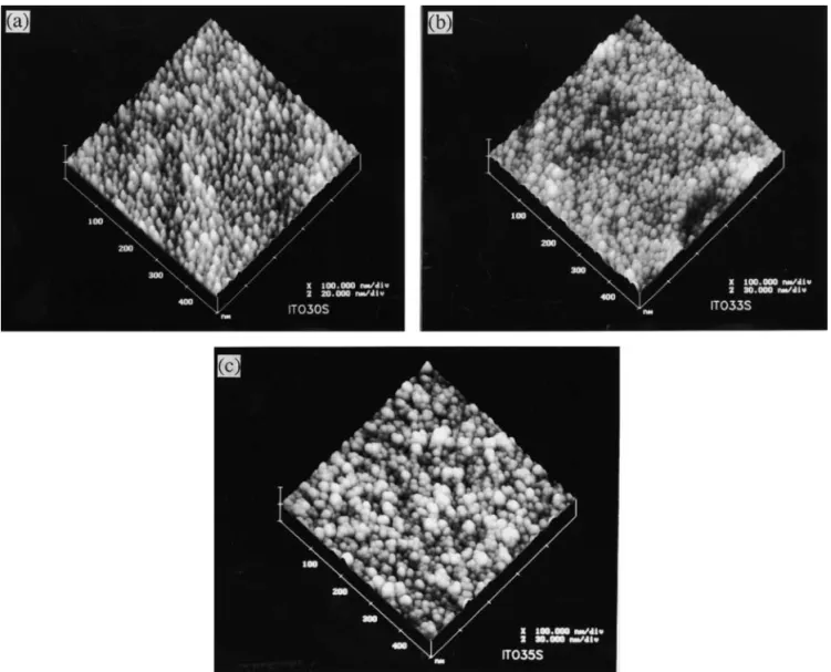
Because the plastic substrate deforms during an electron microscopic investigation [2], atomic force microscope (AFM) was used to investigate the microstructure of films deposited on PC substrates. Fig. 5 shows AFM micrographs of the ITO films;2000 A˚ thick prepared at various oxygen percentages. The size of the grainy columns increases from ;15 to;20 nm as the oxygen percentage increases from 0% to 4.6%. This implies an improvement in the degree of crystallinity, and is in good agreement with results for films deposited on glass substrates [4,10].
Fig. 6 shows that the resistivity of the films increases with increasing oxygen percentage. It has also been found that the resistivity of ITO films deposited on PC substrates is higher than that of films deposited on glass substrates. Dobrowolski et al. [3], in their work on ITO films prepared by an ion-assisted evaporation process, reported that films deposited onto different substrates had different resistivities. The resis-tivity of ITO films deposited on Mylar substrates was higher
W.-F. Wu, B.-S. Chiou / Thin Solid Films 298 (1997) 221–227
224
Fig. 5. AFM micrographs of ITO films prepared with (a) 0%; (b) 2.8%; (c) 4.6% oxygen.
Fig. 6. Resistivity of ITO films as a function of oxygen percentage. Film thickness;2500 A˚.
than that of films on glass substrates. They suggested thatthis could be due to the high temperature attained by the glass substrates during evaporation. The residual thermal stress,
ST, of the as-deposited film is given by
S sE (a ya )(T yT),T f f s D (1)
whereEfis the Young’s modulus for the film,afandasare
average thermal expansion coefficients of the film and sub-strate, respectively,TDis the film deposition temperatureand Tis the temperature after deposition. The thermal expansion
coefficients of In2O3, Corning 7059 glass, and PC are
7.2=10y6 [12], 4.6
=10y6 and 39
=10y6
8Cy1 [6], respectively, so that larger thermal stresses would develop when PC substrates are employed than those when glass sub-strates are employed. The difference in the residual thermal stresscouldbeonereasonforthedifferencesinfilmresistivity shown in Fig. 6.
Increases in resistivity with increasing oxygen pressure have also been reported by other researchers [13,14]. A par-allel experiment on ITO films deposited on glass substrates revealed that the carrier concentration decreases from ;2.3=1022to 1.3=1019cmy3as the percentage of oxygen in the sputtering gas increases from 0 to 4.5% [4,10], while the carrier mobility ranges from 11 to 21 cm2V-sy1in the oxygen percentage range of interest [4,10]. The incorpora-tion of oxygen leads to a decrease in oxygen vacancies in the
Fig. 10. Infrared reflectance as a function of wavelength for films depos-ited on PC substrates with various oxygen percentages. Film thickness
;2000 A˚.
Fig. 9. (a) Refractive indices and (b) extinction coefficients versus wave-length for as-deposited ITO films prepared with variousoxygenpercentages. Film thickness;1.1mm.
Fig. 8. Transmittance of ITO films prepared on PC substrates with various oxygen percentages. Film thickness;2000 A˚.
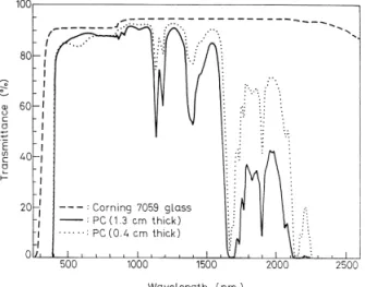
Fig. 7. Spectral characteristics of polycarbonate and glass substrates.
films, and hence to a fall in the charge carrier concentration, as follows:
y
$O2(g)qV0q2e9™O0. (2)
The high resistivity at high oxygen percentages is therefore attributed to the low charge carrier concentration of the film. Fig. 7 shows the spectral characteristics of polycarbonate and glass substrates. An average transmittance of;92% is obtained for Corning 7059 glass, but strong absorption is observed for PC substrates regardless of thickness. Hence, as the transmittance of films deposited on PCsubstratesismeas-ured, a bare PC substrate of the same thickness is used as a reference to eliminate the effects of strong absorption for PC substrates. The absorption observed at ;1400 nm and ;1900 nm is caused by adsorbed water vapor [15]. A dis-continuity of 1–2% is observed when the measuring wave-length range is switched from the visible to the near-infrared (850 nm), as the detector of the spectrophotometer is switched from a photomultiplier to a PbS cell [15].
Fig. 8 shows the transmittance of the as-deposited films prepared at various oxygen percentages. The transmittance of films prepared at 2% and 3% O2are higher than those of
films prepared at F1% O2. It is believed that the oxygen
deficiency in the ITO films prepared at low oxygen percent-ages contributes to the blackening of the ITO films [7,8,10]. The refractive index and extinction coefficient of the ITO films were calculated on the basis of Swanepoel’s method [8,16]. Fig. 9 shows the refractive indices and extinction coefficients versus wavelength for ITO films deposited at various oxygen percentages. As indicated in Fig. 9(a), the refractive indices of the ITO films decrease with increasing oxygen pressure. This decreasesuggeststhattheaverageden-sity of the film deposited at high oxygen pressure is less than that deposited at low oxygen pressure. This indicates that there are internal voids and surface irregularities in the film deposited at high oxygen pressures. These observations and previous SEM observations are in good agreement (see Fig. 2). Since the transmittance of the film is enhanced with
W.-F. Wu, B.-S. Chiou / Thin Solid Films 298 (1997) 221–227
226 Table 1
Comparison of low-temperature sputtered indium tin oxide films prepared by different researchers
Reference Substrate Substrate
temperature (8C) Sheet resistance, Rsh (V/square) Transmittance (%) (ls5500 A˚) Figure of merit (=10y3 Vy1) T10/Rshc T/Rsh
Chiou and Hsieh [1] Acrylic 50 19.06 74 2.58 38.6
Karasawa and Miyata [18] Glass Near room
temperature 55 84 3.18 15.2
Mukherjeea[19] Acrylic, glass,
polycarbonate – 20 81 6.08 40.5
Davis [20] Glass, quartz 30 300 70 0.09 2.33
Present workb Polycarbonate -50 27.3 90 12.7 32.9
aDid not specify the type of the substrate. bFilm prepared with 2% oxygen. cT10/R
shis the tenth power ofTdivided byRsh.
increasing oxygen pressure, the ITO films deposited at high oxygen pressure have smaller extinction coefficients, asindi-cated in Fig. 9(b).
Fig. 10 shows the IR reflectance as a function of wave-length for films deposited at various oxygen percentages.The IR reflectance of the ITO films decreases significantly athigh oxygen percentage. Frank et al. [17] showed that the IR reflectanceRcan be expressed by
4e0 0c 1
Rs1y , (3)
e Ndm
wherec0is the velocity of light,e0is the permittivity of free
space,eistheelectroniccharge,Nisthecarrierconcentration, d is the film thickness, and m is the mobility of the free
carriers. According to Eq. (3), the IR reflectance increases with the product of the carrier concentrationNand carrier
mobilitym. As discussed previously, the films deposited at
high oxygen percentages have higher resistivitiesandsmaller values of the productNmthan those deposited at low oxygen
percentages. Hence, the IR reflectance of the film decreases with increasing oxygen percentage, as observed.
For transparent conductor applications, it is essential to optimize the electrical and optical coating parameters. The figure of merit, which can be defined in several ways, is used to judge the performance of transparent conducting films. In Table 1, two common definitions of the figure of merit are adopted.ThefiguresofmeritT/RshoftheITOfilmsdeposited
onpolycarbonatesubstratesarecomparablewiththosedepos-ited on acrylic and glass substrates. In this study, the values ofT10/Rshfor the ITO films are higher than those for
low-temperature sputtered films reported in the literature.
4. Conclusions
1. ITO films were deposited on polycarbonate substrates by rf magnetron sputtering. The X-ray diffraction patterns indicatethattheas-depositedfilmhascubicbixbyitestructure of In2O3.
2. The grain sizes of the films increase as the oxygen content in the sputtering ambient increases. The addition of oxygen improves the crystallization of the film. The results of AFM investigations indicate that the size of grainycolumn of the film increases from;15 to;20 nm as the percentage of oxygen increases from 0 to 4.6%.
3. The resistivities of the films range between;6=10y4 and;2V-cm as the oxygen content is increased from 0 to 4.6%. The high resistivity at high oxygen percentageisattrib-uted to the low charge carrier concentration of the film.
4. Both the refractive index and the extinction coefficient of the film decreases as oxygen percentage increases.Inaddi-tion, the lower charge carrier concentration of the films pre-pared at higher oxygen percentage results in a decrease in the IR reflectance of the film.
5. The figures of meritT10/Rshfor the ITO films deposited
on polycarbonate substrates are higher than those for low-temperature sputtered films reported in the literature.
Acknowledgements
This work was supported by the Chung-Shan Institute of Science and Technology (contract No. CS 83-0210-D-009-001), and partly by the National Science Council of Taiwan (contract No. NSC 82-0417-E009-395).
References
[1] B.S. Chiou and S.T. Hsieh,Thin Solid Films,229(1993) 146.
[2] B.S. Chiou, S.T. Hsieh and W.F. Wu,J. Am. Ceram. Soc.,77(1994)
1740.
[3] J.A. Dobrowolski, F.C. Ho, D. Menagh, R. Simpson and A. Waldorf,
Appl. Opt.,26(1987) 5204.
[4] W.F. Wu,Rf Magnetron Sputtered ITO Films and ITO Films with Antireflective and Hard Coating, Ph.D. Thesis, National Chiao Tung
University, Hsinchu, June 1994.
[5] J.M. Margolis,Conductive Polymers and Plastics, Chapman & Hall,
[6] D.GrzegorczykandG.Feineman,Handbook of Plastics in Electronics,
Reston, Virginia, 1974.
[7] W.F. Wu and B.S. Chiou,Thin Solid Films,247(1994) 201.
[8] W.F. Wu and B.S. Chiou,Semicond. Sci. Technol.,9(1994) 1242.
[9] W.F. Wu and B.S. Chiou,Appl. Surf. Sci.,68(1993) 497.
[10] W.F. Wu and B.S. Chiou,Semicond. Sci. Technol.,11(1996) 196.
[11] M. Higuchi, M. Sawada and Y. Kuronuma,J. Electrochem. Soc.,140
(1993) 1773.
[12] Y. Shigesato, S. Takaki and T. Haranou,Appl. Surf. Sci.,48/49(1991)
269.
[13] K. Ichihara, N. Inoue and M. Okubo,Thin Solid Films,245(1994)
152.
[14] S. Honda, A. Tsujimoto, M. Watamori and K. Oura,Jpn. J. Appl. Phys.,33(1994) L1257.
[15] Instruction manual for Hitachi Model U-3410 recording spectrophotometer.
[16] R. Swanepoel,J. Phys. E: Sci. Instrum.,16(1983) 1214.
[17] G. Frank, E. Kauer and H. Ko¨stlin,Thin Solid Films,77(1981) 107.
[18] T. Karasawa and Y. Miyata,Thin Solid Films,223(1993) 135.
[19] A. Mukherjee,Vacuum,39(1989) 537.