The enhancement on optical attenuation by
a tunable non-smooth mirror
Cheng-Hsuan Lin, Wensyang Hsu*
Department of Mechanical Engineering, National Chiao-Tung University
1001 Ta Hsueh Road, Hsinchu, Taiwan, 30010, Republic of China
ABSTRACT
Here the attenuation effect of a variable optical attenuator (VOA) with a tunable non-smooth mirror is investigated experimentally and analytically. The working principle of this VOA is based on the non-uniform deformation shape of a mirror membrane by thermally driven bimorph actuators. Before deformation, the surface roughness of Rymax and insertion loss of the mirror membrane are calibrated as 15 nm and 0.53 dB, respectively. The attenuation tests on smooth and non-smooth concave mirrors are also conducted. In simulation, the attenuation effects by various smooth spherical shapes are modeled by ray tracing method and Gaussian beam theory, and the simulation results are compared with experimental data. It is found that the attenuation behaviors between simulation and calibration results on smooth, spherical concave mirrors have good agreement. Also, by comparing the experimental results from smooth and non-smooth concave mirrors, the attenuation is found to be enhanced by the non-non-smooth mirror surface evidently. The maximum dynamic range of attenuation is found to be more than 40 dB at input voltage of 46 V.
K e y wor ds: e nha nc e me nt a t t e n ua t i o n, no n- s m o ot h mi r ror, t r a ns mi ssi on ma t r i x, opt i c a l c ompone nt , M E M S
1. INTRODUCTION
Lately, the optical attenuator has attracted lots of attentions in MEMS for its applications in optical communication. One of the popular approaches on MEMS optical attenuators is based on the sliding mirror mechanisms 1-3. This type of attenuators can provide the optical attenuation higher than 57 dB 1. However, the insertion loss is also higher than 1.5 dB 1. Another approach is based on a tilting mirror 4, 5 or mechanical antireflection switch (MARS) 6 by modulating the light transmitted through the optical components. Liquid crystal is also used to attenuate the light power without moving parts 7, which can provide faster response time than the sliding mirror type. The dynamic range of attenuation was less than 30 dB 6.
In this work, a new approach is proposed to attenuate the light power by using a tunable non-smooth concave mirror to act as a variable optical attenuator (VOA). The smooth flat mirror surface can provide a low insertion loss before deformation. Furthermore, the non-smooth mirror surface after deformation is expected to enhance the optical attenuation under a similar mirror curvature.
2. CONCEPT DESIGN OF THE VOA WITH A TUNABLE NON-SMOOTH MIRROR MEMBRANE
Figure 1 shows the side view of the proposed VOA with a tunable mirror membrane by thermally driven bimorph actuators. This VOA is fabricated by combining surface micromachining and back-side etching techniques, where the back-side of membrane is sputtered with gold to act as the mirror surface 8.
*
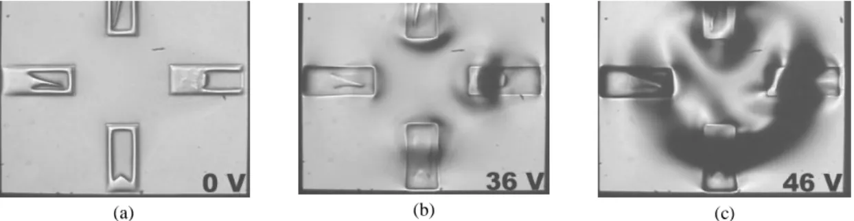
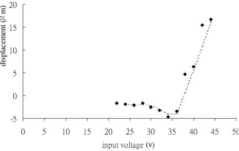
Figure 2(a) shows the fabrication results of the flat reflecting mirror made of gold before deformation, where the SiN layer with bimorph actuators are underneath. The surface roughness, Rymax and Ra, are calibrated as 15 nm and 3 nm, respectively. When the bimorph actuators are electrically heated, the mirror becomes a non-smooth concave shape under different input voltages, as shown in Figure 2(b) and Figure 2(c). The deflections at the central mirror membrane are also calibrated under different input voltages, as shown in Figure 3, by a Laser Confocal Displacement Meter (KEYENCE Co., LT 8110). Four bimorph beams are applied with the same voltage simultaneously. When the input voltage is above 22 V, the mirror membrane starts to deflect, and evident deformation starts from 36 V.
Figure 1. Cross-section view of a VOA with a tunable non-smooth mirror.
(a) (b) (c)
Figure 2. Photos of deformed mirror membrane and four embedded bimorph beams at different input voltages. (a) A flat mirror at 0 V; (b) A concave shape mirror at 36 V; (c) A non-smooth concave shape mirror at 46 V.
Si
bimorph actuator
reflecting mirror
ˀˈ ˃ ˈ ˄˃ ˄ˈ ˅˃ ˃ ˈ ˄˃ ˄ˈ ˅˃ ˅ˈ ˆ˃ ˆˈ ˇ˃ ˇˈ ˈ˃ ˼́̃̈̇ʳ̉̂˿̇˴˺˸ʳ(vʼ di spl ac em ent (Ӵ m)
Figure 3. Deflections at the central of the mirror membrane.
3. SIMULATION OF A SMOOTH SPHERICAL MIRROR
In order to verify the enhancement effect of the tunable non-smooth mirror, the simulation on a smooth spherical mirror is performed first. The relationship of light rays at different locations between two optical fibers can be modeled by ray tracing method, whose dimensions with hundreds of micrometer are much larger than the wavelength of 1.55 µm. Also, according to the Gaussian beams theory, the width of light beam at crose section area of optical fiber propagates through optical components can also be modeled for a smooth spherical mirror 9, 10.
The optical paths between two sides of an optical component are modeled by the transmission matrix, T, as:
=
1 1 2 2θ
θ
r
T
r
, (1)where the indexes, 1 and 2, mean two sides of an optical component at light axis, and r1, r2, θ1, and θ2 represent the location and direction of light rays.
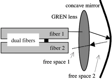
As shown in Figure 4, the optical path starts from the optical fiber 1, passes through free space 1, GREN lens, free space 2, reflecting mirror, then reflects back to optical fiber 2 in reverse way. The GREN lens and two single mode optical fibers together are also called the dual fiber collimator. The transmission matrices for free space 1, free space 2, and reflecting mirror are denoted by Tf1, Tf2, and Tm, respectively, as expressed in Eq. (2). Furthermore, Tg is the transmission matrix of GRIN lens.
dual fibers
concave mirror
GREN lens
free space 1
free space 2
fiber 1
fiber 2
dual fibers
concave mirror
GREN lens
free space 1
free space 2
fiber 1
fiber 2
Figure 4. Schematic diagram of the modeling optical attenuator with the smooth concave mirror.
−
≡
≡
≡
1
2
0
1
1
0
1
1
0
1
2 2 1 1 m m f fR
T
d
T
d
T
(2)The d1 and d2 represent the distance of free space 1 and 2, respectively. The Rm represents the radius curvature of concave mirror. The transmission matrix of the system, T, represents the light beam passing through a sequence of optical components from optical fiber 1 to optical fiber 2, and can be expressed as Eq. (3).
1 2 2 1 g f m f g f f
T
T
T
T
T
T
T
T
=
(3)The attenuation from optical fiber 1 to optical fiber 2 is expressed in Eq. (4), where the w1 and w2 represent the width of light beam at crose section of fiber 1 and fiber 2, respectively. The relationship of the w1 and w2 can also be computed by the transmission matrix of system, T 9.
2 2 2 2 1 2 1
2
log
20
+
−
=
w
w
w
w
Loss
(4)beam, then the parallel light beam can be emitted into the mirror and be reflected to the power meter. The insertion loss of the dual fiber collimator is given as 0.21 dB by the manufacturer.
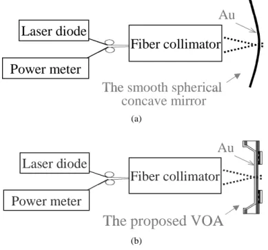
In attenuation test, a series of smooth spherical concave mirrors with different radius curvature are tested first, as shown in Figure 5(a). Then, the attenuations by the tunable non-smooth mirror at different input voltages are calibrated, as shown in Figure 5(b).
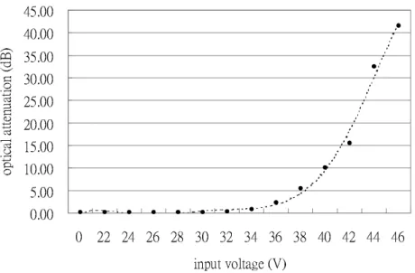
Figure 6 shows the dynamical optical attenuation of the proposed tunable non-smooth mirror under different input voltages. The input voltage in testing is increased from 0 V to 46 V gradually. Each data point represents the average of ten different tests in steady state with the same sample. The attenuation effect can be observed when input voltage is above 34 V. The 30 dB attenuation, which is the typical requirement on attenuators, can be achieved around 44 V. The maximum dynamic range is higher than 40 dB when the input voltage is 46 V.
Laser diode
Power meter
Fiber collimator
Au
The smooth spherical
concave mirror
Laser diode
Power meter
Fiber collimator
Au
The smooth spherical
concave mirror
(a)Laser diode
Power meter
Fiber collimator
Au
The proposed VOA
Laser diode
Power meter
Fiber collimator
Au
The proposed VOA
(b)Figure 5. The schematic diagram of experimental setup in attenuation measurement. (a) A series of smooth spherical concave mirrors with different radius curvature; (b) A reflecting mirror of the proposed VOA.
˃ˁ˃˃ ˈˁ˃˃ ˄˃ˁ˃˃ ˄ˈˁ˃˃ ˅˃ˁ˃˃ ˅ˈˁ˃˃ ˆ˃ˁ˃˃ ˆˈˁ˃˃ ˇ˃ˁ˃˃ ˇˈˁ˃˃ ˃ ˅˅ ˅ˇ ˅ˉ ˅ˋ ˆ˃ ˆ˅ ˆˇ ˆˉ ˆˋ ˇ˃ ˇ˅ ˇˇ ˇˉ ˼́̃̈̇ʳ̉̂˿̇˴˺˸ʳʻ˩ʼ ̂̃ ̇˼˶ ˴˿ ʳ˴ ̇̇˸ ́̈ ˴̇ ˼̂ ́ʳ ʻ˷ ˕ʼ
Figure 6. Calibrated attenuation at different input voltages of the proposed VOA with a tunable non-smooth mirror.
5. COMPARISON OF SIMULATION AND CALIBRATION RESULTS
In order to simulate the attenuation effect by the smooth spherical mirrors, the parameters in transmission matrices of Eq. (2) needs to be determined first. By direct measurement, d1 and d2 are found to be 0.242 mm and 0.25 mm, respectively. The range of Rm is from 1 mm to 200 mm. Therefore, the Tf1, Tf2, and Tm, can be determined, and Tg is given by the manufacturer. The w1 at the cross section of a single mode optical fiber is 5 µm.
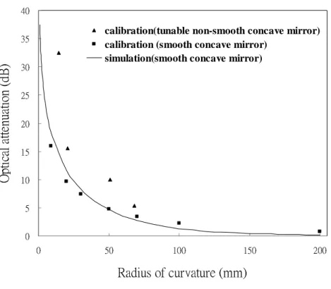
The simulation and experimental results of smooth spherical concave mirrors with different radii of curvature are both shown in Figure 7 with good agreement, where the black line represents the simulation results and the square mark, represents the calibrated results.
If the reflecting mirror of the proposed VOA is assumed to deform in a spherical concave shape, the corresponding radius of curvature can be calculated by calibrating the relative displacements between the central membrane and the end of bimorph actuators, since the horizontal distance between central point of the membrane and the end of the bimorph actuators are known. Then the attenuations by the tunable non-smooth mirror membrane can be expressed in terms of the radius of curvature, also shown in Figure 7, which is denoted with the triangle mark.
˃ ˈ ˄˃ ˄ˈ ˅˃ ˅ˈ ˆ˃ ˆˈ ˇ˃ ˃ ˈ˃ ˄˃˃ ˄ˈ˃ ˅˃˃
˥˴˷˼̈̆ʳ̂˹ʳ˶̈̅̉˴̇̈̅˸ʳʻ̀̀ʼ
ˢ
̃̇
˼˶
˴˿
ʳ˴
̇̇˸
́̈
˴̇
˼̂
́ʳ
ʻ˷
˕ʼ
calibration(tunable non-smooth concave mirror) calibration (smooth concave mirror)
simulation(smooth concave mirror)
Figure 7. Calibrated and simulate attenuation effects different mirror curvature.
It is found that, for example, when the radius of curvature of mirror is 50 mm, the non-smooth mirror can provide about 5 dB more attenuation than the smooth one can achieve. It indicates that the attenuation effect can be enhanced by non-smooth mirror surface of this VOA design.
6. SUMMARY AND CONCLUSION
A VOA with a tunable non-smooth mirror is proposed, fabricated and tested here. From experimental results, the SiN membrane coated with Cr/Au is found to be flat enough to provide insertion loss of 0.53 dB before deformation. The thermal bimorph membrane actuator is shown to be able to deform the mirror up to 16 µm at the central mirror membrane at 44 V, even the deformed membrane is not smooth. In simulation, the attenuation by smooth spherical mirrors with different curvatures are computed. Furthermore, a series of smooth spherical concave mirrors with different radii of curvature are also tested to verify the above simulation results. By comparing the experimental data between smooth and non-smooth mirror surfaces, it also verifies that the attenuation can be enhanced by non-smooth effect. The dynamic range of the proposed attenuator is more than 40 dB at input voltage of 46 V.
7. ACKNOWLEDGEMENTS
Authors deeply appreciate Mr. Shih-Yi Wen for helpful discussion in simulation and testing. The realization of this work was supported by Semiconductor Research Center of National Chiao Tung University, the measurement of this work was supported by Opto-Electronics & Systems Laboratory of Industrial Technology Research Institute. This project was supported by the Ministry of Education of the Republic of China for promoting academic excellence of universities in “Photonic Science and Technology for Tera Era” under grant number 89-E-FA06-1-4.
8. REFERENCES
1. C, Marxer, P. Griss and N. F. de Rooij, “A Variable Optical Attenuator Based on Silicon Micromechanics”, IEEE photonics technology letters, Vol. 11, No. 2, pp.233-235, Feb., 1999.
2. C. R. Giles, V. Aksyuk, B. Barber, R. Ruel, L. Stulz and D. Bishop, “A Silicon MEMS Optical Switch Attenuator and Its Use in Lightwave Subsystems”, IEEE J. of selected topic in quantum electronics, Vol. 5, No. 1, pp.18-25, Jan./Fab, 1999.
3. R. Wood, V. Dhuler, and E. Hill, “A MEMS Variable Optical Attenuator”, IEEE Optical MEMS, pp. 121-122, 2000.
4. B. M. Andersen, S. Fairchild, and N. Thorsten, “MEMS Variable Optical Attenuator for DWDM Optical Amplifiers”, Optical fiber communication conference, Vol. 2, pp.260-262, 2000.
5. S. Sumriddetchkajorn, and N. A. Riza, “Micromachine-based Fault-Tolerant High Resolution High-Speed Programmable Fiber-Optic Attenuator”, Optical fiber communication conference, Vol. 3, pp.240-242, 2000. 6. J. E. Ford, J. A. Walker, D. S. Greywall, and K. W. Goossen, “Micromechanical Fiber-Optic Attenuator with 3µs
Response”, J. of lightwave technology, Vol. 16, No. 9, Sep., 1998.
7. H. Katsuhiko, W. Masato, and A. Chikara, “Optical-Fiber Variable-Attenuator Arrays Using Polymer-Network Liquid Crystal” IEEE Photonics Technology Letters, Vol. 13, No. 5, May, 2001.
8. C. H. Lin, S-Y Wen, C. Hu, H-W Lee, W. Hsu, “A Variable Optical Attenuator with Tunable Mirror Curvature”, ASME IMECE’02, New Orleans, Louisiana, USA, 2002.
9. Saleh Bahaa E. A. and Teich Malvin Carl, Fundamentals of photonics, JOHN WILEY & SONS, INC., 1991. 10. Verdeyen Joseph T., Laser Electronics, Prentice Hall, INC, 2000.