ELSEVIER
Printed in Northern Ireland. All rights reserved 0143-8166/95/$9.50 0143-8166(95)ooo13-5
A Hybrid Neural Network for Image Classification
K. Y. Hsu & S. H. Lin
Institute of Electra-Optical Engineering, National Chiao Tung University, Hsinchu, Taiwan, R.O.C.
&
T. C. Hsieh
Department of Electra-Physics, National Chiao Tung University, Hsinchu, Taiwan, R.O.C.
ABSTRACT
Principles of the photorefractive perceptron learning algorithm are described. The influences of the finite response time and hologram erasure of the photorefractive gratings on the convergence property of the photorefractive perceptron learning are discussed. A novel neural network which could resolve these constraints is presented. It is a hybrid system which utilizes the photorefractive holographic gratings to imple- ment the inner product between the input image and the interconnection matrix. A personal computer is used for storing the interconnection matrix and the updating procedure, and it also functions as a feedback means during the learning phase. After training the weight vectors are recorded in the volume hologram of an optical processor. This novel method combines the advantages of the massive parallelism of optical systems and the programmability of electronic computers. Experimental results of image classification are presented. It shows that the system cduld correctly classify the input patterns into one of the two groups afrer training on four examples in each group during successive iterations. The system has been extended to perform multi-category image classification.
1 INTRODUCTION
In recent years neural networks have been extensively studied.‘,’ The motivation of this research is stimulated by the interest to look for a computing architecture which shares some characteristics of the biolog-
ical system such that it could address problems such as pattern
K. Y. Hsu, S. H. Lin, T. C. Hsieh
recognition that animals do well but current computers do not. The
most interesting property of neural networks is the capability of
learning. During the learning stage, the network is exposed to a proper
set of training samples with an appropriate training algorithm. The
networks then adjust their interconnections until each input produces
the desired response. After the training is complete the network could
be used for information processing such as pattern classification,
associative memory and speech recognition. Several types of neural
networks have been proposed and demonstrated successfully.%-’
On the other hand, optics has been considered as one of the
technologies for the implementation of neural networks because the
parallel nature of optical systems matches well with that of the neural
network. Furthermore, recent progress in photorefractive holography
provides a very promising technique for realizing the dynamic intercon-
nections in the neural network. Several optical systems have been
proposed and demonstrated. C10 In these systems, the learning behavior of the neural network is simulated by updating the holographic dynamic gratings stored in the photorefractive crystal, which responds in real
time to the input light intensity distribution. Several problems are
encountered in the implementation of photorefractive perceptron
networks. First, the dynamic characteristics of the photorefractive
grating imply that the stored interconnections are, in addition to being updated by the particular patterns, subject to erasure problems during the training cycles. This results in a restriction to the period of exposure
time in the learning process. The mathematical derivation of condi-
tional convergence of this type of neural network was discussed
previously.1**‘2 It was shown that the sufficient condition for the learning iteration to converge is that the exposure time in each learning iteration
be much less than the time constant of the photorefractive crystal.
Otherwise, the learning may not converge to a solution. Furthermore, after the training the interconnection weights of the network, which are stored in the photorefractive crystal, will decay during the read-out
illumination. Finally, the photorefractive hologram will be erased
completely. Therefore, it is difficult to use the same crystal volume for
training for the recognition of a new category of images. In other
words, the system is difficult to extent to a multi-class case.
In this paper, we present a hybrid method for implementing the
perceptron algorithm. It can combine the merits of parallelism of optics and the programmability and non-volatile memory of electronics. In the training stage, the optical part performs the inner product operation of
the perceptron. The learning algorithm and the interconnection weights
time and hologram erasure problems on learning behavior in the pure
photorefractive network can be avoided. Furthermore, the interconnec-
tion is easy to copy and can be used for post-processing. After training, the final weights are transformed into a volume holographic memory in the photorefractive crystal by the angular multiplexing technique. This holographic memory can then be used for optical image classification. In Section 2, principles of the photorefractive optical perceptron are first reviewed. The problem of hologram erasure and its effect on the
convergence property of the network are addressed. In Section 3, the
hybrid system is presented. The inner product is performed optically
using a thin photorefractive crystal plate. On the other hand, the
learning algorithm and the interconnection weights are stored in a
personal computer. The technique of using a liquid crystal television
(LCTV) for performing the bipolar inner product is described. In
Section 4, experimental results on using the system for real-time
two-category pattern classification are presented. Extension of the
system for multi-class image classification is also described. Finally, in Section 5, conclusions are presented.
2 THE PHOTOREFRACTIVE NEURAL NETWORK
In this paper we consider a single layer perceptron network.13 The
network consists of N-input units, an N-dimensional interconnection
weight vector w and one output neuron. Typically, the network is
trained to classify a set of training patterns {x,, x2, . . . , x,} into two classes Cl and C2, depending on whether the value of the inner product Iw . x,,j is greater or smaller than the threshold value 8. During the
learning stage, the network is trained according to the learning
algorithm to find an appropriate w for the desired classification.
Several types of photorefractive (PR) neural networks have been
proposed and demonstrated for the .implementation of the perceptron
learning algorithm. In these systems the interconnection weights are
recorded as holographic gratings stored in PR crystals such as LiNb03 and BaTiO,. The PR crystals respond in real-time to the input light intensity distribution, with response time in the range of several tens of milliseconds to a few minutes under an illumination intensity approxim- ately in the range of Watts per cm 2. This finite response property provides the capability for updating the interconnection weights during the learning iterations. The quantity of the weight change for each step can be expressed as a(p)[l - e-“‘lx(p), where r is the writing time constant of the crystal, t is the exposure time for each pattern, cr(p) is
170 K. Y. Hsu, S. H. Lin, T. C. Hsieh
the updating or error signal and x(p) is the input pattern at the pth
iteration. Since all the holographic gratings are stored in the same
volume of the photorefractive crystal, the previously recorded gratings are also illuminated and decayed when an exposure is made to either add or subtract weights to the crystal. Thus, the updating rule of the
photorefractive perceptron can be described by the following
expression:
w(p + 1) = w(P)e- In(p)lrir + a(p)[l - e-“‘lx(p), (1)
where w(p) is the interconnection weight vector at the pth iteration and the updating signal LX(~) is expressed by:
1
0 if x(p) is correctly classified
a(p) = 1 if x(p) E Cl, but /w(p) .x(p)] < 0 (2)
-1 if x(p) E C2, but /w(p) .x(p)1 > 13
Note that, in general, the decay time constant for erasing photorefrac-
tive holograms and the writing time constant for recording the
holograms may be different. The convergence behavior of this case has been shown in Ref. 12. The crystal that we used for the training experiments was BaTiO,, of which the writing and decay time constants
are almost equal. Hence, for a simpler illustration, the two time
constants are assumed to be equal in eqn (1). Also note that, in the above expression, the absolute value of the inner product is utilized for
comparison with the threshold. This is because the photodetectors
detect the intensity rather than the amplitude of the light beam. The result is that the threshold value 8 for the classification can only be chosen to be positive. Thus, a proper selection of 8 is crucial for the learning procedure. If the value of 0 is set too low then the patterns in the C2 class will be easily misclassified as class Cl, and if 8 is chosen too high then it is difficult to obtain a correct w for classifying the Cl
patterns. In either case, the learning will take a large number of
iterations to converge or will never converge.
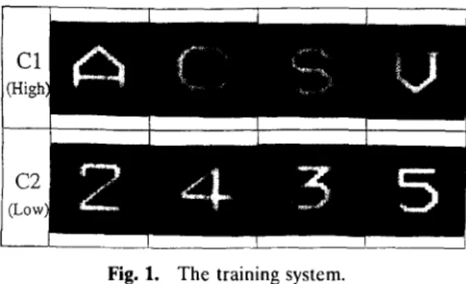
We present the result of computer simulation. The eight patterns
shown in Fig. 1 are used as the training set. The four roman letters {A, C, S, V} are specified as class Cl and the four Arabic numbers {2,3,4,5} are specified as class C2. The sampling grid of each pattern
for the computer simulation is 32 X 32 pixels. The patterns are
presented one by one into the system and the value of the inner product
jw .
XI is compared with 8. If the classification is correct then the next pattern is presented; if it is misclassified then the interconnection weight is updated using eqn (1). Each update is called an iteration. The checkFig. 1. The training system.
of the eight training patterns is called one cycle. The network is said to be converged when all the eight patterns are correctly classified in a single cycle. The simulation results are shown as the curve with open circles in Fig. 2. The figure shows the number of training cycles for the
photorefractive perceptron as functions of the normalized threshold
value 8, where 8 is normalized, without loss of generality, with respect to the inner product of the character IA. A(. It is seen that the network converges within six training cycles when 8 is chosen between O-04 and 0.25. On the other hand, the number of training cycles increases rapidly when 8 is outside this range. Specifically, if 8 is smaller than O-03 or larger than O-27 then the error rate remains 100% for all training cycles
-+- simulation --•-- experiment
24
#
6
Threshold
Fig. 2. The number of training cycles as functions of the normalized threshold values. Open circle curve: computer simulations. Filled circle curve: optical experiments.
172 K. Y. Hsu, S. H. Lin, T C. Hsieh
Fig. 3. Optical system for the implementation of the photorefractive perceptron.
and the system does not converge. This is in agreement with our
prediction in the previous paragraph that the threshold value must be selected in a proper region for the unipolar photodetectors.
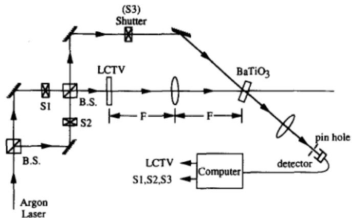
An optical system that was designed to implement the learning
algorithm of eqn (1) is shown in Fig. 3. The detailed principle and
experimental demonstration of this system have been described in Refs
10 and 13. The system utilizes a photorefractive BaTiO, crystal for
recording the holographic interconnection weight vectors. Shutters Sl,
S2 and S3 and two beam-splitters form a double Mach-Zehnder
interferometer for realizing the addition and erasure of the holographic gratings by using the Stoke theorem for wave reflection and transmis-
sion. This interferometer provides a phase control of either 0 (with
shutters Sl, S3 opened and S2 closed) or z (with shutters S2, S3 opened and Sl closed) phase-shift relative to the initial reference interference
fringes. For example, if O-phase was chosen as the reference, then
subtraction of the interconnection strength in the BaTiO, crystal can be achieved by using the n-phase setting in the subsequent exposures, and addition can be achieved by using the original phase setting (O-phase).
By combining these two operations, the learning algorithm of the
photorefractive perceptron has been implemented. In our optical
experiment, the patterns shown in Fig. 1 are used as the training set. In the training phase, each of the training patterns is sent one by one by
the computer to the LCTV as the input to the perceptron. The
magnitude of the inner product of the input pattern and the intercon-
nection weights is detected by the photodetector and then compared
with the desired value which is stored in the personal computer. The
error signal is generated and sent by the computer to turn on the
learning procedure continues until all the patterns are correctly classified. Experimental results are shown as the curve with filled circles in Fig. 2. It is seen that the number of cycles leading to convergence in the optical experiment match well with that of the simulation results, which again confirms our discussion on the restriction of the threshold value.
Next, we discuss the effect of the learning time in each iteration on the convergence of the photorefractive learning network. It is interest- ing to see from eqn (1) that the existing interconnection weight of w(k)
is reduced by a hologram decay factor exp (--t/r) because of the
illumination during each of the weight changes. It is clear that the exposure time t plays an important role in determining the magnitude of the incremental weight change, which is in proportion to [l - exp
(-t/r)], as well as the weight decay factor. The derivation for the
conditional convergence of photorefractive perceptron learning was
given in Refs 11 and 12. Briefly, the perceptron learning will converge provided that the exposure time t is short relative to the time constant z of the crystal. When the exposure time is too long, then the photore- fractive perceptron learning algorithm may not converge to a solution. We have to note that the network discussed in this paper is with a
unipolar photodetector which detects the intensity of the output,
whereas the results derived in Refs 11 and 12 are based on the learning
algorithm that the photodetectors are bipolar and measure the ampli-
tude of the inner products. In the long exposure time region, both
networks have the same characteristics for either unipolar or bipolar
detections, because in this region the holograms of w(k) decay
completely and there is no memory for learning. In the short time
region, however, the convergences of the two networks are different.14
In the bipolar case discussed in Refs 11 and 12, the network can
converge for small intervals of exposure, e.g. t/z = 0.0005 for 8 = 0. On the other hand, for the unipolar case described in eqn (l), the network cannot converge if the exposure time is too short. The curve with open
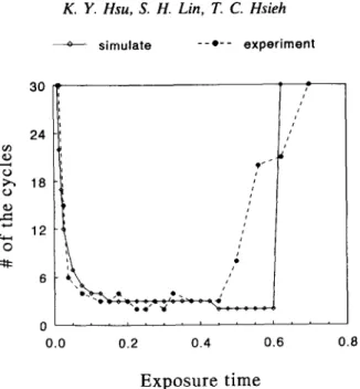
circles in Fig. 4 represents the results of computer simulation. The
training patterns shown in Fig. 1 are used in this simulation. In Fig. 4
the number of training cycles leading to convergence is shown as a
function of the normalized exposure time t/z. It is seen that when t/z is smaller than 0.05 the number of training cycles increases rapidly and
finally the network may not converge. Optical experiments using the
systen of Fig. 3 are performed and the results are shown as the curve
with filled circles in Fig. 4. The experimental results are in good
agreement with the computer simulations.
174 K. Y. Hsu, S. H. Lin, T. C. Hsieh -+- simulate --•-- experiment 24 fi? 0 0.0 0.2 0.4 0.6 0.8 Exposure time
Fig. 4. The number of training cycles as functions of the normalized exposure time. Open circle curve: computer simulations. Filled circle curve: optical experiments.
the convergence behavior of the unipolar photorefractive perceptrons:
the photodetector threshold value 8 and the normalized exposure time
t/z. Only an appropriate selection of these factors can lead to
convergence. One possible way to avoid the influence imposed by the
exposure time is using an algorithm with a learning rule which does not
depend on the updating time t. Furthermore, in order to release the
constraint by the threshold value, bipolar signals should be used for
comparing with the threshold value.14 Conventional perceptron learning
provides these properties. In the next section we describe a hybrid
method for the implementation of the conventional perceptron
algorithm.
3 THE ARCHITECTURE OF THE HYBRID PERCEPTRON
The algorithm of conventional perceptron learning can be written as”
W(P + 1) = W(P) + &MP), (3) where 0 if x(p) is correctly classified 4P) = 1 if x(p) E Cl, but w(p). x(p) < 8 -1 if x(p) E C2, but w(p). x(p) > 8
(4)
R
Fig. 5. The joint transform correlation structure for performing the optical inner product.
Three operations have to be performed for the implementation of this
algorithm: (1) updating rule; (2) memorizing the interconnection
weights w; (3) inner product operation w .x and the thresholding. In
our system the first two operations are achieved using a personal
computer and the third operation is performed by an optical system.
This hybrid system removes the constraints on learning by the hologram
erasure problem and the finite response time of the photorefractive
perceptron. In addition, it combines the advantages of parallelism of
optical computing and the programmability of electronic computers.
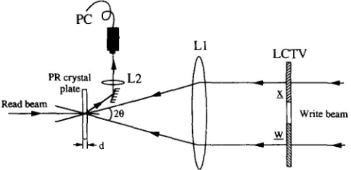
We now describe how to implement the optical inner product using
thin photorefractive crystal plates. The architecture is based on the joint
transform correlator.” Figure 5 shows the schematic diagram. In
operation the two patterns w(p) and x(p) are presented simultaneously onto the LCTV. Each pattern occupies half the screen of the LCTV and they are Fourier transformed by lens Ll. A thin photorefractive plate, which is an iron-doped LiNbO, plate in our case, is put at the Fourier plane of Ll. The interference fringes of the Fourier spectra W(p) and
X(p) induce phase gratings in the photorefractive plate. The gratings
are read out by a read beam incident from the back side of the crystal. In our experiments, the incidence angle 28 = 4O, d = 49 pm. Therefore,
the hologram parameter Q < 1, and the Raman-Nath diffraction
condition for the thin hologram is satisfied. Under this condition, the first order diffraction amplitude of the read beam can be expressed as”
Ed,
“J, -- w n,d( >
c cos 8’
(5)
where 5, is the Bessel function of the first kind, c is the speed of light, w is the light frequency and n, is the photorefractive index change of the LiNbO, plate. Normally, 11, is less than 10m4; thus wnld/c cos 8 << 1 and
176 K. Y. Hsu, S. H. Lin, T. C. Hsieh
the above Bessel function can be approximated by its argument in
parentheses, i.e.
(6)
Furthermore, since YZ] is proportional to the interference fringes,
WX* + W*X, thus, by combining these equations, the first order diffraction is expressed by
Eli, - wx* + w*x. (7)
Finally, EdI is Fourier transformed by lens L2 and the output signal is detected at the center of the Fourier plane. The detected signal can be written as
output signal - ~~{Edl}~x=o,y=o~
-
I~w*wIx=o,y=“l
- lw ’ xl,
(8)
where 9 represents the Fourier transformation. Therefore, the inner
product Iw . xl is obtained.
In this paper we consider the case where x are patterns with positive value elements (O-255 grey levels), whereas w can be bipolar because it is the result of addition and subtraction of the patterns x. Thus, we need
a bipolar spatial light modulator for displaying the bipolar weighted
patterns. In our experiments, the LCTV is operated in amplitude
modulation mode, which has only unipolar grey levels from zero to 255. To resolve this problem, the bipolar w is expressed as the summation of two positive unipolar vectors:
w=w+-w-, (9)
where w+ is the vector whose positive elements are equal to the
corresponding positive elements of w, with the other elements of w+ set to zero, which corresponds to zero and negative elements of w. In a
similar way, w- corresponds to the non-positive part of w. In the
experiment, there are two steps for each inner product operation. In the first step, w+ and x are presented on the LCTV and w+ . x is detected by the optical detector. In the second step, w- and x are displayed and
W- .x is detected.‘Then the two signals are subtracted in the personal computer. Since
W+ .x-w-.x=(w+-w-).x
=w.x, (10)
the inner product w . x is obtained. Thus, w .x is bipolar and the threshold value f3 can also be selected as zero or in bipolar values.
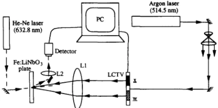
Fig. 6. The set-up for the implementation of hybrid perceptron learning.
4 EXPERIMENTAL RESULTS
The hybrid system shown in Fig. 6 was assembled to implement the
conventional perceptron learning. In the system, a collimated argon
laser beam at 514.5 nm wavelength is used for writing the joint
transform hologram of the input pattern x and the interconnection
weight vector w. The holograms are recorded in the thin photorefrac- tive LiNb03 plate. A He-Ne laser is used for reading the holographic gratings. The readout signal is Fourier transformed by lens L2 to obtain
the inner product. This product is detected by the photodetector and
sent to the personal computer for the learning control. In the
experiment, the initial values of w are set to zero, and the patterns in Fig. 1 were used as the training samples x, of which {A, C, S, V} were specified as class Cl and {2,3,4,5} were specified as class C2. The threshold value was arbitrarily set to zero. Figure 7 shows the training
20 0
6
Cycles
178 K. Y. Hsu, S. H. Lin, T. C. Hsieh
curve. It is seen that the patterns are correctly classified after two cycles of training. After the training is complete, the desired interconnection
weight vectors w+ and w- are obtained and stored in the personal
computer. The weight interconnections w+ and w- are non-volatile and
the system is ready for pattern classification application.
Note that, in principle, we can use the joint transform correlator to
perform the inner product operations in the calculation of w .y for
image classification. However, this calculation needs three steps: w+ . y, w- . y and the subtraction (w’ . y - w- . y). In order to make further use of the parallelism of optical systems for information processing, w+ and
w- are transformed into holographic memories in one crystal volume by
using a multiplexing technique. By doing this, we obtain an optical
processor which performs two-channel inner products, w+ . y and w- . y, in parallel. The subtraction of w+ . y and w- . y is obtained electroni- cally. Thus, the inner product w . y can be achieved in one step. There
are several techniques for recording multiple holograms in a crystal
volume, such as angular, wavelength and phase multiplexing
techniques.‘S22 In our experiment, we chose angular multiplexing.
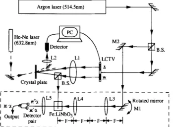
Figure 8 shows the schematic diagram of the complete system; an
optical processor is added into the learning system. In the figure, the
parts outside the dashed block form the learning network, whereas
rotated mirror Ml, lenses L3, L4, L5, photorefractive crystal
Fe:LiNbO, and the detector pair form the optical processor. This
processor is, in fact, the structure of a correlation system. For recording the memories of w+ and w-, first w+ is presented at the position of w
Argon laser (514Snm) I Rotated mirror , MI I I I
on the LCTV. The Fourier transform hologram of w+ is recorded on
the Fe:LiNbO, crystal. A plane wave as the reference beam for this
recording is provided by the argon laser through beam-splitter BS,
mirror M2 and the telescope structure of Ml, L3 and L4. The reference beam intersects with the Fourier spectra W’ at an angle of 90”. Then, similarly, w- is displayed at the same position of w on the LCTV and its
Fourier transform hologram is recorded in the crystal using the
reference beam at a slightly different angle. The multiplexing of the reference beam is provided by rotating Ml of the telescope structure.
After the Fourier transform holograms are recorded, the system is
ready for the pattern classification operation. The patterns to be
classified, for example y, are presented at the position of w on the
LCTV. Then, the inner products
w+
.
y and w- . y are obtainedsimultaneously and are detected by the detector pair. Subtraction of the two detected values provides the final output. Table 1 shows the results of the experiments. The first column shows the input pattern. Corres- ponding to each input there are two optical signals, w+ . y and w- . y, the values of which are shown in the second and third columns. Then, the inner product
w .
x is obtained and is shown in the fourth column. Finally, according to whether the inner is higher or lower than thethreshold value, the fifth column shows the classification of each
pattern. It is seen from the table that the patterns are correctly
classified.
TABLE 1
180 K. Y. Hsu, S. H. Lin, T. C. Hsieh I I Rotatedmirror , Ml I I I I lMector I L__---t?______________-___-A
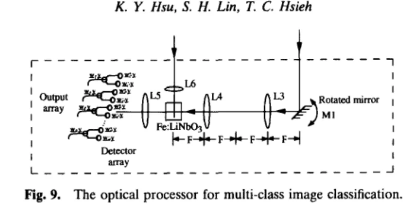
Fig. 9. The optical processor for multi-class image classification.
An additional advantage for using the multiplexing holograms to
perform the inner product operation is that the system can easily be
extended to the multi-category cases.23 In order to perform the
multi-class inner product operation, we need an optical processor to
replace that in the two-category case. To achieve this, the interconnec- tion weight vector for each class is firstly obtained one by one using the hybrid perceptron learning shown in Fig. 6. Each weight vector is stored in the computer. After the training for all the classes is complete, each
weight vector is recorded as a Fourier transform hologram in the
photorefractive crystal using the angular multiplexing technique. The
holograms for the w+ and w- pair of each class are recorded at the
neighboring angles. Thus, there is an M-pair detector array for the
M-class classifier, with the neighboring detectors forming a pair for the detection of w+ . y and w- . y. In this way, the two-category classifica-
tion is extended to the M-class case. The schematic diagram of the
M-class optical processor is shown in Fig. 9.
In our experiment, a system is assembled for the recognition of 10
handwritten Chinese characters. Therefore, there are 10 pairs of
holographic interconnection vectors, 10 for w+ and the other 10 for w-. The 20 weight vectors are recorded in the LiNb03 crystal using the
angular multiplexing technique. When an input image is displayed at
the position of w on the LCTV, the output of the multi-channel inner product is detected by the linear array of photodetectors. The signal is sent to the computer to produce the array of the recognition signal. The experimental results are shown in Table 2. The first column shows the input images. The second column shows the relative value of the inner
product produced by the output array. The third column shows the
recognized output. From the upper two rows of the table, it is seen that both the rotated versions of one character produce a high inner product at the first position of the output array. Both are recognized as class Cl. Also, from the lower two rows of the table, it is seen that both
TABLE 2
Experimental Results of Multi-class Image Classification Input
pattern Inner product w .y Recognized output
Cl
Cl
c4
c4
distorted versions of another character produce high values of inner product at the fourth position of the array. They are recognized as class
C4. The experimental results show that the system can perform
multi-class image classification in parallel, and it has the capability of rotation and distortion invariance.
5 CONCLUSION
We have described the principles of the photorefractive perceptron
learning network. The influences of the finite response time and
hologram erasure problem on the convergence properties of the
photorefractive perceptron are discussed. To overcome these con-
straints for learning, we have presented and demonstrated a novel
system which utilizes thin photorefractive plates for performing optical
inner product and a personal computer for the learning control and
182 K. Y. Hsu, S. H. Lin, T. C. Hsieh
implementation of the conventional perceptron algorithm. Therefore,
the system can work for both the binary images (with levels 0 and 1) and the grey level images. Also, the storage capacity, or the maximum numbers of patterns that can be classified, is equal to two times the
number of the input neurons. After the learning is complete, the
interconnection weights are transformed into holographic memories
using the angular multiplexing technique. The system has been ex-
tended to a multi-channel case to perform parallel processing of
multi-category image classification. Experimental results of using the
optical system for pattern classification are presented. The system
combines the advantages of the learning capability of the perceptron network and the parallel processing of information of optical systems.
ACKNOWLEDGEMENT
This research is supported by the National Science Council, Taiwan,
R.O.C. under contract NSC 83-0416-E-009-012 and NSC 84-2215-E- 009-020.
REFERENCES
1. Rumelhart, D. E. & McClelland, J. M. (Eds), Parallel Distributed
Processing, Vols I and II. MIT Press, Cambridge, MA, 1986.
2. Denker, J. S. (Ed.), Neural Networks for Computing, AIP Conference
Proceedings, Vol. 151. American Institute of Physics, New York, 1986.
3. Hopfield, J. J., Neural networks and physical systems with emergent
collective computational abilities. Proc. Natl. Acad. Sci. U.S.A., 79 (1982),
2554-2558.
4. Hopfield, J. J., Neurons with graded response have collective computa-
tional properties like those of two-state neurons. Proc. Natl. Acad. Sci.
U.S.A., 81 (1984), 3088-3092.
5. Hsu, K. Y., Li, H. Y. & Psaltis, D., Optical implementation of a fully
connected neural network. Proc. IEEE, 78 (1990), 1637-1645.
6. Abu-Mostafa, Y. S. & Psaltis, D., Optical neural computers. Scient. Am.,
256 (1987), 88-94.
7. Psaltis, D., Brady, D. & Wagner, K., Adaptive optical networks using
photorefractive crystals. Appl. Opt., 27 (1988), 1752-1759.
8. Hsu, K., Brady, D. & Psaltis, D., Experimental demonstration of optical
neural computers. Proc. on Neural information Processing Systems, pp.
377-386. American Institute of Physics, New York, 1988.
9. Paek, E. G., Wullert, J. & Patel, J. S., Holographic implementation of a
learning-machine based on a multicategory perceptron algorithm. Opt.
10. Hong, J., Campbell, S. & Yeh, P., Optical pattern classifier with
perceptron learning. Appf. Opt., 29 (1990), 3019-3025.
11. Hsu, K. Y., Lin, S. H. & Yeh, P., Conditional convergence of photorefrac-
tive perceptron learning. Opt. Lett., 18 (1993), 2135-2137.
12. Cheng, C. J., Yeh, P. & Hsu, K. Y., Generalized perceptron learning rule
and its implications for photorefractive neural networks. .I. Opt. Sot. Am.
B., 11 (1994), No. 9.
13. Hsu, K. Y., Lin, S. H., Cheng, C. J., Hsieh, T. C. & Yeh, P., An optical
neural network for pattern recognition. ht. J. Opt. Comput., 2 (1991),
409-423.
14. Cheng, C. J., Hsu, K., Lin, S. H., Hsieh, T. C. & Yeh, P., An optical
learning network with amplitude detection. Proc. SPIE, 1806 (1992),
488-499.
15. Rosenblatt, F., Principles of Neurodynamics: Perceptron and the Theory of
Brain Mechanisms, p. 97. Spartan Books, Washington, DC, 1962.
16. Yu, F. T. S. & Lu, X. J., A real-time programmable joint transform
correlator. Opt. Commun., 52 (1984) 10-16.
17. Yariv, A. & Yeh, P., Optical Waves in Crystals, p. 358. Wiley Interscience,
New York, 1983.
18. Chen, F. S., laMacchia, J. T. & Fraser, D. B., Holographic storage in
lithium niobate. Appl. Phys. Lett., 13, No. 7 (1968), 223-225.
19. Mok, F. H., Tackitt, M. C. & Stoll, H. M., Storage of 500 high resolution
holograms in a LiNb03 crystal. Opt. Lett., 16 (1991), 605-607.
20. Mok, F. H., Angle-multiplexed storage of 5000 holograms in lithium
niobate. Opt. Lett., 18 (1993), 915-917.
21. Rakuljic, G. A., Leyva, V. & Yariv, A., Optical data storage by using
orthogonal wavelength-multiplexed volume holograms. Opt. Lett., 17
(1992), 1471-1473.
22. Denz, C., Pauliat, G., Roosen, G. & Tschudi, T., Potentialities and
limitations of hologram multiplexing by using the phase-encoding tech-
nique. Appl. Opt., 31 (1992), 5700-5705.
23. Hsu, K. Y., Lin, S. H. & Hsieh, T. C., Real-time image processing using
photorefractive crystals, Paper 27C1, Znt. Conf on Optical Memory &