REFERENCES
1. J. Guo, L. Tsang, W. Asher, K.-H. Ding, and C.-T. Chen, Application of dense media radiative transfer theory for passive microwave remote sensing of foam covered ocean, IEEE Trans Geosci Remote Sensing 39 (2001), 1019 –1027.
2. D. Chen, L. Tsang, L. Zhou, S.C. Reising, W. Asher, L.A. Rose, K.H. Ding, and C.-T. Chen, Microwave emission and scattering of foam based on Monte Carlo simulations of dense media, IEEE Trans Geosci Remote Sensing 41 (2003), 782–790.
3. L. Tsang and J.A. Kong, Scattering of electromagnetic waves, Adv Topics 3, John Wiley, New York (2001), p. 300.
4. L. Tsang, J.A. Kong, K.H. Ding, and C.O. Ao, Scattering of electro-magnetic waves, Numer Simulations 2 (2001), 179 –190.
5. V. Jandhyala, B. Shanker, E. Michielssen, and W.C. Chew, A fast algorithm for the analysis of scattering by dielectric rough surfaces, J Opt Soc Am A 15 (1998), 1877–1885.
6. S. Kapur and D.E. Long, IES3: A fast integral equation solver for efficient 3-dimensional extraction, Proc 37thInt Conf Computer Aided Design, 1997, pp. 448 – 455.
7. L. Tsang and Q. Li, Wave scattering with UV multilevel partitioning method for volume scattering by discrete scatterers, Microwave Opt Technol Lett 41 (2004), 354 –361.
8. L. Tsang, D. Chen, P. Xu, Q. Li, and V. Jandhyala, Wave scattering with the UV multilevel partitioning method: 1. Two-dimensional prob-lem of perfect electric conductor surface scattering, Radio Sci 39 (2004).
9. L. Tsang, Q. Li, P. Xu, D. Chen, and V. Jandhyala, Wave scattering with UV multi-level partitioning method 2: three-dimensional problem of nonpenetrable surface scattering, Radio Sci 39 (2004).
10. R.J. Burkholder and J.F. Lee, Fast duMGS block-factorization al-gorithm for dense MoM matrices, IEEE Trans Antennas Propagat 52 (2004), 1693–1699.
11. D. Weaire and S. Hutzler, The physics of foams, Clarendon Press, Oxford, 1999, pp. 152–158.
12. L. Tsang, J.A. Kong, and K.H. Ding, Scattering of electromanectic waves. Theories and Applic 1, John Wiley, New York (2000), 260 – 268.
13. M.G. Duffy, Quadrature over a pyramid or cube of integrands with a singularity at a vertex, SIAM J Numer Anal 19 (1982), 1260 –1262. 14. L.A. Klein and C.T. Swift, An improved model for the dielectric
constant of sea water at microwave frequencies, IEEE Trans Antennas Propagat AP-25 (1977), 104 –111.
© 2005 Wiley Periodicals, Inc.
EVIDENCE OF BIREFRINGENCE AND
ANOMALOUS
ELECTROMAGNETIC-PULSE PROPAGATION IN AN ORGANIC
LIGHT-EMITTING DIODE
Sheng-Chieh Tai,1Jyh-Long Chern,1Yueh-Chuan Huang,2
Mei-Rurng Tseng,2and Hsien-Kuang Lin2
1Department of Photonics
Institute of Electro-Optical Engineering, Display Institute Microelectronics and Information System Research Center National Chiao Tung University
Hsinchu 300, Taiwan
2Material Research Laboratory
Industrial Technology Research Laboratory Hsinchu, Taiwan
Received 3 December 2004
ABSTRACT: High-speed electromagnetic characteristics of an organic
light-emitting diode (OLED) are explored in this paper. When a high-frequency (⬃14 GHz) microwave pulse is injected into an OLED, the pulse is split into two peaks: one peak is delayed by 1.725 ns and an-other one is advanced by 0.183 ns, which also suggests the existence of an extremely low-speed group velocity. The effective thickness of the OLED sample is⬃355.8 nm and, as a result, the effective index of re-fraction is⬃107when the splitting phenomenon occurs. © 2005 Wiley
Periodicals, Inc. Microwave Opt Technol Lett 45: 450 – 452, 2005; Published online in Wiley InterScience (www.interscience.wiley.com). DOI 10.1002/mop.20850
Key words: organic light-emitting diode; superluminal effect;
electro-magnetic-pulse propagation
1. INTRODUCTION
Electromagnetic-pulse propagation has been a longstanding issue, ever since the founding of electromagnetic theory by Maxwell [1], and efforts to revisit this classical topic are readily found in the literature. It also has provided a variety of novel applications such as fiber communication and soliton communication [2]. On the other hand, there is an intriguing topic concerning the fundamental aspect of electromagnetic theory, that is, the propagation limit set by the velocity of light. It is known that the velocity of an electromagnetic pulse passing through a normal dispersive me-dium is well characterized by group velocity. According to clas-sical theory [1], the group velocity of a pulse in linear dispersion and a nonabsorbing medium is described as
vg⫽ d dk ⫽
c
n共兲 ⫹ 共dn/d兲, (1)
where and k are the angular frequency and wave vector of the electromagnetic wave, respectively, and c is the velocity of light in a vacuum. Typically, vg is less than c. But, for an anomalous
dispersion, dn/d ⬍ 0, which leads to vgbeing larger than c. This
violates the theory of relativity, which states that no velocity can be larger than c. Actually, in this case the group velocity lost its meaning as a signal velocity [3]. Indeed, contrary to common group velocity, Brillouin introduced the energy velocity vE, which
is more meaningful [3]. The true energy velocity can be defined as the rate of energy flow divided by the stored energy density of the electromagnetic wave, as correctly derived by Loudon [4], even though an anomalous dispersion leads the pulse to seemingly advance. This phenomenon of pulse advance is referred to as the “superluminal effect.” Given the current interest, one can find the superluminal effect in the literature, with regard to passive absorp-Figure 7 Brightness temperature as a function of frequency at 55°
observation angle (the temperature of seawater is 10°C; the side length of Kelvin’s cell is 0.672 mm; fwis 1.0%)
tion, passive reflective, or in active transparent media. In the case of passive absorption, Chu and Wong showed the superluminal effect in the GaP:N medium in the range of visible light [5]. The group velocity reported in their work ranged from c/ 2.87 to c/30 at different laser frequencies. In this paper, we will provide another novel example of superluminality, namely, an organic light-emit-ting diode (OLED) sample [6] interaclight-emit-ting with high-frequency microwaves.
2. SAMPLE DESCRIPTION
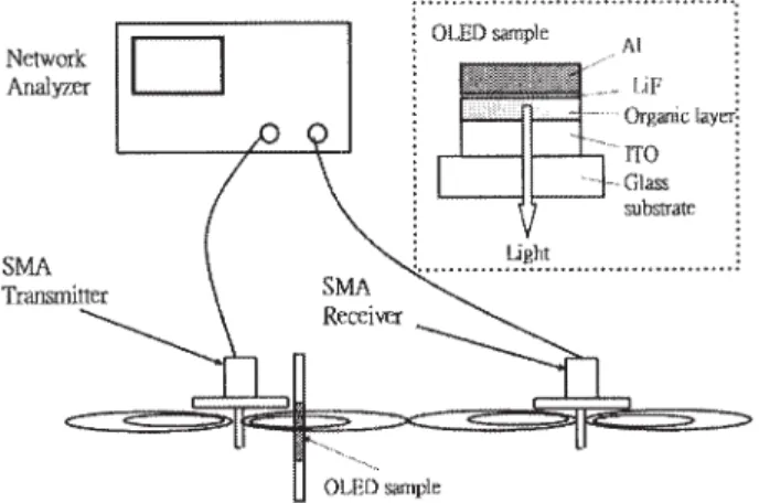
An organic light-emitting diode is a very interesting optoelectronic material, and has potential commercial applications in flat displays and flexible displays [7]. In our case, four different layers of materials basically make up the OLED sample. Referring to the inset of Figure 1, the organic layer is sandwiched by the Al/LiF bilayer cathode and the ITO anode. The thickness of Al and LiF are 120 and 0.3 nm, respectively, and for the case of the ITO anode, the thickness is 150 nm. From top to bottom, the organic layer consists of the following elements: (i) Alq3, that is, Tris(8-hydroxyquinolinato)aluminum(III), as the electron-transporting layer; (ii) BCP, that is, 2,9-Dimethyl-4,7-diphenyl-1,10-phenanth-roline, as the hole-blocking layer; (iii) DPVBi with yellow emitter dopant; (iv) DPVBi with blue emitter dopant; (v) NPB, that is, N,N⬘-Di(naphthalen-2-yl)-N,N⬘-diphenyl-benzine, as the hole-transporting layer. The total thickness of the organic layer is 85.5 nm. In order to protect the OLED, the topside was capped by glass, with the total thickness of glass being 1.5 mm. When the OLED sample was biased with a dc voltage (typically, about 6 V), white light was emitted. The lighting area of the OLED is 0.5⫻ 0.6 cm in the experiments. It was found that, whether the OLED is lighted or not, the absorption line does not change significantly. Here, we report the results of an OLED with power OFF and power ON. Furthermore, we explore the high-frequency characteristics of OLED, which are seldom addressed in the literature.
3. EXPERIMENTAL SETUP AND RESULTS
The experimental setup is shown in Figure 1. Basically, in this experiment we used a network analyzer (HP 8720D) to evaluate the microwave-transmission characteristics of the OLED. Typi-cally, this microwave network analyzer can deliver 5-dBm power, from 50 MHz to 20.05 GHz. Because the sample is small, instead of a typical horn antenna, two SMA connectors were used as the emitter and receiver, respectively. In this case, we used a common two-hole flange plug receptacle (Solder Pot Contract) for the SMA connector. Referring to Figure 1, the filed emitting pattern of the
SMA connector is narrow and is suitable to be used as either the emitter or the receiver. The SMA connectors were directed to the sample such that the emission and detection were along the same axis. Experimentally, we found that the working range is from 10 to 20 GHz. Outside the working range, the sensitivity is small. Therefore, we focused our experiment on the frequency range from 7 to 20 GHz. After connecting the SMA antennas, the receiver received⫺40-dBm power from 7 to 20.05 GHz and below ⫺55 dBm from 50 MHz to 7 GHz.
In the experiment, the OLED sample was placed about 2.7 cm away from the SMA transmitter, and the lighting area was posi-tioned immediately behind the transmitter. The receiver was placed 7-cm away from the transmitter. The entire sample was held by a translation stage, and its position could be set automatically. In our experiment, we used two methods to explore the microwave characteristics of the OLED sample. The first one was to sweep the transmission characteristics of the OLED with a wide range of microwaves. With this method, the energy of a single frequency is generated and, after passing through the OLED sample, it is detected by the receiver. It was characterized by the S21parameter, which is the ratio of the incident wave of the voltage at port 1 to the emerging wave of the voltage at port 2 [8]. Port 1 is the transmitter SMA, and port 2 is the receiver SMA. The second method consists of employing the default function of the network analyzer to explore the transmission characteristics of pulse prop-agation via time-domain transferring.
For comparison, we considered FR4 material with a thickness of 0.1 cm. The dotted line in Figure 2 shows that the measurement of the normalized S21 parameters for the FR4 materials ranged from 10 to 20.05 GHz. The near-flat spectrum suggests that the FR4 material is of normal (transparent) medium from 11 to 12 GHz and the transferred pulse was delayed by 0.03 ns, as shown by the dashed line in Figure 3. For the OLED sample, we swept the normalized S21 data from 10 to 20.05 GHz, and found that the appearance of absorption is evident, especially from 13.5 to 14.5 GHz, as shown by the solid line in Figure 2. It is interesting to note that this shows that now the anomalous dispersion of microwave Figure 1 Experimental setup and the field pattern of the SMA antennas
(the inset is the configuration of the OLED sample)
Figure 2 Transmission spectrum in terms of the normalized S21 param-eter. The solid and dotted lines express the S21data of the OLED and FR4 materials, respectively. The value shown is averaged over five measure-ments. The range of fluctuation is denoted by the standard deviation of the measured data. For FR4 material, in which the maximum of standard deviation for the whole range is 0.11 dB, and the average of standard deviations is 0.04 dB; for the OLED sample; the maximum standard deviation is 0.96 dB and the average of standard deviations is 0.28 dB
electromagnetic wave does occur in the OLED sample. Hence, the superluminal effect may occur in the OLED sample as well. Next we examine the result of the time-domain transformation, using a pulse that includes the microwave range from 13.5 to 14.5 GHz through free space as a reference. The pulse through the power-off OLED sample was separated into two parts, as shown by the short dashed line in Figure 3. One of the pulse peaks was delayed by a time scale of 1.725 ns. On the other hand, another pulse peak was advanced by 0.183 ns with respect to the main peak of the pulse measured in free space, as shown by a downward arrow (2). Compared to the case of power-ON (6-V) OLED, this phenome-non is almost the same as the case of power-OFF OLED; the insert in Figure 3 shows the difference between these two cases. The thickness of the OLED sample (including the organic, cathode, and anode layers, but excluding the glass substrate and cap) was 355.8 nm. On the other hand, because the glass contributed a small delay (Ⰶ 0.1 ns), and according to Eq. (2), the relation between the delay time and the optical path is given by
⌬t ⫽共n ⫺ 1兲 Lc . (2)
where the “effective” indices of refraction of the OLED sample for the two peaks were 1.45⫻ 108and ⫺1.54 ⫻ 107, respectively.
The results of the measurement, phase advance, and peak splitting are amazing, and they provide a unique example of superluminal-ity. However, the results of their deduction are even more aston-ishing. These results indicate: (i) a possible existence of negative-index materials; (ii) that the negative-index is effectively extremely large. The existence of ultra-high indices of refraction may sound in-credible; nevertheless, the ultra-high index has been employed previously in diffractive optics (that is, the Sweatt model) for modeling the diffractive optical surface [9]. This suggests that the OLED sample is effectively an “unusual” birefringence medium in the corresponding microwave range. The index is extremely large and the propagation has been greatly slowed down. By calculating the group velocity, we can deduce the values of the group velocity to be 2.06 and⫺19.5 m/s, respectively, which indicates that the
group velocity has been slowed down, even to an order of seven, in comparison with the speed of light.
4. CONCLUSION
In conclusion, a novel high-speed-frequency electromagnetic char-acteristic of a power-OFF blue-light thin-film OLED sample has been reported. A superluminal phenomenon has been experimen-tally identified. The mechanism of this superluminal effect may be attributed to the fact that the OLED sample absorbs the energy and does not transfer it nonradiatively. Under this circumstance, the incident pulse can modulate the stored energy and induce the superluminality. However, a theoretical exploration remains to be done. The reported superluminal phenomenon occurs when the OLED sample is operated over an absorption band where anom-alous dispersion occurs. It should be noted that different samples of OLEDs were also tested, and that the superluminal effects persist, provided that the OLED is operated over the absorption band and that anomalous dispersion occurs.
ACKNOWLEDGMENTS
The NCTU group thanks Y. C. Huang for his assistance with the experimental setup. This work is supported in part by the National Science Council of Taiwan, ROC, under contract no. NSC92-2112-M009-040.
REFERENCES
1. J.D. Jackson, Classical electrodynamics, 3rd ed., Wiley, New York, 1999.
2. G.P. Agrwall, Nonlinear fiber optics, 3rd ed., Academic Press, New York, 2001.
3. L. Brillouin, Wave propagation and group velocity, Academic Press, New York, 1960.
4. R. Loudon, The propagation of electromagnetic energy through an absorbing dielectric, J Phys A3 (1970), 233–245.
5. S. Chu and S. Wong, Linear pulse propagation in an absorbing medium, Phys Rev Lett 48 (1982), 738 –741.
6. A. Dodabalapur, Organic light emitting diodes, Solid State Commu 102 (1997), 259 –267.
7. A. Mikami, T. Koshiyama, and T. Tsubokawa, High-efficiency color and white-light polymer devices with high-index-of-refraction flexible plastic substrate, Soc Infor Display 2004 Symp Dig Technical papers (SID2004), Vol. 35, pp. 146 –149.
8. D.M. Pozar, Microwave engineering, 2nded., Wiley, New York, 1998, p. 196.
9. W.C. Sweatt, Mathematical equivalence between a holographic optical element and an ultra-high index lens, J Optics Soc Am 69 (1979), 486 – 487.
© 2005 Wiley Periodicals, Inc.
SOLID-ANGLE FACTOR IN THE
MAGNETIC-FIELD INTEGRAL EQUATION
O¨ zgu¨r Ergu¨l and Levent Gu¨relDepartment of Electrical and Electronics Engineering Bilkent University
TR-06800, Bilkent Ankara, Turkey
Received 18 November 2004
ABSTRACT: The magnetic-field integral equation (MFIE) contains a
geometry-dependent solid-angle factor due to the limit value of the mag-netic field at the source region. Determination of the solid-angle factor
Figure 3 Pulse waveforms in the time domain. The solid line is the reference (incident) pulse, and the short dashed and dotted lines denotes the pulse train through power-OFF and power-ON OLEDs measured by the receiver, respectively. The dashed line denotes the result of the pulse passing through FR4 sample. The insert shows the difference between the power-ON and power-OFF cases (6V-0V)