具多齊質性處理器核心之多媒體串流處理架構
98
0
0
全文
(2) 具多齊質性處理器核心之 多媒體串流處理架構. Media Streaming Architecture with Homogeneous Processor Cores. 研 究 生:劉嘉儀 指導教授:闕河鳴. Student:Chia-Yi Liou 博士. Advisor:Dr. Herming Chiueh. 國立交通大學 電信工程學系碩士班 碩士論文. A Thesis Submitted to Department of Communication Engineering College of Electrical and Computer Engineering National Chiao Tung University in Partial Fulfillment of the Requirements for the Degree of Master of Science in Communication Engineering July 2007 Hsinchu, Taiwan. 中華民國九十六年七月.
(3) 具多齊質性處理器核心之 多媒體串流處理架構 研究生:劉嘉儀. 指導教授:闕河鳴 博士. 國立交通大學 電信工程學系碩士班. 摘要. 隨著科技的發展與進步,在現今的生活中應用於多媒體運算之可攜式嵌入式 系統的重要性與日俱增。然而由於傳統運算模型中之記憶體存取模型與處理核心 和記憶體間的效能間隙落差,導致多媒體運算無法有效率的對應並且實現在傳統 的處理器架構模型上。另外在硬體實現的系統架構上亦是產生效能無法提升的重 要因素之ㄧ。因此所提出的多媒體處理架構採用史丹佛大學提出之串流處理模型 配合上多種硬體實現的系統架構來克服傳統處理器架構所造成效率低落。並且提 供一具高平行度和有效率運算速率的多媒體運算平台。. 在本論文中,設計並下線製作一個與 AMBA 介面相容之多媒體處理單元作 為構成具多齊質性處理核心之多媒體串流處理架構的核心運算單元。除此之外亦 設計實做浮點運算處理器,利用此浮點運算處理器提供此一與 AMBA 介面相容 之多媒體處理單元有效率的浮點運算處理能力,使其可以更廣泛的應用於各種多 媒體處理運算中。透過不同運算單元與架構間的效能評估與比較,證實了僅需要 I.
(4) 些許的硬體成本即可提供更有效率且更廣泛的多媒體運算處理能力。另外此效能 評估與比較亦證實了具多齊質性處理核心之多媒體串流處理架構在擁有不同數 目之處理核心時,在合理的硬體成本之下其效能可以有效的提升。. II.
(5) Media Streaming Architecture with Homogeneous Processor Cores Student: Chia-Yi Liou. Advisor: Dr. Herming Chiueh. Department of Communication Engineering National Chiao Tung University Hsinchu, Taiwan. Abstract As the evolution of information technology, embedded systems with media applications for portable devices are more and more important in modern life. However, the conventional processor architecture does not handle the processing requirement of media applications very well since the characteristics of media applications and other inheritance disability from conventional microprocessor architecture’s memory accessing model and processor-memory performance gap. Recent research shows that the stream processing model and stream processor architecture are suitable for media applications. However, software implementations for a streaming processor are not a trivial job since it evolves a lot of hand and manual optimization in memory exchange and tread deployment to different processor element or functional unit. In this thesis, a processing element for reconfigurable homogenous ALU cluster and its Advanced Microcontroller Bus Architecture (AMBA) platform interface has been designed and implemented. The proposed design integrated platform based design methodology and stream processing model to overcome the challenge of media applications. The proposed homogenous ALU cluster is utilized as a reconfigurable hardware accelerator for specific and different functions in media applications. The chosen AMBA interface provides an integration platform for embedded operating system and programming development environment. The combination of these methodologies provides a turnkey solution for media applications development in modern portable devices. III.
(6) The ALU cluster IP with AMBA interface is taped out using TSMC 0.15um technology and operates at 100MHz. The chip area is 3.9*3.9 mm2 and gate count is 0.2 million. A 4-layer FRP printed circuit board is designed and fabricated as the daughter card for system integration. The daughter card carries the designed chip is integrated to ARM versatile platform board as the system integration and application development environment. In addition, a floating point operation unit for ALU cluster IP is proposed and implemented and it will be integrated with ALU cluster IP as the future revision of the hardware accelerator. The hard macro of the floating point unit operates at 75MHz, its area and gate count is 0.415mm2 and 0.02 million respectively. The performance evaluation and comparison in floating point operation benchmark between different proposed architectures are presented. Media applications can be developed for proposed reconfigurable homogenous processing elements in the future using the chips and systems build in this thesis.. IV.
(7) Acknowledgement 本篇碩士論文得以順利完成,首先要感謝我的指導教授 闕河鳴 博士。老師擁有淵博的學識,總能讓學生在研究遇到瓶頸的時候給予 寶貴的指導及建議,使我能夠突破與進步。更由於老師在平日培養學 生獨立思考與分析、解決問題的能力,使我對於研究的領域建立正確 的態度及觀念。. 再者要感謝晶片系統設計實驗室的學長姐、同學以及學弟妹們, 在我的研究上及生活上给與諸多的指教及幫助。因為你們的支持,才 讓我得以擁有一段快樂充實的碩士班研究生活,謝謝大家。. 最後,我要感謝父母的栽培與養育之恩、所有關心我的家人與朋 友、以及我生長的這塊土地、社會與國家。. 誠心感謝並祝福所有提攜幫助我和支持鼓勵我的大家,謝謝各位 並祝福各位。. 劉嘉儀. V.
(8) CONTENTS 中文摘要……………………………………………………………………. Ⅰ. English Abstract..…………………………………………………………... Ⅲ. Acknowledgment………………………………………………………….... Ⅴ. Content…………………………………………………………………….... Ⅵ. List of Tables……………………………………………………………….. Ⅷ List of Figures……………………………………………………………… Ⅸ. Chapter 1 Introduction……………………………………………………. 1 1.1 Motivation……………………………………………………………... 1 1.2 Organization…………………………………………………………… 3 Chapter 2 Background and Challenges…………………………………... 4. 2.1 Issues of Programming Model………………………………………… 2.2 Issues of System Architecture………………………………………….. 4 6. Chapter 3 Development Roadmap and Proposed Design……………….. 10 3.1 Developmental Roadmap……………………………………………….. 3.1.1 Motivation………………………………………………………….. 3.1.2 Roadmap………………………………………………………….... 3.1.2.1 Stream Programming Model…………………………………... 3.1.2.2 Developmental Roadmap……………………………………… 3.2 An ALU cluster……………………………………………………….. 3.2.1 Micro-Architecture of an ALU cluster............................................... 3.3 An ALU cluster Intellectual Property………………………………… 3.3.1 Overview of AMBA………………………………………………... VI. 11 11 11 11 14 17 17 18 18.
(9) 3.3.1.1 Introduction of AMBA AHB…………………………………... 3.3.1.2 Bus Interconnection…………………………………………… 3.3.1.3 Signals for the protocol of AMBA AHB slave………………… 3.3.1.4 Basic Transfer…………………………………………………. 3.3.1.5 Transfer Type………………………………………………….. 3.3.1.6 Address Decoding……………………………………………... 3.3.1.7 Burst Operation………………………………………………... 3.3.2 Micro-Architecture of an ALU cluster Intellectual Property………. 3.4 Floating Point Units for the ALU cluster IP………………………….. 3.4.1 Design Consideration……………………………………………….. 20 21 22 24 25 26 27 28 32 33. Chapter 4 Implementation Results and Performance Evaluation…….... 37. 4.1 Implementation and Testing Results of An ALU cluster………………... 38. 4.2 Verification and Implementation Results of An ALU cluster Intellectual Property…………………………………………………………………. 4.2.1 An ALU cluster IP with Magnetic RAM…………………………... 4.2.1.1 Introduction of Magnetic RAM……………………………….. 4.2.1.2 Modified ALU cluster IP for Magnetic RAM…………………. 4.2.2 Implementation Results…………………………………………….. 4.2.3 Circuit Verification…………………………………………………. 4.2.4 Chip Testing………………………………………………………... 4.3 Circuit Implementation and Results of Floating Point Units for the ALU cluster IP………………………………………………………….. 4.4 Performance Evaluation and Comparison……………………………… 4.4.1 Selected Benchmark……………………………………………….. 4.4.2 Evaluation and Comparison Results................................................... 43 43 44 44 45 50 55 57 62 63 64. Chapter 5 Conclusion and Future Work…………………………………. 80 5.1 Conclusion…………………………………………………………….. 5.2 Future Work……………………………………………………………. 80 81. Bibliography………………………………………………………………... 82. VII.
(10) LIST of TABLES Table 2.1. System Architecture vs. media application…………………… 9. Table 3.1 Table 3.2 Table 3.3 Table 3.4 Table 3.5. Comparison between programming models………………….. Burst Signal Encoding………………………………………... Active Byte Lanes for a 32 bits big endian data bus…………. Active Byte Lanes for a 32 bits little endian data bus………... Format of single and double precision IEEE 754 floating. 14 27 28 28. Table 3.6. point number………………………………………………….. Effective Range of the IEEE 754 floating point number…….... 34 34. Table 4.1 Table 4.2 Table 4.3 Table 4.4 Table 4.5 Table 4.6. Implementation Results Summary of ALU cluster…………… Testing results summaries of ALU cluster……………………. Summary of Implementation Characteristics…………………. The Definitions of I/O the ports………………………………. Summary of the Implementation Results…………................... Performance Evaluation Results for Original Integer. 38 43 46 49 59. Table 4.7. Architecture…………………………………………………… 66 Performance Evaluation Results for Floating Point Unit and. Table 4.8. Original Integer Architecture Mixed………………………….. 67 Performance Evaluation Results in Execution Time…………. 71. VIII.
(11) LIST OF FIGURES Fig 2.1 Fig 2.2 Fig 2.3 Fig 2.4 Fig 2.5. Conventional Programming Model......................................... Processor-Memory Performance Gap………………………. Application Specified Integrated Circuit Design…………… An Example of Platform-Based Architecture……………….. A Diagram of Reconfigurable Architecture………………….. 5 5 6 7 8. Fig 3.1 Fig 3.2 Fig 3.3 Fig 3.4 Fig 3.5. Stream Programming model………………………………… Example of 1024-points radix-2 Fast Fourier Transform…… Example of Stereo Depth Extraction………………………... Development roadmap………………………………………. Micro-Architecture of ALU cluster…………………………. Diagram of AMBA-based system…………………………... Diagram of AMBA AHB interconnection…………………... Diagram of AHB slave interface……………………………. An example of simple transfer……………………………… The example of the transfer extended………………………. Slave Selected Signal……………………………………….. The Proposed ALU Cluster IP Architecture………………… The state diagram of the finite state machine……………….. An ALU cluster IP with Floating Point Unit Supported. 12 13 13 15 17. Architecture………………………………………………….. 36. Physical Layout of an ALU cluster…………………………. Floorplan and Pad Assignment of an ALU cluster………….. Microphotograph of taped out ALU cluster………………… An ALU cluster with CQFP128 package…………………… An ALU cluster with PCB board…………………………… Modified ALU cluster IP architecture for MRAM…………. Physical Layout of an ALU Cluster IP……………………… Pads Assignment of an ALU Cluster IP…………………….. Die Microphotograph of Taped Out Chip…………………… Photograph of Prototype with Package……………………... The input function and coefficients of the FIR filter system... Output results of the FIR filter system……………………… Post-Layout Simulation Results of an ALU cluster IP (Ⅰ)…. 39 40 41 41 42 45 46 47 48 48 51 52 53. Fig 3.6 Fig 3.7 Fig 3.8 Fig 3.9 Fig 3.10 Fig 3.11 Fig 3.12 Fig 3.13 Fig 3.14. Fig 4.1 Fig 4.2 Fig 4.3 Fig 4.4 Fig 4.5 Fig 4.6 Fig 4.7 Fig 4.8 Fig 4.9 Fig 4.10 Fig 4.11 Fig 4.12 Fig 4.13(a). IX. 20 22 23 24 25 26 29 31.
(12) Fig 4.13(b) Fig 4.13(c) Fig 4.13(d) Fig 4.13(e) Fig 4.14 Fig 4.15 Fig 4.16 Fig 4.17 Fig 4.18 Fig 4.19 Fig 4.20. Post-Layout Simulation Results of an ALU cluster IP (Ⅱ)… Post-Layout Simulation Results of an ALU cluster IP (Ⅲ)… Post-Layout Simulation Results of an ALU cluster IP (Ⅳ)… Post-Layout Simulation Results of an ALU cluster IP (Ⅴ)… The Printed Circuit Board (PCB) for the manufactured chip.. Testing Equipments – Logic Analyzer System……………… Connection between the Chip and Testing Equipments…….. Physical Layout of the Type 1 FPU macro………………….. Physical Layout of the Type 2 FPU macro………………….. Physical Layout of the Type 3 FPU macro………………….. Full View of Post-Layout Simulation Results for Type 1. 53 54 54 55 55 56 56 58 58 59. Fig 4.21. FPU………………………………………………………….. 60 Interception of Post-Layout Simulation Results for Type 1. Fig 4.22. FPU………………………………………………………….. 60 Full View of Post-Layout Simulation Results for Type 2. Fig 4.23. FPU………………………………………………………….. 61 Interception of Post-Layout Simulation Results for Type 2. Fig 4.24. FPU………………………………………………………….. 61 Full View of Post-Layout Simulation Results for Type 3. Fig 4.25. FPU………………………………………………………….. 62 Interception of Post-Layout Simulation Results for Type 3. Fig 4.26 Fig 4.27. FPU………………………………………………………….. 62 Flowchart of the length 32 Split-Radix FFT algorithm……... 64 Performance Evaluation of one cluster included in these. Fig 4.28. architectures…………………………………………………. 68 Performance Evaluation of two clusters included in these. Fig 4.29. architectures…………………………………………………. 69 Performance Evaluation of four clusters included in these. Fig 4.30. architectures…………………………………………………. 69 Performance Evaluation of eight clusters included in these. Fig 4.31. architectures…………………………………………………. 70 Performance Evaluation of one cluster included in execution. Fig 4.32. time………………………………………………………….. 72 Performance Evaluation of two clusters included in. Fig 4.33. execution time………………………………………………. 73 Performance Evaluation of four clusters included in execution time……………………………………………….. X. 74.
(13) Fig 4.34 Fig 4.35 Fig 4.36 Fig 4.37 Fig 4.38. Fig 5.1. Performance Evaluation of eight clusters included in execution time………………………………………………. Comparison of Performance Normalized in execution cycles Comparison of Performance Normalized in execution time... Performance Comparison for Different Number of Clusters. 75 76 76. used in cycles........................................................................... 78 Performance Comparison for Different Number of Clusters used in execution time……………………………………….. 78. RealView Versatile Platform Baseboard for ARM926EJ-S…. 81. XI.
(14) Chapter 1 Introduction. CHAPTER. 1. Introduction 1.1 Motivation Portable systems are more and more important. They become essentials of our life. Furthermore, media applications are becoming a dominant portion of processing for portable entertainment system in modern life. Multimedia processing applications are characterized by large available parallelism, little data reuse and high computation to memory access ratio. Large available parallelism due to each data stream is independent to others, so each stream is possible to be operated concurrently. The reason for the characteristic of little data reuse is that typical data reference in media applications require a single read and write per global data element. High computation to memory access ratio is needed because of large amount of data operations [1 - 4]. Thus these characteristics poorly match conventional general purpose processor architecture. The conventional programming model and processor architecture dealt with media applications traditionally are not efficient because of the characteristics of media applications, its memory accessing model and processor-memory performance gap [5]. In addition to programming models, system architectures used to implement the whole media processing system are also key factors to affect the efficiency of processing. System architectures such as application specific integrated circuits (ASIC), platform-based architecture and reconfigurable architecture are used to implement the hardware for media applications. However, these architectures for media processing have their own drawbacks separately. They suffer from lacking of flexibility, programmability, and inefficient communication bandwidth. The issues of programming model and system architecture mentioned above limit the processing requirement needed for modern media application in mobile system. -1-.
(15) Chapter 1 Introduction. However, streaming programming model has been suggested as an efficient programming model for both media applications and base-band architecture for software defined radios [6] [7]. In order to build next generation media processing system, advantages from different system architectures are integrated. The pros of reconfigurable architecture and platform-based architecture will overcome the drawbacks of using above-mentioned architecture separately. This thesis presented a processing element for reconfigurable homogenous ALU cluster and its Advanced Microcontroller Bus Architecture (AMBA) platform interface has been designed and implemented. The proposed design provides enough processing requirement for media applications and utilized as a reconfigurable hardware accelerator for specific and different functions in media applications. AMBA AHB interface in this design provides an integration platform for embedded operating system and programming development environment. The combination of these design methodologies will be a suitable solution in development applications for portable devices. All design and verification of the proposed architecture are finished with cell-based design flow. The chip is taped out using TSMC 0.15um CMOS technology and operates at 100MHz. The die size and gate count are 15.2 mm2 and 0.2 million respectively. Utilize COB (PGA256) as package material. The pad number of proposed chip is 130. The designed chip with daughter card will be integrated with ARM926EJ-S versatile baseboard to form a media streaming system and as the development environment for applications. Furthermore, a floating point operation unit is critical in the majority of media application and makes the applications efficient. A floating point operation unit for ALU cluster IP is proposed and implemented in this thesis as a modified version of the hardware accelerator. The hard macro of three different type floating point unit operates at 75MHz, 25MHz and 25MHz, its area and gate count is 0.415 mm2, 0.529mm2 , 0.396mm2 and 0.02million, 0.03 million, 0.02 million respectively. Then the performance evaluation and comparison between two different target architectures are presented and shows the results that the floating point unit is efficient and critical for the proposed architecture.. -2-.
(16) Chapter 1 Introduction. 1.2 Organization In the beginning of Chapter 2, the background and challenges about this thesis are introduced. Issues of programming models and system architectures for media applications are discussed. Next come the details of the development roadmap and the proposed design is described. The development roadmap and micro-architectures of an ALU cluster, an ALU cluster Intellectual Property and Floating point units for the ALU cluster IP and the overview of the AMBA AHB protocol are described in Chapter 3. In Chapter 4, implementation results of proposed designs are described. The verification and testing results are also introduced in this chapter. Then the performance evaluation and comparison are discussed in the last part of the chapter. In the last chapter of this thesis, Chapter 5, the conclusion and future work are summarized.. -3-.
(17) Chapter 2 Background and Challenges. CHAPTER. 2. Background and Challenges This chapter begins with the discussion of conventional programming model for media application. Therefore two kinds of programming model are used to deal with data while the comparison between programming models will be introduced in next chapter. Meanwhile, different system architectures of implementing the design are presented and discussed. These issues discussed of the programming models and system architectures are the background of current research. This thesis is motivated from these issues of the background.. 2.1 Issues of Programming Model Traditionally, the media applications are processed by conventional programming model implemented in conventional general purpose processor architecture. As shown in Fig 2.1, conventional programming model read data from memory system for computation and write results back into memory system. The memory system of this processing model depends on caches, which is optimized for latency and data reuse. Remind the characteristics of media processing applications. First, every stream is read exactly once, resulting in poor cache performance. Second, operating one data element is largely independent to others. It results in a large amount of data parallelism and high latency tolerance. Finally it can not support high ratio of computation to memory access. Above-mentioned issues show that large available parallelism, little data reuse and high computation to memory access ratio are cramped by the attributes of caches.. Another clincher is memory-processor communication bandwidth gap. As shown in Fig 2.2, the processor-memory performance gap reveals that the performance growth of memory is much slower than processor [8]. The phenomenon will cause more latency for memory access and communication between processor and memory -4-.
(18) Chapter 2 Background and Challenges. is more critical. And traditional memory system utilizes global structures to provide data bandwidth. It means that it cannot scale to multiple arithmetic logic units for high performance rates in media applications.. Fig 2.1 Conventional Programming Model. 1000 CPU. 100. 10 7% up DRAM 1 19 80 19 81 19 82 19 83 19 84 19 85 19 86 19 87 19 88 19 89 19 90 19 91 19 92 19 93 19 94 19 95 19 96 19 97 19 98 19 99 20 00. PERFORMANCE. 35% up. Y EA R. Fig 2.2 Processor-Memory Performance Gap. -5-.
(19) Chapter 2 Background and Challenges. 2.2 Issues of System Architecture Generally speaking, there are many different system architectures when implementing a design. Three main system architectures of design methodology, such as application specified integrated circuit(ASIC), platform-based architecture and reconfigurable architecture will be briefly introduced in this section on the basis of time to market demands, programmability, flexibility and physical area, etc. Following, the pros and cons of these system architectures are discussed. [9 - 11] The application specified integrated circuit is the most commonly used in these architectures. The ASIC design principle is shown in Fig 2.3. The chip implementation could be finished very quickly as long as the well-defined specification is given. Overall function and performance, such like area, power consumption and operating frequency, are optimized for the specification required. Thus long design cycles which include circuit design and the manufacture increase the investment risk. And design verifications and corrections also take a large amount of design effort. It raises investment risk also. In addition, the waste of logic resources and power dissipation for non-active hardware is another issue for the design methodology. Besides, let us consider the situation that the specifications are changed. In this situation, it reveals the lack of flexibility for ASIC design. It also shows the lack of programmability and non-reusable in the architecture.. Fig 2.3 Application Specified Integrated Circuit Design -6-.
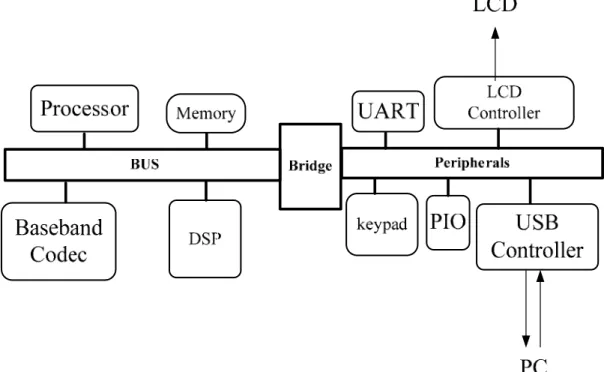
(20) Chapter 2 Background and Challenges. The platform-based architecture includes a processor, memory, communication bus and multiple functional hardware accelerators. It gains more flexibility than ASIC architecture from reusing existence intellectual property (IP), such as digital signal processor (DSP), baseband codec, audio applications accelerator and other functional blocks. The example of platform-based architecture is shown in Fig 2.4. Different IP blocks are added or removed to meet different application. The platform-based architecture provides a common communication bus for convenience to integrated different IP macros quickly. Different systems will be set up as fast as possible. It reduces the design and re-develops effort significantly. One more attractive thing is that these platforms have been set up with a developing baseboard. Many common IP and peripherals on the baseboard will benefit to fast prototyping. The existent OS of the baseboard can reduce the effort of connecting the real applications to development design. Current research such as [12], [13] and [14] are listed in the reference. Thus there are some drawbacks in this architecture. The interface communicate each functional macro increases the overhead of whole system. Besides, the memory bandwidth is limited by the communication bus. These factors decrease the efficiency seriously. In the meantime, the power consumption should be increased when more IP blocks are included. The idle IP macros waste unnecessary power dissipation, too. As discussed above, the platform-based architecture is more flexible and programmable than ASIC design. Thus this architecture is still a task-oriented system. It can not be applied to any application using the same framework.. Fig 2.4 An Example of Platform-Based Architecture -7-.
(21) Chapter 2 Background and Challenges. The reconfigurable architecture, the third design methodology, is similar to platform-based architecture. As shown in Fig 2.5, there are multiple general processing elements in this architecture. These processing elements, or ALU cluster IP blocks, play the key role of operating data stream. A system of reconfigurable architecture is built up with a micro controller, a bus or a network on chip system and a well-hierarchical memory system. One advantage of this kind of architecture is the usages of hardware accelerator IP are reconfigurable. It provides a significant flexibility and programmability for different applications. Another advantage is the applications can be operated concurrently. It means that it provides the ability for parallel operation. Nevertheless, there exist some potential drawbacks in using the design methodology. First, without power management system the power dissipation of unused process elements can not be saved. Second, the reconfigurable architecture could not match the above-introduced characteristic very well since the bandwidth of communication bus is insufficient and data transfer bottleneck encounters between process elements and memory system. The efficient memory hierarchy system is needed to solve the performance degradation. Current research such as [15], [16] and [17] are referenced in the bibliography.. Fig 2.5 A Diagram of Reconfigurable Architecture. -8-.
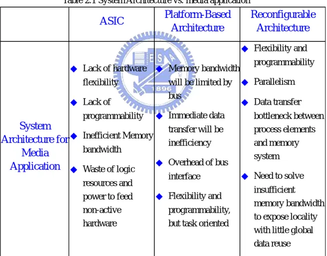
(22) Chapter 2 Background and Challenges. In conclusion, one of these system architectures can be selected to implement the design trading off between pros and cons addressed above. These pros and cons corresponding to characteristics of media applications are summarized in the Table 2.1 listed below. Thus, any one of them adopted alone suffers from some drawbacks and can not meet the application of media processing very well. Consequently, the proposed design will be addressed and discussed in later section. It must resolves these issues.. Table 2.1 System Architecture vs. media application. Platform-Based Architecture. ASIC. Reconfigurable Architecture ◆ Flexibility and. ◆ Lack of hardware ◆ Memory bandwidth. programmability. will be limited by ◆ Parallelism bus ◆ Lack of ◆ Data transfer programmability ◆ Immediate data bottleneck between System transfer will be process elements Architecture for ◆ Inefficient Memory inefficiency and memory bandwidth Media system ◆ Overhead of bus Application ◆ Waste of logic ◆ Need to solve interface resources and insufficient ◆ Flexibility and power to feed memory bandwidth non-active programmability, to expose locality hardware but task oriented with little global data reuse flexibility. -9-.
(23) Chapter 3 Development Roadmap and Proposed Design. CHAPTER. 3. Development Roadmap and Proposed Design Base on the previous two chapters, the background, challenges are addressed. Then the developmental roadmap and the proposed design of this thesis will discussed in this chapter. The first section is the developmental roadmap of this thesis. It introduces the motivation to propose these designs after the issues of Chapter 2 are discussed. Afterwards the streaming programming model and developmental roadmap overcome the issues mentioned above are introduced. The second section is the demonstration of previous design of ALU cluster. Review the architecture of the ALU cluster, the key processing element of ALU cluster intellectual property. Through testing the manufactured chip, the results confirm the correctness of functionality and the architecture is not only feasible but also efficient for media applications. The latter part of the description of this paragraph will be introduced clearly in next chapter. The third part of this chapter is the description of the designed ALU cluster intellectual property. This design is an integration of the improved ALU cluster and the AMBA AHB slave interface. The improved ALU cluster is based on the ALU cluster discussed in previous section. The detail architectures and overview of AMBA AHB slave protocol are introduced in this section. Eventually the forth section of this chapter is the description of the designed floating point operation units for ALU cluster IP. It will bring up an idea to integrate the floating point unit in the ALU cluster IP. The design consideration of the floating point units are described in the section. The details of the design are summarized.. - 10 -.
(24) Chapter 3 Development Roadmap and Proposed Design. 3.1 Developmental Roadmap 3.1.1. Motivation. Issues of programming models and system architectures encountered in modern media processing system are addressed in Section 2.1 and Section 2.2. These drawbacks make the media applications handled inefficiently. The situation is more and more serious when great deals of media applications are applied in portable systems. The media streaming architecture with homogeneous processor cores, a turnkey solution for media applications, is proposed in this thesis. This system intends to provide several cons of processing data stream. First it provides highly parallel computing ability so that multiple processing elements are needed. Performance improvement of media applications is achieved because of exploiting the large available parallelism inherence of media process. Subsequently, the communication bandwidth bottleneck discussed above has to solve. An efficient hierarchy of memory system is needed to expose the characteristic of little global data reuse and high computation to memory access ratio in media applications. Therefore, a reconfigurable hardware accelerator is built as a processing element to form the media streaming architecture with homogeneous processor cores in this thesis.. 3.1.2. Roadmap. As mentioned above in the previous chapter, the conventional programming model is not suitable for these applications. So the stream programming model is adopted in this thesis. We will discuss the stream programming model below. Following the developmental roadmap including system architecture is described in this chapter later.. 3.1.2.1 Stream Programming Model. In the stream programming model, data is aligned in order as a stream. Streams are arbitrary data type. Operations are applied on entire streams. These operations perform computations, stream transfers, loads and stores etc. in the programming model. Nodes which carry out these operations are called kernels. They perform computation, such as a function, to each element of whole data streams. Kernels input - 11 -.
(25) Chapter 3 Development Roadmap and Proposed Design. one or more data streams to operate and output one or more data streams as outputs. These kernels only operate on local data and may not make arbitrary memory references. After introducing streams, operations and kernels in the stream programming model, the structure of the model are depicted in Fig 3.1. As shown in the diagram, the stream programming model handles data by chaining operations together and makes data passing through kernels. Two example of dealing with applications using stream programming model are shown in Fig 3.2 and Fig 3.3 respectively. One is 1024-points complex radix-2 Fast Fourier Transform (FFT), a popular operation in multimedia processing [18]. Another is the example of image processing, the Stereo Depth Extraction, commonly used in modern image and medical diagnosing system [3].. Fig 3.1 Stream Programming model - 12 -.
(26) Chapter 3 Development Roadmap and Proposed Design. Fig 3.2 Example of 1024-points radix-2 Fast Fourier Transform. Fig 3.3 Example of Stereo Depth Extraction Remind the characteristic of the conventional programming model discussed in Section 2.1. Comparison between the stream programming model and the conventional programming model, some obvious pros are revealed when expressing media applications in the stream programming model. Corresponding three features of media process such as little data reuse, high large available parallelism and computation to memory access ratio, Pros are described briefly below. First, multiple kernels exploit the inherent parallelism feature. Second, data streams produced at the end of one kernel will consume at the next kernel makes the programming model fit - 13 -.
(27) Chapter 3 Development Roadmap and Proposed Design. the feature of little data reuse. Finally the high computation to memory access ratio results from the minimization global memory usage in the stream programming model. Features compare between these two programming models are listed in Table 3.1. Table 3.1 Comparison between programming models Conventional Programming Model. Stream Programming Model. Large available parallelism. One central processor unit. Multiple kernels. Little data reuse. Traditional caches are ineffective. Data produced at the end of one kernel will consume at the next kernel. Each element reference the. Minimize global memory. off-chip memory. usage. High computation to memory access ratio. The programming model in this thesis was adopted the stream programming model. Because of the features mentioned above, it is suitable for processing system aimed at multimedia processing applications.. 3.1.2.2 Developmental Roadmap The developmental roadmap proposed in this section provides a suitable solution to process applications to conform the requirement expected. A sketch map of proposed development roadmap is illustrated in Fig 3.4. In this roadmap, five steps are segmented to build the media streaming architecture with homogeneous processor cores. As illustrated in the Fig 3.4, the proposed system gains the advantages from platform-based architecture and reconfigurable architecture. The mixture of system architectures are utilized as the structure of proposed system to overcome the challenge of issues deriving from using these system architectures singly. And the whole processing system provides an efficient processing system to get over issues of programming models and system architectures.. - 14 -.
(28) Chapter 3 Development Roadmap and Proposed Design. ALU cl uster IP. AMBA AHB wrapper Address Generation Unit. Finite State Machine. Synthesized Instruction memory 32. 32. 32. 32. 15. 143. 32 32 14 alu_work. 143 7+3 ALU cl uster. Pc_counter Decoder Load_st ore. 8 10. Cont roller. 32. ALU. 8 IRF. IRF. ALU IRF. MUL. IRF. IRF. IRF. MUL IRF. IRF. DIV IRF. IRF. Scratch P ad. 8. MRAM. ALU cluster IP. AMBA AHB wrapper. Floating Point Unit. Address Generation Unit. Control. A D D /S U B. Instruction Memory 32 32 32 32 14. M UL. D a ta I n pu t. D a t a O u tp u t. 142. ALU cluster IP. Finite State Machine. 32 32 14 alu_work. 142 7+3 ALU cluster. Pc_counter. Controller. Decoder. 32 ALU 32*10 I RF IRF D IV. 32*5 5+4. 32 32. ALU. MUL. MUL. DIV. IRF IRF. IRF IRF. IRF IRF. IRF IRF. 32 32. 32 32. 32 32. 32 32. Scratch Pad. Data memory. Fig 3.4 Development roadmap. Descriptions of these five steps are introduced briefly in this section. First, the leftmost chip photo, implemented in UMC 0.18um CMOS technology, in Fig 3.4 is the prototype 1 of ALU cluster [19] [20] . This is called the first step of proposed developmental roadmap. The chip had been measured and verified. As a processing element, the measurement results demonstrate that the architecture and functionality is suitable and correct for the applications. By the right side of prototype 1, the ALU cluster IP with AMBA AHB interface, the prototype 2, was designed and taped out using TSMC 0.15um CMOS technology. The layout and die photo with package are depicted in the development roadmap respectively. This step verifies the designed ALU cluster IP to be suitable as a reconfigurable hardware accelerator in media applications. In addition to this purpose, the interface obeyed the AHB slave bus provides a common communication bridge between these ALU cluster IPs and micro-controller used to manage whole media streaming system. These features make the proposed prototype 2 have ability as a processing element to be applied in the media streaming system. It is a significant feature of the second step in developmental roadmap.. - 15 -.
(29) Chapter 3 Development Roadmap and Proposed Design. In modern multimedia applications, the floating point operations occupy a large percentage of the computation amount. These floating point operations stand a key role of performance and power consumption in whole applications. A floating point unit is essential in performance improvement if the budget of power consumption and logic resources are agreed. Consequently, an ALU cluster IP supported floating point operation is a requirement. As shown in the middle of Fig 3.4, an ALU cluster IP with floating point supported are introduced. The hard macro of floating point unit is designed and implemented using TSMC 0.18um CMS technology. The combinations of ALU cluster IP and the hard macro provides efficient computing ability to handle floating point operations. It is the third generation in the described developmental roadmap. Following the forth step in Fig 3.4 is discussed in this paragraph. In this step, system integration is preliminary started. An ALU cluster IP with compatible board for logic tile connector will be stacked into the RealView versatile platform baseboard for ARM926EJ-S [21] [22]. In this baseboard, the ALU cluster IP is verified whether the AHB bus interface fits the bus protocol. One ALU cluster IP stacked in the board are also made sure that the IP has the ability as a hardware accelerator integrated with the platform. Finally multiple processing elements, ALU cluster IPs, will be combined with the versatile baseboard to form a media streaming architecture with homogeneous processor cores. The proposed system matches the features of media applications such as large available parallelism, little data reuse and high computation to memory access ratio. Suitable benchmarks are ported into this processing system and compare with each other. These applications include some popular operations in multimedia applications and MIMO-OFDM system. The finite impulse response (FIR) filter system and Fast Fourier Transform (FFT) are selected as benchmarks in media applications. And the key operations of MIMO-OFDM system, such as matrix inversion and Gram-Schmitt process, are selected as benchmarks, too [23]. Adoption of stream programming model and mixture of system architectures make the media streaming system become a turkey solution for modern multimedia processing requirement. Five paragraphs discussed above are introduced the proposed developmental roadmap compendiously. The details of these steps, such as micro architectures, implementation results and etc., are discussed and described in the following sections and chapters respectively. - 16 -.
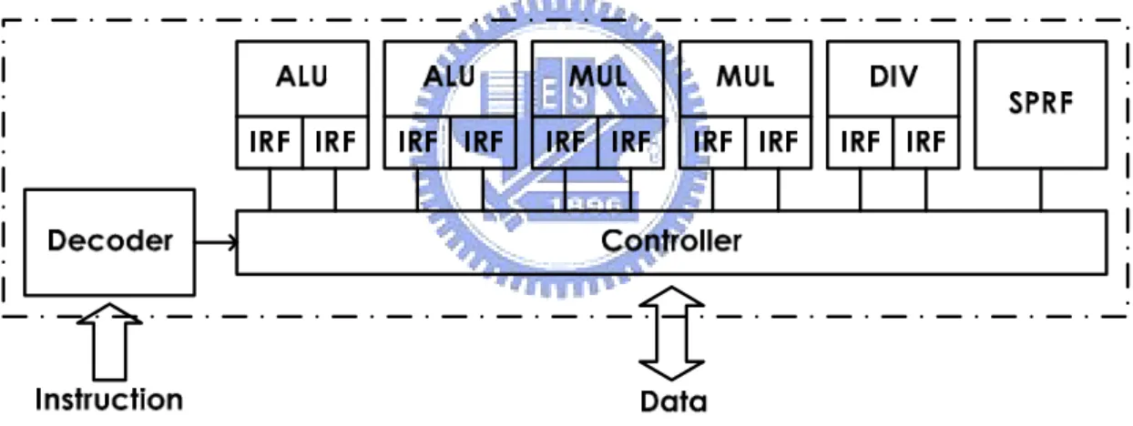
(30) Chapter 3 Development Roadmap and Proposed Design. 3.2 An ALU cluster The briefly description of the previous design, an ALU cluster, included the micro architecture is described. The ALU cluster is called prototype 1 in the above-presented developmental roadmap. It is convincible that it can handle media applications expectedly.. 3.2.1 Micro-Architecture of an ALU cluster As the major part for handling the media processing, an ALU cluster includes five arithmetic units, supporting to process the parallel data concurrently. As shown in Fig 3.5, they are two ALUs, two multipliers and one divider. Large amount of digital signal processing application are suitable for porting in the architecture with mixture of arithmetic units. There is also one scratch pad register file (SPRF), ten banks of intra register file (IRF), a controller and a decoder.. Fig 3.5 Micro-Architecture of ALU cluster There are thirteen instructions can be executed by the ALU, such as ADD, SUB, ABS, AND, OR, XOR, NOT, SLL, SRL, SRA, LT, GT, EQ. The adder and comparator adopted for ALUs are the carry-lookahead architecture with two stage pipeline. Booth encoding architecture was adopted for our four stage pipeline multiplier. This multiplier can carry out multiplication. The last arithmetic unit is the divider. It performs the division operation that gets the quotient and remainder and calculates the square root. The designed divider in an ALU cluster is not the key kernel about performance concerned so that this unit is not pipelined and considered to shrink the logic resource by increasing latencies of operation.. - 17 -.
(31) Chapter 3 Development Roadmap and Proposed Design. As mentioned above, in the ALU cluster there are IRFs embedded for each operation units. These intra register files are local to themselves arithmetic units. The purpose of IRFs is to provide an efficient memory bandwidth for arithmetic units. In other words, these arithmetic units would not waste the precious global memory bandwidth. It acquires required bandwidth from less precious bandwidth of IRFs. Another extra storage element inside the ALU cluster is scratch pad register file. The capabilities of SPRF are as the storage element for commonly used coefficient of applications. The remaining parts of the ALU cluster are the decoder and the controller. The decoder can decode the instructions from off-chip instruction memory and provides control signals needed for ALU cluster. During the execution of an ALU cluster, the controller sequences and issues the decoded instructions to the function units and decides the inputs source, such as IRF, SPRF or data memory. When an ALU cluster operates to read or write, the controller manages the data flowing.. 3.3 An ALU cluster Intellectual Property In this section, an ALU cluster Intellectual Property (IP) is designed and the architecture is also discussed. It is the prototype 2 mentioned in the roadmap presented in previous section [24]. As mentioned in previous chapter, there is an AMBA AHB wrapper in the ALU cluster IP. First the AMBA AHB protocol will be described in the following paragraph. Then the micro architecture of an ALU cluster IP will be presented and discussed in the last part of this section.. 3.3.1 Overview of AMBA The Advanced Microcontroller Bus Architecture (AMBA) specification defines an on-chip communications standard for designing high-performance embedded microcontrollers [25]. There are three buses defined in this specification. They are Advanced High-performance Bus (AHB), Advanced System Bus (ASB), and Advanced Peripheral Bus (APB). These bus protocols are used in different applications. For example, the AHB are used as the high-performance system backbone bus. It is for high-performance and high clock frequency system modules. It provides the efficient connection of processors, on-chip memories and off-chip external memory interfaces with low-power peripheral macrocell functions. The ASB is also for high-performance system modules. It is suitable for system bus that the high-performance features of AHB are not required. It also supports the efficient - 18 -.
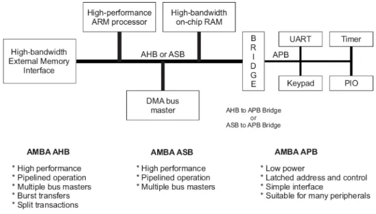
(32) Chapter 3 Development Roadmap and Proposed Design. connection of processors, on-chip memories and off-chip external memory interfaces with low-power peripheral macrocell functions the same as AHB. Finally, the APB optimized with minimal power consumption and interface complexity is used for peripherals. APB can be used in conjunction with either version of the system bus. Four key requirements are satisfied by AMBA specification. They are right-first-time, technology-independent, modular system design and minimization of the silicon infrastructure. The system obeyed AMBA protocol could facilitate the right-first-time development of embedded microcontroller products with one or more CPUs or signal processors. The specification is technology-independent and ensures that highly reusable peripheral and system macrocells can be migrated across a diverse range of IC processes and be appropriate for full-custom, standard cell and gate array technologies. It also improves processor independence, providing a development roadmap for advanced cached CPU cores and the development of peripheral libraries to encourage modular system design. The system using AMBA protocol can be minimized the silicon infrastructure required to support efficient on-chip and off-chip communication for both operation and manufacturing test. A typical AMBA-based microcontroller is composed of a high-performance system backbone bus (AMBA AHB or AMBA ASB) which is able to sustain the external memory bandwidth, on which the CPU, on-chip memory and other Direct Memory Access (DMA) device reside. The diagram of AMBA-based system is shown in Fig 3.6. The backbone bus of whole system has ability to provide a high-bandwidth interface between elements involved in the majority of transfers. APB, a lower bandwidth bus, is located on the high-performance bus by the bridge. Most of the peripheral devices in the AMBA-based system are located. The features of AHB, ASB and APB are listed in Fig 3.6. As shown below in this figure, AHB is suitable for high performance, pipelined operation, multiple bus masters, and burst transformation and split transactions. Compare with AHB, ASB is lack of the ability to burst transformation and split transactions. The simple interface is adopted by APB. It latches address and control signal to save power. Thus it is suitable for many peripherals. The difference between APB and AHB or ASB is that AHB and ASB are able to wait the transfer during it is not ready whether the wait situation is from on-chip bus or itself. APB must response the transaction immediately.. - 19 -.
(33) Chapter 3 Development Roadmap and Proposed Design. Fig 3.6 Diagram of AMBA-based system. 3.3.1.1 Introduction of AMBA AHB The AMBA AHB is a new generation bus intended to address the requirements of high-performance synthesizable designs. It sits above the APB and implements the features required for high-performance, high clock frequency system, including split transactions, burst transfers, single cycle bus master handover, single clock edge operation, non-tristate implementation and wider data bus configurations. The AMBA AHB system is designed with the following components, including AHB bus master, slave, decoder and arbiter. These typical components are described briefly below. The AHB master starts an AMBA AHB transfer by driving address and control signals. They provide information which the AHB slave needed. Exact one bus master is allowed to actively use the bus at any one time. This component is the most complex bus interface in an AMBA system. Usually the designer would use existence bus master rather than concerned with the details in the bus master interface. The AHB bus slave responds a write or read operation. All signals required for the transfer, such as the address and control information, will be generated by the bus master. The bus slave signals back to the active master the success, failure or waiting of the data transfer.. The AHB bus decoder is used to perform a centralized address decoding function, which improves the portability of peripherals, by making them independent of the - 20 -.
(34) Chapter 3 Development Roadmap and Proposed Design. system memory map. It is used to decode the address of each transfer and provide a select signal for the slave that is involved in the transfer. Finally the AHB bus arbiter will be described. The AHB arbiter is used to control which master has access to the bus. It ensures that only one bus master is allowed to initiate data transfers at a time. The arbiter uses a prioritization scheme to decide which bus master is currently the highest priority master requesting the bus. The detail of the priority scheme is not specified and is defined for each application. Some details of AHB interface, such as bus interconnection, signals for AHB slaves, basic transfer, transfer type, address decoding and burst operation will be presented in the following sub sections. The reaming details will be described in the AMBA specification.. 3.3.1.2 Bus Interconnection The diagram of AMBA AHB interconnection is shown in Fig 3.7. As illustrated in the diagram, this protocol is designed to be used with a central multiplexer interconnection scheme. The scheme makes all bus master drive out the address and control signals indicating the transfer they intend to perform. Then the arbiter obeyed the prior policy determines which master is able to route its address and control signals to all of the slaves. There is also a central decoder in Fig 3.7. It is used to control the read data and response signal multiplexer to response appropriate signals from the slave to the master which involved in the transfer.. - 21 -.
(35) Chapter 3 Development Roadmap and Proposed Design. Fig 3.7 Diagram of AMBA AHB interconnection. 3.3.1.3 Signals for the protocol of AMBA AHB slave The signals using in AHB slave protocol are shown in Fig 3.8, which is the diagram of AHB slave interface. These signals are briefly described in the following paragraph.. - 22 -.
(36) Chapter 3 Development Roadmap and Proposed Design. Fig 3.8 Diagram of AHB slave interface. The input signals are classified into six groups such as select, address and control, data, reset, clock and split capable signals. The select signal, HSELx, is from decoder and indicates that the current transfer is intended for the selected slave. The address and control signals such as HADDR, HWRITE, HTRANS, HSIZE and HBURST are from master to slave. HADDR is the system address bus. HWRITE indicates that the transfer is reading operation or writing operation. HTRANS indicates the type of current transfer. HSIZE shows the size of the transfer and HBURST shows the burst type of operations in the transfer. The data signal, HWDATA, is form master and used to transfer data during write operations. The reset and clock signal are HRESETn and HCLK respectively. The signals shown in the bottom of Fig 3.8 are from arbiter and used to support the split transactions.. There are four output signals. They are HREADY, HRESP, HRDATA and HSPLITx. The HREADY indicates a transfer has finished on the bus and the HRESP provides additional information on the status of a transfer. Above-mentioned signals - 23 -.
(37) Chapter 3 Development Roadmap and Proposed Design. are called transfer response signal group. The HRDATA is used to transfer data from slaves to masters during read operations. The last output signal is HSPLITx, which is used for split completion request.. 3.3.1.4. Basic Transfer. The basic transfer of AHB protocol is composed of two phases. They are address phase and data phase. An example of simple transfer is shown in Fig 3.9. As illustrate in the figure, the address phase only requires one cycle but the data phase may require several cycles. The necessary signals needed for the basic transfer are HCLK, HADDR, control, HWDATA. The transfers will response the HREADY, HRDATA and HRESP. The figure demonstrates how the address and data phases of the transfer during different clock periods. The address phase always occurs during the data phase of previous transfer. The above-mentioned situation of overlapping is based on the pipelined nature of the bus and allows for high performance operations. The logic high of HREADY represents the transfer is ready to be finished and logic low shows that the transfer is needed to be extended. The example of the transfer needed to be extended is shown in Fig 3.10. The address phase is the same as Fig 3.9. Thus the data phase shown in Fig 3.10 is extended with two cycles because the transfer is not ready to be completed by means of signaling the HREADY logic low. This may result from both master and slave depends on the transfer type. It will be introduced in the following section.. Fig 3.9 An example of simple transfer - 24 -.
(38) Chapter 3 Development Roadmap and Proposed Design. Fig 3.10 The example of the transfer extended. 3.3.1.5 Transfer Type The transfers of AMBA AHB are classified into four different transfer types. The HTRANS signals will be used to indicate the type of transfer. The two bits signal represents IDLE, BUSY, NONSEQ and SEQ by 00, 01, 10 and 11 respectively. These transfer types will be introduced below. The IDLE state indicates no data transfer is required and is used when a bus master is granted the bus but does not intend to perform a data transfer. The bus slaves must always provide a zero wait state OKAY response to IDLE transfers and the transfer should be ignored by the slave. The BUSY transfer type indicates the bus master is continuing with a burst of transfers, but the next transfer cannot take place immediately. This transfer type allows bus masters to insert IDLE cycles in the middle of bursts of transfer. When a master uses the BUSY transfer type the address and control signals must reflect the next transfer in the burst. The transfer should be ignored by the slave. Slaves must always provide a zero wait state OKAY response, in the same way that they respond to IDLE transfers. The NONSEQ transfer type is used to indicate the first transfer of a burst or a single transfer. The necessary information such as address and control signals are - 25 -.
(39) Chapter 3 Development Roadmap and Proposed Design. unrelated to the previous transfer. In AMBA AHB specification, a single transfer on the bus is treated as the first one of a burst therefore the transfer type is NONSEQ too. The last one transfer type is SEQ. This type indicates the remaining transfers in a burst. The address needed is related to the previous transfer and it is equal to the address of the previous transfer plus the size in the incrementing burst. But in the situation of wrapping burst, the address of the transfer wraps at the address boundary equal to the size multiplied by the number of beats in the transfer. In addition, the control information is identical to the previous transfer.. 3.3.1.6 Address Decoding The select signal, HSELx, will be provided by an address decoder shown in Fig 3.11 for each slave on the bus. The select signal is a combinatorial decode of the high-order address signals and simple address decoding schemes are encouraged to avoid complex decode logic and to be suitable for high-performance operations. A slave only samples the address and control signals and HSELX when HREADY is logic HIGH. It is indicates that the current transfer is completing. Under certain situation it is possible that HSELx will be asserted when HREADY is logic LOW, but the selected slave will have changed by the time the current transfer completes. The minimum address space can be allocated to a single slave is 1kB. All bus masters are designed such that they will not perform incrementing transfer over a 1kB boundary, thus ensuring that a burst never crosses an address decode boundary.. Fig 3.11 Slave Selected Signal - 26 -.
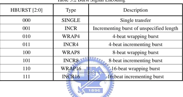
(40) Chapter 3 Development Roadmap and Proposed Design. 3.3.1.7 Burst Operation There are two kinds of bursts of the burst operations supported in the AMBA AHB protocol. They are incrementing and wrapping burst modes. Four, eight and sixteen-beat bursts are defined in AHB protocol. The burst information is identified by the signal HBURST. It decides the burst modes and beat number. The relationship between signal and type is listed in Table 3.2. There are eight types defined in this table. Table 3.2 Burst Signal Encoding HBURST [2:0]. Type. Description. 000. SINGLE. Single transfer. 001. INCR. Incrementing burst of unspecified length. 010. WRAP4. 4-beat wrapping burst. 011. INCR4. 4-beat incrementing burst. 100. WRAP8. 8-beat wrapping burst. 101. INCR8. 8-beat incrementing burst. 110. WRAP16. 16-beat wrapping burst. 111. INCR16. 16-beat incrementing burst. The address accessing of each transfer in the burst of the incrementing burst mode is sequential and an increment of the previous address. In the wrapping burst mode, if the start address of the transfer is not aligned to the total number of bytes in the burst (size x beats) then the address of the transfer in the burst will wrap when the boundary is reached. For example, a four-beat wrapping burst of word accesses will wrap at 16-byte boundaries. Therefore, if the start address of the transfer is 0x34, then it consists of four transfers to addresses 0x34, 0x38, 0x3C and 0x30. It will wrap the address back when the boundary is reached. As description it will wrap back to 0x30.. Bursts must not cross a 1kB address boundary. It is important that masters do not attempt to start a fixed-length incrementing burst which would cause this boundary to be crossed. It means that an incrementing burst can be of any length, but the upper limit is set by the fact that the address must not cross a 1kB boundary. The signal, HSIZE, is used to control the transfer size. It supports eight different sizes such as 8, 16, 32, 64, 128, 256, 512 and 1024 bits. Finally the endian policy defined in this protocol is shown in Table 3.3 and Table 3.4. They are big-endian and little-endian - 27 -.
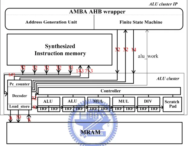
(41) Chapter 3 Development Roadmap and Proposed Design. respectively. The designer only needs to obey one of the endian policies and makes whole systems consistently. Table 3.3 Active Byte Lanes for a 32 bits big endian data bus Transfer size. Address offset. Data [31:24]. Data [23:16]. Data [15:8]. Data [7:0]. Word Halfword Halfword Byte Byte Byte Byte. 0 0 2 0 1 2 3. ˇ ˇ ˇ. ˇ ˇ -. ˇ ˇ. ˇ -. ˇ. ˇ ˇ -. -. -. -. ˇ. Table 3.4 Active Byte Lanes for a 32 bits little endian data bus Transfer size. Address offset. Data [31:24]. Data [23:16]. Data [15:8]. Data [7:0]. Word Halfword Halfword Byte Byte Byte Byte. 0 0 2 0 1 2 3. ˇ. ˇ. ˇ. ˇ. ˇ ˇ. ˇ ˇ. ˇ. ˇ. ˇ. ˇ. -. -. -. 3.3.2 Micro-Architecture of an ALU cluster Intellectual Property The proposed ALU cluster Intellectual Property (IP) id described in this section. The detail architecture is shown in Fig 3.12. As illustrated in Fig 3.12, four main blocks composed of this design are AMBA AHB wrapper, ALU cluster, instruction and data memory. The instruction and data memory are used to feed the data and instruction required for operation into functional units.. - 28 -.
(42) Chapter 3 Development Roadmap and Proposed Design. Fig 3.12 The Proposed ALU Cluster IP Architecture The major part for dealing the media applications is an ALU cluster as description in Section 3.2. The arithmetic units and internal storages part of the ALU cluster in this ALU cluster IP is the same as the one introduced in Section 3.2.1. However, the control and internal storages are improved in this designed ALU cluster IP. The ALU cluster in this designed is improved the ability to reading source and writing destination. It makes all banks of data and instruction memory expose to the AMBA bus. It means that these memory banks can be accessed directly from AMBA bus through the AMBA AHB wrapper which will be introduced later. In addition, the better performance is exploited by shortening reading cycles. In the original ALU cluster, the reading must take four cycles to access one burst reading operation. However, in the improved ALU cluster, the reading operation takes two cycle latencies in burst reading and then the data is read sequentially in every cycle. The ALU cluster IP must has the ability to execute when the AMBA bus is granted by other masters so that the ALU cluster needs a functional block to feed address to the instruction memory automatically. As illustrates in Fig 3.12, the Pc_counter is used to process this job. It will increase the program counter by one in - 29 -.
(43) Chapter 3 Development Roadmap and Proposed Design. every clock cycle. The decoder will compare the value of program counter with the end value of Pc_counter every cycle to check if the ALU cluster finishes the job. If the job is completed, the alu_work signal is activated to send information to the wrapper. In the alu_work signal is inactive, the IP can not be accessed and returns RETRY signal response to AMBA bus. Besides, one special input signal combination can clear the end value of Pc_counter in the decoder and force the IP to stop execution. The special mechanism is designed in order to avoiding the possibility of the deadlock occurrence. Another key component of ALU cluster IP is AMBA AHB wrapper. It will be discussed in this paragraph. The wrapper interface conforms to Advanced Microcontroller Bus Architecture (AMBA) Advanced High-performance Bus (AHB) protocol described in Section 3.3.1. It provides a common interface to integrate the proposed design with ARM versatile baseboard and form a media processing system. A finite state machine (FSM) and an address generation unit (AGU) are composed of the architecture of proposed wrapper. The finite state machine of proposed wrapper is used to control the states and response the request of AMBA bus. It provides the communication capability between AHB slave bus and the ALU cluster inside proposed IP. It receives signals from AMBA bus and activates the ALU cluster to response. The FSM also controls the address generation unit to produce necessary address for the ALU cluster, whether operating in incrementing mode or wrapping mode of burst operation. This FSM is designed with six states. They are Idle, Accessible, ALU_Work, Un-readable Wait, Un-writable Wait and Error. As shown in Fig 3.13, the state diagram of the finite state machine, the FSM will stay in the Idle state while the IP is not accessible or the operation of ALU cluster is finished. Whether IP has done the work or suffers from some error, it returns back to the Idle state. In this state, the wrapper will be ready to receive signals from bus and prepare next operation. It will go to other starts while the bus is granted and the IP will be accessed or the ALU cluster is activated. The condition of going to other state is only when the HTRANS signal equals to NONSEQ. If the NONSEQ is encountered, it identifies which operation of the IP is requested by HWRITE then the FSM will move to the target state.. - 30 -.
(44) Chapter 3 Development Roadmap and Proposed Design. Fig 3.13 The state diagram of the finite state machine In the next state, Accessible state, the IP is accessible. When the HTRANS signal is equal to NONSEQ and the HWRITE signal is logic high, it will directly move to this state. There is a control signal to identify the different types of accessing whether incrementing mode or wrapping mode is utilized in the burst transformation while staying this state. One type is that the IP is accessed with different address with the HTRANS signal equals to NONSEQ. Another one is that the IP is accessed continuously with the address of the previous access in wrapping or incrementing mode in the burst transformation. Three conditions are forced the FSM to other states. These cases are access is finished, ready to read but data is not ready and busy to write. The states are moved to Idle, Un-readable Wait and Un-writable Wait. The later two of the above-mentioned states are addressed below. The Un-readable Wait state exists because of the two necessary cycle of reading data latency. One of two paths makes the FSM enter the Un-readable state is when the FSM is in the Idle state and the HTRANS signal is NONSEQ and the HWRITE signal is logic low. It presents the IP is being read. The first reading operation needs two cycles to prepare necessary data so it must be in this state until the data is ready. Then it will enter the Accessible state to perform the following reading request. Another one of two paths is from Accessible state to Un-readable Wait state because of the necessary latencies. In addition, when the IP is being written data in burst mode of wrapping or incrementing type thus the TRANS signal of AHB slave is changed to - 31 -.
數據

+7

相關文件
You are given the wavelength and total energy of a light pulse and asked to find the number of photons it
Reading Task 6: Genre Structure and Language Features. • Now let’s look at how language features (e.g. sentence patterns) are connected to the structure
好了既然 Z[x] 中的 ideal 不一定是 principle ideal 那麼我們就不能學 Proposition 7.2.11 的方法得到 Z[x] 中的 irreducible element 就是 prime element 了..
Wang, Solving pseudomonotone variational inequalities and pseudocon- vex optimization problems using the projection neural network, IEEE Transactions on Neural Networks 17
volume suppressed mass: (TeV) 2 /M P ∼ 10 −4 eV → mm range can be experimentally tested for any number of extra dimensions - Light U(1) gauge bosons: no derivative couplings. =>
For pedagogical purposes, let us start consideration from a simple one-dimensional (1D) system, where electrons are confined to a chain parallel to the x axis. As it is well known
The observed small neutrino masses strongly suggest the presence of super heavy Majorana neutrinos N. Out-of-thermal equilibrium processes may be easily realized around the
Define instead the imaginary.. potential, magnetic field, lattice…) Dirac-BdG Hamiltonian:. with small, and matrix
