I
NTRODUCTION
Future optical wavelength-division multiplexing (WDM) [1] networks are expected to flexibly and cost-effectively satisfy a multitude of appli-cations with diverse quality of service (QoS) requirements. Such facts bring about the need to exploit the optical packet switching (OPS) [1, 2] paradigm that advocates efficient sharing of wavelength channels among multiple connec-tions. Nevertheless, OPS systems still face sever-al technologicsever-al limitations, such as opticsever-al random access memory (RAM) and optical sig-nal processing. Hence, the OPS system we study
in this work employs almost-all optical switches in which packet payloads remain in the optical domain, and only the control headers are pro-cessed electronically. A general OPS system con-sists of three basic components that are crucial to the performance and economy of the system: the space switch, optical buffer, and wavelength converter [3]. While the space switch operates as a main subsystem to switch incoming packets to their destined output ports, the optical buffer and wavelength converter help resolve con-tentions in time and wavelength dimensions, respectively.
First, space switches can be categorized as being non-blocking or blocking [4, 5]. Non-block-ing switches are mostly used for traditional elec-tronic circuit switching systems. Non-blocking switches, such as the crossbar matrix network and Cantor network, can always construct a new con-nection between the input and output ports with-out altering other connections already in the switches. However, these non-blocking switches are less scalable and economically infeasible in the optical domain due to using a large number of switching elements. There is another type of non-blocking switches, called rearrangeable switches (e.g., Benes network), which route new input-output connections by rearranging all other existing connections. Rearrangeable switches are more scalable than their non-blocking counter-parts, but they nevertheless require more compli-cated scheduling (or rearranging) algorithms, causing the switch processing to slow down. For the second category, blocking switches, Banyan switches enable self-routing and require the least number of switching elements. It is the most scal-able and economic architecture, but at the cost of reduced throughput due to the occurrence of internal blocking [4]. In this work, we aim at achieving high scalability of switches by exploiting a set of smaller space switches that can be of any above architecture type.
Second, optical buffers are currently achieved by ether increasing the light path distance via
A
BSTRACT
Optical packet switching has been considered a prominent paradigm for future WDM net-works to efficiently support a multitude of appli-cations with diverse quality of service requirements. In this article we present the architectural design and experimental demon-stration of a 10 Gb/s QoS optical packet switch-ing system (QOPSS) for WDM networks. It embodies a set of many-to-one space switches, each of which handles the switching solely for a cluster of wavelengths. With the cluster-based optical switch design, QOPSS trades off limited statistical multiplexing gains for higher system scalability. By many-to-one, multiple packets that are carried by different internal wavelengths are scheduled to switch to the same output port but receive different delays afterward. QOPSS adopts downsized feed-forward optical buffers, yielding drastic reduction in packet loss proba-bility in an economical manner. Significantly, through using four-wave-mixing wavelength con-verters at the output section, QOPSS permits optical packet preemption, thus achieving effec-tual QoS differentiation. The article presents both simulation and experimental testbed results to demonstrate the feasibility and superior pack-et loss/QoS performance of the system.
T
OPICS IN
O
PTICAL
C
OMMUNICATIONS
Maria C. Yuang, National Chiao Tung University
Yu-Min Lin, Industrial Technology Research Institute
Ju-Lin Shih, Po-Lung Tien, and Jason J. Chen, National Chiao Tung University
Steven S. W. Lee, National Chung Cheng University
Shih-Hsuan Lin, National Chiao Tung University
A QoS Optical Packet Switching System:
Architectural Design and
fiber delay lines (FDLs), or slowing down the light velocity. The slow-light technologies [6, 7] have been shown to have limited capacity and delay-bandwidth product [7]. For this reason, the FDL-based optical buffer remains a more practi-cal option. The FDL-based optipracti-cal buffer can be applied under various buffering strategies [8]: input buffering, output buffering, and shared buffering. While input (output) buffering has a separate buffer for each input (output) port, shared buffering allows buffers to be shared among multiple inputs and/or outputs. There are two major FDL-based buffering structures: feed-back or feed-forward [9]. The feedfeed-back structure can support dynamic buffering durations at the expense of additional hardware to maintain sig-nal quality [10–12]. By contrast, the feed-forward FDL structure only supports fixed buffering durations [13] but ensures better signal quality. Thus, the feed-forward structure is generally preferred over its feedback-based counterpart.
Third, tunable optical wavelength converters (TOWCs) offer an alternative to contention res-olution in the space (wavelength) dimension. Because TOWCs impose a high cost penalty on OPS systems, much research work has focused on the reduction of the cost via the sharing of TOWCs [14] and/or the use of limited-range TOWCs [15]. In general, TOWCs can be real-ized by three key methods [15]: cross-gain modu-lation (XGM), cross-phase modumodu-lation (XPM) [16], and four-wave mixing (FWM) [17]. By tak-ing advantage of the gain saturation phe-nomenon of the semiconductor optical amplifier (SOA), the XGM scheme inversely transfers the modulation of the input wavelength’s amplitude to that of the output wavelength’s amplitude. The scheme is simple and polarization-insensi-tive due to the use of the polarization-insensipolarization-insensi-tive SOA. However, its major drawback is the reduc-tion of the extincreduc-tion ratio for up-converted sig-nals. In the XPM scheme, the refractive index of one arm of the SOA-integrated interferometer is modulated in accordance with the source signal’s intensity. As a result, the two-arm XPM convert-er genconvert-erates eithconvert-er a constructive or destructive interference effect on the target wavelength. Such an effect entails the encoding of the source bitstream onto the target wavelength. The scheme outperforms XGM in the extinction ratio and conversion range at the cost of more complex components. Nevertheless, XPM con-verters are limited to amplitude modulation for-mats and require accurate control of the SOA bias [15]. Finally, an FWM converter is based on the four-wave-mixing nonlinear effect of SOA for converting wavelengths. The FWM scheme is attractive because of being able to convert a group of wavelengths simultaneously, and trans-parent to the modulation format and data rate. With the method proposed in [17], the FWM converter can attain high conversion efficiency even for large conversion ranges.
In this article we present the architectural design and experimental demonstration of a 10 Gb/s QoS-enabled optical packet switching sys-tem (QOPSS) for WDM networks. QOPSS boasts three crucial features. First, it embodies a set of many-to-one space switches, each of which handles the switching solely for a cluster of
wavelengths. Such cluster-based optical switch design aims at trading off limited statistical mul-tiplexing gains for higher system scalability. Sec-ond, QOPSS adopts downsized feed-forward optical buffers that are applied based on the out-put and shared buffering strategies. Such a design, as shown herein, yields drastic reduction in packet loss probability (PLP) in an economi-cal fashion. Third, by incorporating FWM con-verters at the output section, QOPSS supports
optical packet preemption by permitting
higher-priority packets to preempt lower-higher-priority pack-ets already in the delay lines, thereby achieving effectual QoS differentiation. Finally, the article presents both simulation and experimental testbed results to demonstrate the viability and superior packet loss/QoS performance of the sys-tem.
The remainder of this article is organized as follows. In the next section we present the gen-eral architecture of QOPSS. The operations of packet switching, buffering, and preemption are detailed. We then display via simulation results the packet loss and QoS performance of QOPSS. We then delineate the experimental testbed sys-tem setup, and demonstrate the performance of system components and the feasibility of QOPSS. Finally, concluding remarks are given in the final section.
QOPSS: S
YSTEM
A
RCHITECTURE
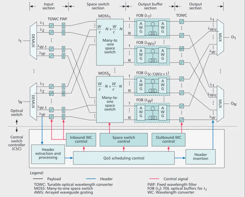
QOPSS is a synchronous system that supports fixed-size packets of different priorities. As shown in Fig. 1, it consists of two parts: the opti-cal switch and the central switch controller (CSC). First, before entering the optical switch, all packets are required to be time-aligned (syn-chronous). Such synchronization can be imple-mented by the use of cascaded switched fiber delay lines [18, 19]. While each packet header that carries the label and QoS (priority) infor-mation is electronically processed by the CSC, the payload travels within the switch all-optical-ly. The header is modulated with its payload based on the superimposed amplitude shift key-ing (SASK) technique [20].The optical switch consists of four sections: input, many-to-one space switch (MOSS), output buffer, and output sections. In the input section there are N input fibers, each carrying W wave-lengths. After demultiplexing, for each packet a TOWC converts its input wavelength to an inter-nal wavelength that corresponds to a free space in the output optical buffer. In the MOSS sec-tion there are c independent space switches that are responsible for switching c clusters of wave-lengths, respectively. Each space switch is a broadcast-and-select-based switch. Specifically, space switch SSkswitches W/c input wavelengths
(from λ(k–1)W/c+1to λkW/c), for each of N fibers,
to W/c output wavelengths (from λ(k–1)W/c+1to λkW/c), lending the switch size to N ⋅ (W/c) × N ⋅
(W/c), where c is the total number of clusters in the switch. Notice that by many-to-one, multiple packets coming from different inlets that are scheduled to depart from the system through the same output wavelength and fiber but receiving different delays are carried by different internal wavelengths and switched to the same outlet.
A general OPS system consists of
three basic components that are
crucial to the performance and
economy of the system: the space
switch, optical buffer, and
wave-length converter. While the space switch operates as a
main subsystem to switch incoming
packets to their destined output ports, the optical buffer and wave-length converter help
resolve contentions in time and wave-length dimensions,
The output buffer section contains W FDL optical buffers (FOBs) for W wavelengths, respectively. Each FOB is shared by all N output ports. An FOB is composed of a pair of arrayed waveguide gratings (AWGs) and F optical FDLs connecting the AWGs, resulting in a total of BF buffer positions, where BF = (F – 1) × M, and M is the number of internal wavelengths. It is worth noting that a packet entering the FOB at the ith input port will exit the buffer from the ith output port after receiving a certain delay time deter-mined by the internal wavelength [12]. Thus, for any FOB, an internal wavelength of a packet uniquely determines the delay received by the packet. In the output section there are N × W FWM-based TOWCs and N output fibers, each carrying W wavelengths. At each output port of the second AWG of an FOB, multiple packets that are carried by different internal wavelengths may have been scheduled to exit from the output port at the same time. This only occurs as a result of an attempt to preempt a lower-priority packet that has already been in the delay line by a higher-priority packet observing unavailable buffer space upon arrival. The preemption is
accomplished by tuning the FWM converter in such a way that, upon converting the group of wavelengths, the target wavelength for the high-priority packet falls into the output wavelength. Then all other packets outside of the output wavelength are automatically dropped after the multiplexing.
The CSC is composed of six modules. The headers of newly arriving packets are first demodulated [20] by the header extraction and processing module. Their label and priority information is passed to the QoS scheduling control module. The module performs QoS scheduling by determining the destined wave-length and the internal wavewave-length correspond-ing to the buffer delay that each packet is gocorrespond-ing to receive. Basically, packets are sequentially scheduled based on the following simple algo-rithm, which adopts priority upon arrival with preemption (PA+P): high-priority packets receive lower delay than low-priority packets; and if the system is full, a newly arriving high-priority packet can preempt the low-high-priority packet in the buffer receiving the least delay. Due to the clustering-based architecture design,
Figure 1. QOPSS: system architecture.
Header extraction and
processing
Legend:
Payload
TOWC: Tunable optical wavelength converter MOSS: Many-to-one space switch
AWG: Arrayed waveguide grating
FWF: Fixed wavelength filter FOB (λi): FDL optical buffers for λi WC: Wavelength converter Header insertion Inbound WC control Outbound WC control Space switch control
QoS scheduling control Optical switch Central switch controller (CSC) MOSS1 I1 O1 TOWC FWF Input section Space switch section λ1 λ1 λW/c λW DEMUX MUX ON MUX λ2 λW-1 λW Output buffer section Output section IN λ1 DEMUX λ2 λW-1 λW TOWC A W G FOB (λ1) 1 N A W G λ1 λW/c λW
Many-to-one space switch MOSSc W · N × W · N c c FOB (λW/c) 1 N A W G FOB (λ(c-1)W/c+1) 1 N A W G A W G FOB (λW) 1 N A W G
Header Control signal
Many-to -one space switch W · N × W · N c c A W G A W G
packet scheduling for all clusters can be per-formed independently and in parallel. The com-putational complexity of the scheduling algorithm is polynomially bounded and can be derived as follows. Given that there are at most
N(W/c) packets in each cluster, and each packet
is sequentially assigned with one output wave-length (out of W/c wavewave-lengths) and one fiber delay line/internal wavelength in the FOB (out of F FDL’s), the computational complexity is thus O(N(W/c)2F). Regarding scheduling algo-rithms, in another line of our work in which the broadcast-and-select space switches are econom-ically replaced by pseudo-Banyan space switches, a near-optimal packet scheduling algorithm [21] was proposed to solve the NP-complete packet scheduling problem.
The QoS control module then passes the des-tined wavelength/output port, internal wave-length, and preemption information to the space switch (SS) control, inbound wavelength convert-er (WC) control, and outbound WC control modules, respectively. Finally, the header inser-tion module inserts and combines the new head-er with its payload before exiting from the optical switch.
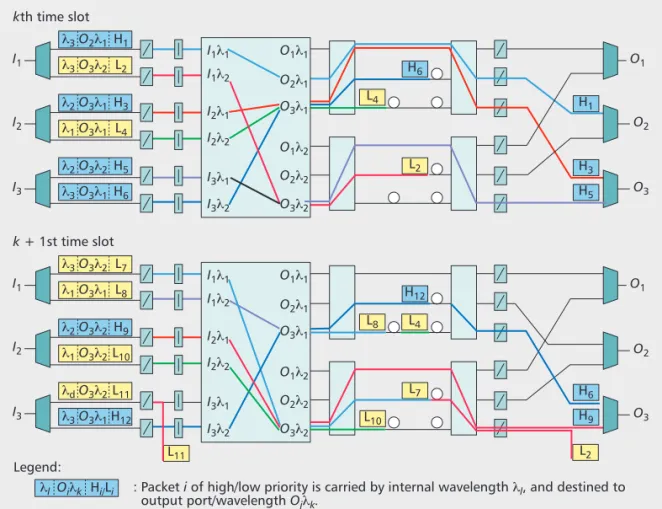
We now illustrate the packet switching, buffering, and preemption operations via an example, as shown in Fig. 2. In this example the system has three input/output ports and two input/output wavelengths. It uses three internal wavelengths corresponding to three FDLs of no, one-slot, and two-slot delays, respectively. There are six packets that arrive at each of the kth and
k + 1st time slots, of which six are of high
prior-ity (H) and six of low priorprior-ity (L). At the kth slot, high-priority packets H1, H3, and H5are switched directly to their destined output ports without experiencing any delay. The remaining three packets (L2, L4, and H6) are switched and buffered in the FDLs, as shown in the figure. For example, L2is destined to O3λ2, which is occupied by H5and becomes unavailable. The system then tags L2with internal wavelength λ3 so that the packet can be inserted to the delay line with one-slot delay. At the k + 1st slot, packet H9 arrives and is scheduled to pass through the system by preempting L2in the buffer due to having a full buffer. To this end, H9is tagged with interval wavelength λ2and departs from the buffer simultaneously with L2, with the result that L2is dropped before multi-plexing. Besides, due to unavailable buffer space, L11is immediately discarded before entering the system.
PLP
AND
Q
O
S D
IFFERENTIATION
:
S
IMULATION
R
ESULTS
Recall that each MOSS is a broadcast-and-select non-blocking switch; packets are only lost due to unavailable optical buffers. In this section we examine the PLP and QoS performance of QOPSS under different numbers of wavelengths (per cluster), numbers of FDLs, and traffic burstiness via simulation results. We carried out a time-based simulation implemented in C++. Simulation terminated after reaching a 95 per-cent confidence interval. In the simulation each
Figure 2. Packet switching, buffering, and preemption - an example.
Legend:
: Packet i of high/low priority is carried by internal wavelength λl, and destined to output port/wavelength Ojλk. kth time slot λ3O2λ1 I1λ1 I1λ2 I2λ1 I2λ2 I3λ1 I3λ2 O1λ1 H6 H1 H3 H5 L4 O2λ1 O3λ1 O1λ2 O2λ2 O3λ2 H1 I1 O1 λl Oiλk Hi/Li λ3O3λ2 L2 λ2O3λ1 H3 I2 λ 1O3λ1 L4 λ2O3λ2 H5 I3 λ3O3λ1 H6 O2 O3 L2 k + 1st time slot λ3O3λ2 I1λ1 I1λ2 I2λ1 I2λ2 I3λ1 I3λ2 O1λ1 H12 H6 H9 L8 L4 O2λ1 O3λ1 O1λ2 O2λ2 O3λ2 L7 I1 λ1O3λ1 L8 O1 λ2O3λ2 H9 I2 λ 1O3λ2L10 λdO3λ2L11 I3 λ3O3λ1H12 O3 L7 L2 L10 L11 O2 The preemption is accomplished by tuning the FWM converter in such a
way that, upon converting the group
of wavelengths, the target wavelength for the high-priority packet falls into the output wavelength. Then, all other packets outside of
the output wave-length are
automati-cally dropped after the MUX.
MOSS handles a total of 10 input/output ports and W wavelengths, resulting in 10W connec-tions processed by the MOSS. Each connection is given an identical load of traffic generated fol-lowing a two-state interrupted Bernoulli process (IBP) [22] for modeling busty traffic. The two states are the 1 and 0 states, which correspond to high and low mean arrival rates, respectively. The IBP is characterized by four parameters (α, β, λ1, λ0), where the high-to-low-state transition probability is equal to α = 0.225, and the low-to-high-state transition probability is equal to β = 0.025. Accordingly, the mean traffic load (TL)
can be expressed as (β × λ1+ α × λ0)/(α + β), and traffic burstiness (TB) can be given by the
ratio of the peak rate to the mean rate (i.e., λ1/TL). Traffic destination is uniformly
distribut-ed among all output ports. Simulation results are shown in Fig. 3.
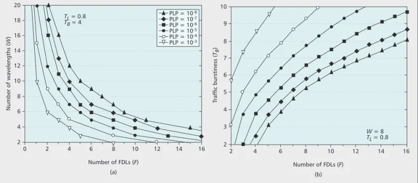
In Fig. 3a we depict the joint requirement of the total number of wavelengths and the number of FDLs for achieving various grades of PLP. For instance, to achieve a PLP of 10–8requires 16 wavelengths and 3 FDLs or 8 wavelengths and 7 FDLs. This result reveals that for this example, to achieve greater scalability with two clusters (an 8 × 8 vs. 16 × 16 switch), the system can achieve the same loss performance by using a marginally greater FDL number (7 vs. 3). Besides, with the same number of wavelengths, applying only a few optical buffers immediately yields drastic improvement in PLP, as indicated by the large slopes when the buffer size is small. This fact justifies the economical use of a down-sized optical buffer in our system. In Fig. 3b, we delineate the number of FDLs that is required for the guarantees of different grades of PLP under various traffic burstiness. We observe that, given any buffer size, the greater the burstiness, the poorer the loss probability. The result pro-vides a guideline on the requirements of the number of FDLs for achieving an acceptable grade of PLP under any given traffic burstiness.
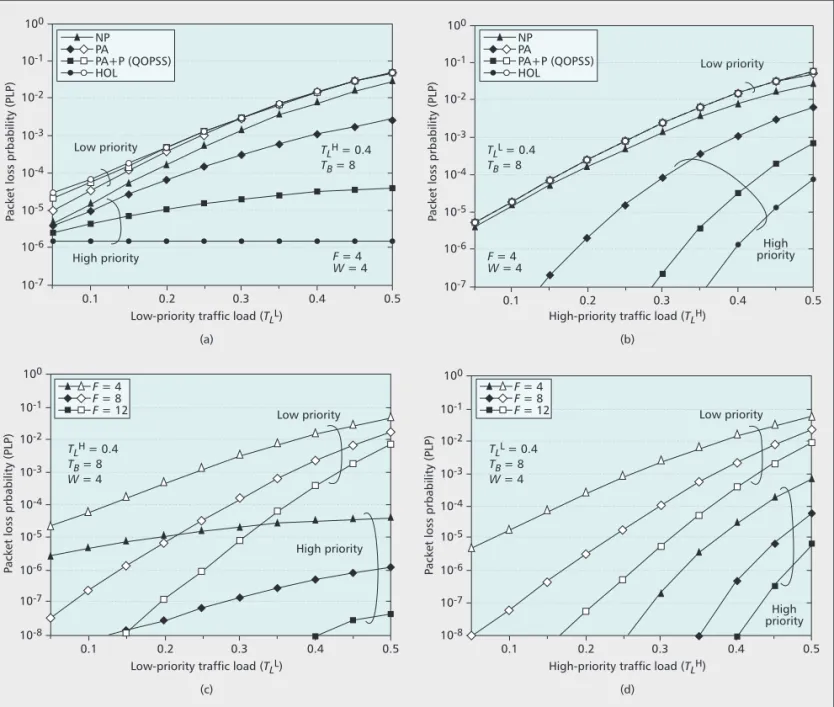
We further demonstrate the provision of QoS differentiation in terms of packet loss perfor-mance. In the simulation, among the 10W con-nections, there are two priorities (H and L) contributing the same amount of traffic load. All other parameter settings are identical to those described above. We draw a comparison of PLP among four following QoS scheduling schemes: • No priority (NP)
• Priority upon arrivals (PA)
• QoS scheduling for QOPSS (i.e., priority upon arrivals with preemption [PA+P]) • Head-of-line priority (HOL)
While the PA scheme provides an entry-level priority where priority takes effect only upon arrival, the HOL scheme is portrayed as an ideal one that gives absolute priority to high-priority packets at all times. Note that the HOL scheme cannot be realized for optical networks with non-circulated FDL-based buffers, and is used solely for comparison purposes. Simulation results are shown in Fig. 4.
In Fig. 4 we display PLP as a function of increased low-priority and high-priority traffic loads in Figs. 4a and 4b, respectively. With the ideal HOL scheme, the loss probability of high-priority packets remains completely unaffected by the increasing low-priority loads. We discover from Fig. 4a that our scheme (PA+P) incurs slightly deteriorating loss probability but outper-forms the PA and NP schemes by several orders of magnitude. When the high-priority traffic load increases (Fig. 4b), all four schemes undergo deteriorating loss probability. Nevertheless, com-pared to the NP and PA schemes, our scheme (PA+P) yields drastic improvement in loss prob-ability due to the preemption feature. In Figs. 4c and 4d we focus on the loss probability of our PA+P scheme under different optical buffer sizes and traffic loads. As shown in the figures, even though our scheme exhibits inferior loss probability compared to the ideal HOL case, such inferiority can be cost-effectively
compen-Figure 3. Packet loss probability (PLP) guarantees under various system and traffic settings: a) wavelength and FDL numbers
require-ments; b) FDL number requirement under various burstiness.
Number of FDLs (F) 0 6 Number of wavelengths ( W ) 4 2 8 10 12 14 16 18 20 2 4 6 8 10 TL = 0.8 TB = 4 W = 8 TL = 0.8 (a) 12 14 16 Number of FDLs (F) 2 4 Traffic burstiness ( TB ) 3 2 5 6 7 8 9 10 4 6 8 10 12 (b) 14 16 PLP = 10-8 PLP = 10-7 PLP = 10-6 PLP = 10-5 PLP = 10-4 PLP = 10-3
sated for by using slightly larger buffers. We observe that, due to the preemption feature, QOPSS achieves superior QoS differentiation by offering high-priority traffic lower loss probabili-ty by several orders of magnitude than that of low-priority traffic.
E
XPERIMENTATION
S
ETUP AND
R
ESULTS
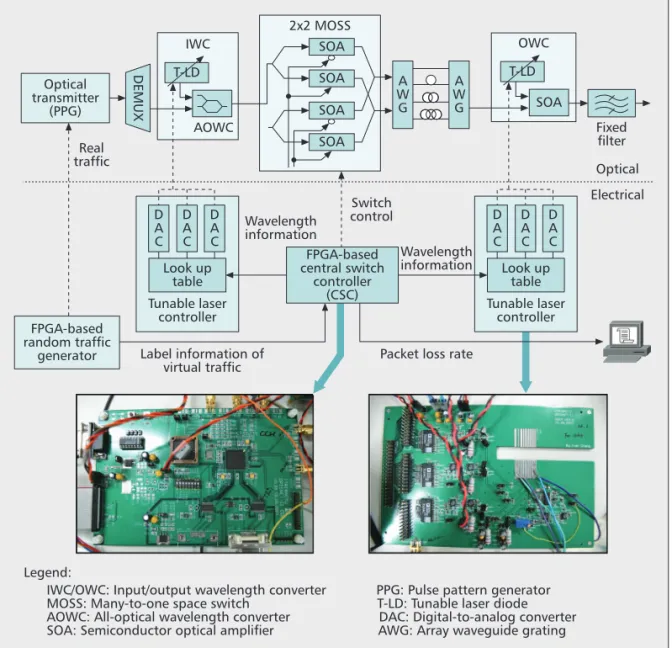
To demonstrate the feasibility and performance of QOPSS, we have implemented an experimen-tal testbed, as shown in Fig. 5. The testbed oper-ates at a data rate of 10 Gb/s and is time-slotted with each slot 2 μs long. Without loss of generali-ty, we only implement one signal path in the optical switch, as shown in the upper part of Fig. 5. In the control plane a field-programmable gate array (FPGA)-based traffic generator produces four traffic channels using two labels and two pri-orities. For each channel, the traffic arrivals are
generated following an IBP described above. The first-channel traffic is used to trigger the 10 Gb/s pulse pattern generator (PPG) to actually pump out packets. The remaining three channels’ infor-mation is passed to the CSC to virtually emulate desired traffic and loads. The FPGA-based CSC reads the label information and schedules pack-ets (by determining the optical data path) accord-ing to the QoS schedulaccord-ing control algorithm (PA+P). The optical data path is uniquely deter-mined by the input and output wavelengths, and a path in the two-by-two MOSS. The CSC then sends the wavelength information to the tunable laser controllers, which contain lookup tables of the currents for controlling the three-section dis-tributed Bragg reflector (DBR) tunable laser diodes in IWC and OWC. The CSC also sends four on/off signals to the SOAs, setting up the path in the MOSS. In the meantime, the CSC updates the mean packet loss rate periodically displayed on a PC.
In the optical data path, the channels of the
Figure 4. Comparisons of different QoS scheduling schemes with respect to packet loss probability: a) four QoS schemes: fixed
high-prior-ity load; b) four QoS schemes: increasing high-priorhigh-prior-ity load; c) PLP of QOPSS: fixed high-priorhigh-prior-ity load; d) PLP of QOPSS: increasing high-priority load.
Low-priority traffic load (TLL)
0.1 10-6
P
acket loss prbability (PLP)
10-7 10-5 10-4 10-3 10-2 10-1 100 0.2 (a) 0.3 Low priority Low priority Low priority Low priority High priority High priority High priority High priority F = 4 W = 4 F = 4W = 4 TLH = 0.4 TB = 8 TLL = 0.4 TB = 8 0.4 0.5
High-priority traffic load (TLH)
0.1 10-6
P
acket loss prbability (PLP)
10-7 10-5 10-4 10-3 10-2 10-1 100 0.2 (b) 0.3 0.4 0.5
Low-priority traffic load (TLL)
0.1 10-6
P
acket loss prbability (PLP)
10-8 10-7 10-5 10-4 10-3 10-2 10-1 100 0.2 (c) 0.3 0.4 0.5
High-priority traffic load (TLH)
0.1 10-6
P
acket loss prbability (PLP)
10-8 10-7 10-5 10-4 10-3 10-2 10-1 100 0.2 (d) 0.3 0.4 0.5 F = 4 F = 8 F = 12 NP PA PA+P (QOPSS) HOL NP PA PA+P (QOPSS) HOL TLL = 0.4 TB = 8 W = 4 F = 4 F = 8 F = 12 TLH = 0.4 TB = 8 W = 4
input fiber port are first demultiplexed and passed to input wavelength converters. The input wavelength used in the experiment is 1550.92 nm. Based on the XPM technique, the input wavelength converter is implemented by a fast DBR tunable laser and Mach-Zehnder interfer-ometer [23]. The signal on the input wavelength (1550.92 nm) is converted to one of four AWG internal wavelengths (1544.13 nm, 1545.72 nm, 1550.52 nm, and 1552.12 nm), which correspond to 0, 1-packet (2 μs), 2-packet (4 μs), and 3-packet (6 μs) delays, respectively, to be received later in the fiber delay lines.
Packets are passed to the MOSS implement-ed by four SOAs that function as on/off gates in addition to four fiber couplers. Provided with a 140 mA switching current to each SOA, the MOSS achieves a switching time less than 50 ns and an on/off extinction ratio greater than 30 dB. Packets then pass through the designated FDL determined by the internal wavelength. The FDLs serve as a shared buffer that incorpo-rates two cyclic AWGs as input and output stages. Multiple packets that depart from the same output port of the AWG are simultaneous-ly converted via the four-wave-mixing (FWM)-based [17] wavelength converter with a
conversion efficiency of 10 dB. The desired out-put wavelength in the experiment is 1540.56 nm. Packets that are outside of this wavelength are preempted and dropped after passing through the fixed optical filter (or multiplexer).
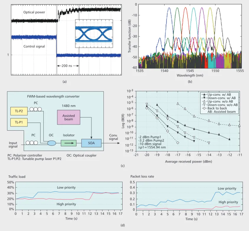
Experimental results are shown in Fig. 6. Recall that the response speed of the XPM-based wavelength converter is determined by the tunable laser’s tuning time, which is less than 200 ns in our case, as shown in Fig. 6a. With the open eye diagram shown in the inset, we demon-strate that the signal integrity is finely main-tained after the converter. For the AWG optical buffer, the average insertion loss of an AWG is 4 dB. As displayed in Fig. 6b, the transmission spectrum of the AWG retains uniform power loss across all wavelengths. Next, we present the functional diagram of the FWM converter in Fig. 6c. The converter generates the FWM phe-nomenon using two tunable pump lasers (TL-P1 and TL-P2) along with the input wavelength, and an additional assisted beam injected into the SOA. As indicated by the bit error rate (BER) curves in Fig. 6c, the use of an additional assist-ed beam yields a significant improvement in the conversion efficiency. For both up and down conversions, the results show that our converter
Figure 5. Experimental setup of the QOPSS testbed.
Legend:
IWC/OWC: Input/output wavelength converter PPG: Pulse pattern generator MOSS: Many-to-one space switch T-LD: Tunable laser diode AOWC: All-optical wavelength converter DAC: Digital-to-analog converter SOA: Semiconductor optical amplifier AWG: Array waveguide grating
Look up table Tunable laser controller Label information of virtual traffic
Packet loss rate D A C Fixed filter Optical Electrical DEMUX Optical transmitter (PPG) Real traffic T-LD SOA 2x2 MOSS A W G A W G AOWC IWC T-LD OWC SOA SOA SOA Switch control Wavelength information Wavelength information SOA FPGA-based random traffic generator FPGA-based central switch controller (CSC) D A C D A C Look up table Tunable laser controller D A C D A C D A C
In the control plan an FPGA-based traffic generator produces four traffic
channels using two labels and two priorities. For each channel, the traffic arrivals are generated following an IBP. The first-channel traffic is used to trigger the
10 Gb/s pulse pattern generator to
actually pump out packets. The remaining three channels’ information is passed to the CSC to virtually emulate desired traffic and
with the assisted beam achieves much lower BER than that without the assisted beam. Final-ly, we depict the mean packet loss rate over time according to a given traffic load scenario in Fig. 6d. In this scenario, the low-priority traffic load is first increased at the third second, followed by an increase of the high-priority traffic load at the 12th second. Testbed results show that low-pri-ority traffic suffers a higher loss rate immediate-ly after the third second. However, high-priority traffic experiences unaffected loss rate until the 12th second. It then inevitably undergoes higher loss rate after the 12th second when the traffic load of the same class has increased. Meanwhile, low-priority traffic suffers worsening packet loss rate as a result of more preemption by high-pri-ority traffic.
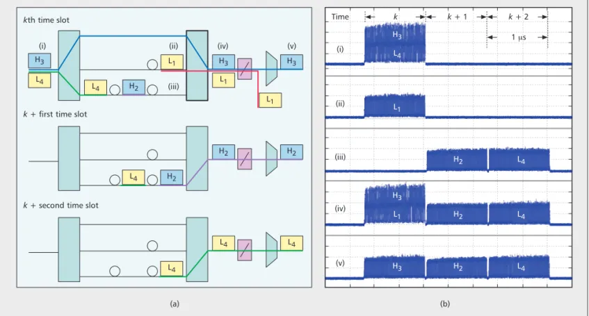
We next demonstrate packet preemption in
Fig. 7 with experimental testbed results. The scenario for the experiment is illustrated in Fig. 7a. For the scenario, Fig. 7b contains the traces that are taken from the digital waveform scope showing the presence of packets at five different stages (i to v) of the system. In the scenario, the system has a buffer size of two in addition to the zero-delay delay line. Prior to the kth time slot, there are two packets in the buffer: low-priority packet 1 (L1) and high-priority packet 2 (H2). At the kth time slot, two new packets (packets H3and L4) arrive at the system. Due to being able to accommodate at most three pack-ets, H3is scheduled to preempt L1, which is going to depart from the system at the next time slot. In addition, packet L4is scheduled to be placed at the end of the buffer. To this end, H3 is set with the internal wavelength so that it can
Figure 6. Experimental testbed results: a) cross-phase-modulation (XPM) converter; b) AWG optical buffer; c) FWM-based wavelength
converter and its performance (conversion range = 25 nm); d) traffic load and resulted mean packet loss rate over time.
PC: Polarizer controller OC: Optical coupler TL-P1/P2: Tunable pump laser P1/P2
Input signal Conv. signal TL-P2 Assisted beam 1480 nm TL-P1 SOA PC PC
FWM-based wavelength converter
OC Isolator (a) Wavelength (nm) (b) (c) (d) 1540 1535 -50 1 -60 Transfer function (dB) -40 -30 -20 -10 0 1545 1550 1555
Average received power (dBm) -20 10-12 Log (BER) 10-13 10-11 10-10 10-9 10-8 10-7 10-6 10-5 10-4 10-3 -21 -19 -18 -17 -16 -15 -14 -13 -12 -11 Time (s) Traffic load 10% 0% 20% 30% 40% 50% 1 0 2 3 4 5 6 7 8 9 10 11 12 13 14 15 16 17 Time (s) Packet loss rate
1 0.1 0 0.2 0.3 0.4 0.5 0 2 3 4 5 6 7 8 9 10 11 12 13 14 15 16 17 Up-conv. w/ AB Down-conv. w/ AB Up-conv. w/o AB Down-conv. w/o AB Back to back AB: Assisted beam 200 ns
Optical power
Control signal
High priority High priority
Low priority Low priority
-2 dBm Pump1 -3.2 dBm Pump2 -10 dBm signal λp1=1554.94 nm
travel through the buffer with no delay. As expected, both packets H3and L1depart from the buffer at the kth time slot simultaneously. This is shown in stage iv in Fig. 7b by the wave-form’s amplitude, which is twice as high as that of a single-packet. The FWM-based wavelength converter is tuned so that H3’s wavelength matches the output wavelength, 1540.56 nm. As a result, packet H3is passed where packet L1is blocked by the multiplexing filter after the con-verter, shown in stage v in Fig. 7b. Finally, pack-et L4exits from the system at the k + 2nd time slot. From the scope traces in Fig. 7b, we observe that QOPSS provides packet buffering and preemption in a fully precise and syn-chronous manner.
C
ONCLUSIONS
In this article we have presented the architec-tural design and experimental testbed demon-stration of QOPSS, a 10 Gb/s QoS optical packet switching testbed system for WDM networks. The architecture of QOPSS includes XPM wave-length converters, MOSSs, AWG-based optical buffers, and FWM wavelength converters for the optical switching, buffering, and preemption of packets. We show simulation results to empha-size that to achieve higher system scalability with more space-switch clusters, QOPSS can guaran-tee the same grade of PLP by using a marginally larger buffer size, revealing the economic use of a handful of optical buffers. As a result of the preemption feature, QOPSS was shown to achieve superior QoS differentiation by offering high-priority traffic lower loss probability by sev-eral orders of magnitude than that of low-priori-ty traffic. Experimental results demonstrated that the system components achieve high signal
integrity, uniform signal power, and low bit error rate, justifying the feasibility of the system. Finally, we observe from the waveform scope that, for a given scenario, the QOPSS testbed system precisely and synchronously performed the switching, buffering, and preemption of packets.
R
EFERENCES[1] M. Yuang et al., “HOPSMAN: An Experimental Testbed System for a 10 Gb/s Optical Packet-Switched WDM Metro Ring Network,” IEEE Commun. Mag., vol. 46, no. 7, July 2008, pp. 158–66.
[2] M. Yuang et al., “Optical Coarse Packet-Switched IP-over-WDM Network (OPSINET): Technologies and Experiments,”
IEEE JSAC, vol. 24, no. 8, Aug. 2006, pp. 117–27.
[3] G. Papadimitriou, C. Papazoglou, and A. Pomportsis, “Optical Switching: Switch Fabrics, Techniques, and Architectures,” J. Lightwave Tech., vol. 21, no. 2, Feb. 2003, pp. 384–405.
[4] S. Li, Algebraic Switching Theory and Broadband
Appli-cations, Academic Press, 2001.
[5] A. Jajszczyk, “Nonblocking, Repackable, and Rear-rangable Clos Networks: Fifty Years of the Theory Evo-lution,” IEEE Commun. Mag., vol. 41, no. 10, Oct. 2003, pp. 28–33.
[6] G. Chang et al., “Enabling Technologies for Next-Gener-ation Optical Packet-Switching Networks,” Proc. IEEE, vol. 94, no. 5, May 2006, pp. 892–910.
[7] R. Tucker, P. Ku, and C. Hasnain, “Slow-Light Optical Buffers: Capabilities and Fundamental Limitations,” J.
Lightwave Tech., vol. 23, no. 12, Sept. 2005, pp.
4046–66.
[8] S. Dixit, IP over WDM: Building the Next Generation
Optical Internet, Wiley, 2004.
[9] M. Chia et al., “Packet Loss and Delay Performance of Feedback and Feed-Forward Arrayed-Waveguide Grat-ings-Based Optical Packet Switches With WDM Inputs-Outputs,” J. Lightwave Tech., vol. 19, no. 9, Sept. 2001, pp. 1241–54.
[10] Z. Zhang and Y. Yang, “Low-Loss Switching Fabric Design for Recirculating Buffer in WDM Optical Packet Switching Networks Using Arrayed Waveguide Grating Routers,” IEEE Trans. Commun., vol. 54, no. 8, Aug. 2006, pp. 1469–72.
Figure 7. Demonstration of packet preemption: a) the scenario; b) traces displayed in optical scope.
(i) (ii) (iii) (iv) (v) H3 L1 H3 H3 L1 L1 L4 L4 H2 kthtime slot
k + firsttime slot
(b) (a) (v) (iv) (iii) (ii) (i) Time k k + 1 k + 2 1 μs H2 H2 L4 H2
k + secondtime slot
L4 L4 L4 H3 H2 L4 H3 L1 H2 L1 H3 L4 L4 H2 L4
[11] S. Liew, G. Hu, and H. Chao, “Scheduling Algorithms for Shared Fiber-Delay-Line Optical Packet Switches — Part I: The Single-State Case,” J. Lightwave Tech., vol. 23, no. 4, Apr. 2005, pp. 1586–1600.
[12] F. Choa et al., “An Optical Packet Switch Based on WDM Technologies,” J. Lightwave Tech., vol. 23, no. 3, Mar. 2005, pp. 994–1014.
[13] T. Zhang, K. Lu, and J. Jue, “Shared Fiber Delay Line Buffers in Asynchronous Optical Packet Switches,” IEEE
JSAC, vol. 24, no. 4, Apr. 2006, pp. 118-127.
[14] V. Eramo, M. Listanti, and M. Spaziani, “Resources Sharing in Optical Packet Switches with Limited-Range Wavelength Converters,” J. Lightwave Tech., vol. 23, no. 2, Feb. 2005, pp. 671–87.
[15] V. Eramo, M. Listanti, and A. Germoni, “Cost Evalua-tion of Optical Packet Switches Equipped With Limited-Range and Full-Limited-Range Converters for Contention Resolution,” J. Lightwave Tech., vol. 26, no. 4, Feb. 2008, pp. 390–407.
[16] B. Sarker, T. Yoshino, and S. Majumder, “All-Optical Wavelength Conversion Based on Cross-Phase Modula-tion (XPM) in a Single-Mode Fiber and a Mach-Zehnder Interferometer,” IEEE Photonics Tech. Letters, vol. 14, no. 3, Mar. 2002, pp. 340–42.
[17] D. Hsu et al., “High-Efficiency Wide-Band SOA-based Wavelength Converters by using Dual-Pumped Four-Wave Mixing and an Assist Beam,” IEEE Photonics Tech.
Letters, vol. 16, Aug. 2004, pp. 1903–5.
[18] J. P. Mack, H. N. Poulsen, and D. J. Blumenthal, “Vari-able Length Optical Packet Synchronizer,” IEEE
Photon-ics Tech. Letters, vol. 20, July 2008, pp. 1252–54.
[19] W. Feng and W. D. Zhong, “Noise Analysis of Photon-ics Packet Synchronizer,” J. Lightwave Tech., vol. 22, Feb. 2004, pp. 343–50.
[20] Y. Lin et al., “Using Superimposed ASK Label in a 10 Gb/s Multihop All-Optical Label Swapping System,” J.
Lightwave Tech., vol. 22, no. 2, Feb. 2004, pp. 351–61.
[21] M. Yuang, P. Tien, and S. Lin, “A Pseudo-Banyan Opti-cal WDM Packet Switching System with Near-Optimal Packet Scheduling,” IEEE/OSA J. Optical Commun. Net., vol. 1, no. 3, Aug. 2009, pp. B1–B14.
[22] M. Yuang et al., “QoS Scheduler/Shaper for Optical Coarse Packet Switching IP-over-WDM Networks,” IEEE
JSAC, vol. 22, no. 9, Nov. 2004, pp. 1766–80.
[23] J. Leuthold et al., “All-Optical Mach-Zehnder Interfer-ometer Wavelength Converters and Switches with Inte-grated Data- and Control-Signal Separation Scheme,” J.
Lightwave Tech., vol. 17, June 1999, pp. 1056–66.
B
IOGRAPHIESMARIAC. YUANG[SM] ([email protected]) received her Ph.D. degree in electrical engineering and computer science from Polytechnic University, Brooklyn, New York, in 1989. From 1981 to 1990 she was with AT&T Bell Labora-tories and Bell Communications Research (Bellcore), where she was a member of technical staff working on Broad-band networks and protocol engineering. In 1990 she joined National Chiao Tung University (NCTU), Taiwan, where she is currently a professor of the Department of Computer Science. She has served as a Guest Editor for
IEEE Journal on Selected Areas in Communications (Special
Issue on Next-Generation Broadband Optical Access Net-work Technologies) in 2009. She has served on the techni-cal program committees of many technitechni-cal conferences
including IEEE ICC and GLOBECOM, and has been invited to give talks at many technical conferences. Her main research interests include broadband optical networks, wireless networks, multimedia communications, and per-formance modeling and analysis. She is a member of OSA. She holds 17 patents in the field of broadband networking and has over 100 publications, including a book chapter. YU-MINLIN[M] ([email protected]) received his B.S. degree in electrical engineering from National Tsing-Hua University, Taiwan, in 1996 and his Ph.D. degree in com-munication engineering from NCTU in 2003. He joined the Department of Optical Communications and Networks, Industrial Technology Research Institute (ITRI), Taiwan, in 2004. His research interests include broadband optical net-working and optical packet switching.
JU-LINSHIH[M] ([email protected]) received his Ph.D. degree in computer science and information engineering from NCTU in 2006. He joined NCTUniversity in 2006, where he is currently a postdoctoral fellow in the Depart-ment of Computer Science. His current research interests include high-speed networking, optical networking, wire-less local networking, and performance modeling and anal-ysis.
PO-LUNGTIEN[M] ([email protected]) received his B.S. degree in applied mathematics, M.S. degree in computer and information science, and Ph.D. degree in computer sci-ence and information engineering from NCTU in 1992, 1995, and 2000, respectively. In 2005 he joined NCTU, where he is currently an assistant professor in the Depart-ment of Electrical Engineering. His current research inter-ests include optical networking, computational intelligence, network optimization, multimedia communications, and performance modeling.
JA S O N(JY E H O N G) CH E N[M] ([email protected]) received his Ph.D. degree in electrical engineering and computer science from the University of Maryland, Balti-more, in 1998. He joined JDSU in 1998 as a senior engi-neer and obtained 10 U.S. patents in two years. He joined the faculty of NCTU in 2003, where he is currently an asso-ciate professor in the Institute of Electro-Optical Engineer-ing and Department of Photonics.
STEVENS. W. LEE[M] ([email protected]) received
his Ph.D. degree in electrical engineering from National Chung Cheng University, Taiwan, in 1999. He joined the Industrial Technology Research Institute (ITRI), Taiwan, in fall 1999, where he was a project leader on optical net-working. In 2008 he joined the faculty of National Chung Cheng University, where he is currently an associate profes-sor ub the Department of Communications Engineering. His research interests include optical networks, network planning, and network optimization.
SHIH-HSUANLIN([email protected]) received his B.S. degree from the Department of Computer Science, Nation-al Tsing Hua University, Taiwan, in 2002, and his M.S. degree from the Department of Computer Science, NCTU, in 2004. He is currently working toward his Ph.D. degree in the same department. His research interests include optical networks, wireless data networks, performance modeling and analysis, and optimization theory.
We show simulation results to emphasize that, to achieve higher system scalability with more space-switch clusters, QOPSS can guarantee the same
grade of PLP by using a marginally
larger buffer size, revealing the economic use of a
handful of optical buffers.