1532-5008/ 02 $12.00 + .00 DO I: 10.1080/ 15325000290085136
A Novel Design of Optimal Phase Current
Waveform for an Electric Vehicle Wheel Motor
YEE-PIEN YANG
YIH-PING LUH
CHI-MING LEE
Department of Mechanical Engineering National Taiwan University
No. 1, Roosevelt Road, Sec. 4 Taipei, Taiwan 106, R.O.C.
A novel design of optimal current waveform for a disc-type axial-ux wheel mo-tor is presented in this paper. This dedicated wheel momo-tor has been designed and installed directly inside the wheel of electric vehicles without mechanical diŒer-entials and reduction gears. The torque-oriented optimization is performed to obtain the optimal current waveform subject to various constraints for indepen-dent winding structure. The best one of the optimal waveforms for maximized torque with conned ohmic loss is found to be proportional to the magnetic ux variation in the air-gap between the stator and the rotor.
Keywords axial-ux wheel motor, optimal driving waveform, electric vehicle
1. Introduction
Electric vehicles (EVs) have played an important role in the protection of natural environment. Traditional power systems of EVs consist of batteries, electric motors with drives, and transmission gears to wheels. Each subsystem converts chemical, electrical, or mechanical energy into diŒerent forms, thus consuming energy through the dissipation components of windage and friction. Researchers and engineers are looking for various approaches to improve the overall e ciency of electric vehicles, and hence to increase their driving range. In addition to new battery technologies, new concepts for the design of motor and their optimal driving pattern have at-tracted substantial attention for the improvement of overall e ciency and reliability of EVs.
One of the new motor designs used in this paper is the wheel or hub-in motor directly mounted inside the wheel, thus eliminating transmission gears or mechan-ical diŒerentials with their associated energy loss. In addition, the reduction of mechanical components in transmission chains or gears not only improves
over-Manuscript received in nal form on 30 July 2001.
The authors acknowledge the nancial support of the National Science Council of Taiwan, Republic of China, under Contract No. NSC88-2622-E-002-003.
Address correspondence to Prof. Yee-Pien Yang. E-mail: [email protected]
all e ciency but also reduces vehicle weight. Various axial-ux wheel motors have been proposed for electric cars [1{4]. Lacking reduction gears, mechanical transmis-sion, and diŒerential, most wheel motors need large input current to develop large torque at low speed operation; however, greater ohmic loss, which is proportional to the square of current, caused inevitable reduction of e ciency. Therefore, a proper driving current pattern is one of critical solutions in increasing the EV’s e ciency. Optimal control waveforms have attracted considerable attention from research-ers and engineresearch-ers for a variety of electric motors. In order to produce maximum torque per stator current at various operating conditions, Ohm [5] developed an algorithm to nd the optimal advance angle of the desired stator current command for PM synchronous motors. Verl and Bodson [6] discussed torque maximization for PM synchronous motors in the presence of voltage and current constraints through-out the low-, intermediate-, and high-speed regions. Low et al. [7] proposed a motor identity modeling approach to determine the optimal current prole to maximize torque for driving the permanent magnet synchronous motor. A system of two-loss model controllers was proposed by Mademlis et al. [8] to determine the optimal air-gap ux and the optimal excitation current to minimize losses; however, most optimal current waveforms were based on the conventional assumption of motors that their back emf was square, trapezoidal, or sinusoidal due to the lack of de-sign information on the shape of the magnetic eld ux distribution in the air gap between the rotor and the stator.
This paper presents a novel approach for determining the optimal current pat-tern for the disc-type axial-ux brushless DC wheel motor by maximizing the output torque with respect to the rotor shift. In terms of original design parameters, the magnetic circuit model of the customized motor is established. The air gap charac-teristics, such as torque, ux, and its variation, are described as functions of rotor shift. The eld ux variation, and hence the back emf, is not anymore a regular function of sine, square, or trapezoid. The resulting optimal current waveform is proved by Cauchy-Schwarz inequality and is veried numerically through optimiza-tion schemes with various constraints. Finally, the plan of implementaoptimiza-tion proposes a novel sensor structure for current switching and for precise tracking of the optimal current pattern stored in a digital signal processor.
2. Axial-Flux Wheel Motor
2.1. Specication
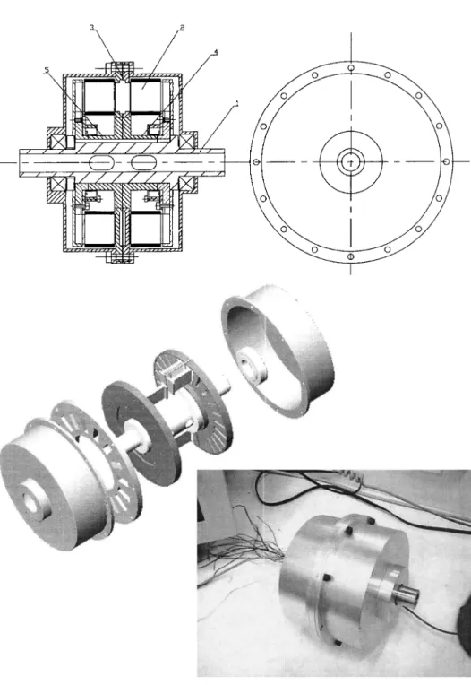
The dedicated disc-type axial-ux brushless DC wheel motor presented in this paper is a prototype for electric vehicles, as developed in the Electro-mechanical Power System Research Group at National Taiwan University. The cross-sectional view, explosive graph, and prototype of the wheel motor are illustrated in Figure 1, and its primary components and specications are listed in Table 1. Figure 1 shows diagrammatically a non-salient-pole rotor disc of the hub-in motor with 16 magnets of two at surfaces to form 16 poles, and it is sandwiched between two plates of stator, each with 24 teeth. This indicates that the slot pitch of two adjacent slots is 2/3 pole pitch, and the number of slots per pole per phase is 1/2. This fractional pitch arrangement yields a uniform magnetic force distribution between the stator and the rotor, hence eliminating most of the cogging torque that usually occurs in permanent-magnet motors. The ND27SH NbFeB magnet is used, which has
Figure 1. The cross-sectional view, explosive graph, and prototype of axial-ux disc-type
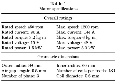
Table 1 Motor specications
Overall ratings
Rated speed: 450 rpm Max. speed: 1200 rpm Rated current: 96 A Max. current: 144 A Rated torque: 3.2 kg-m Max. torque: 6 kg-m Rated voltage: 15 V Max. voltage: 48 V Rated power: 1.5 kW Max. power: 3.0 kW
Geometric dimensions
Outer radius: 89 mm Inner radius: 60 mm
Air gap length: 0.5 mm Number of coils per tooth: 130 Number of phase: 3 Coil diameter: 0.6 mm
remanence of 1.05 Tesla and coercivity of 9.5 kOe. The laminated electric steel sheets 35RM230 (0.35 mm) have core loss of 2.2 W/kg at 1 Tesla and 100 Hz, and their saturation ux density is between 1.4 and 1.9 Tesla. The tire is installed on the outer case rotating with the rotor. The main magnetic ux ows through two air-gaps between the stator and rotor along the axial direction.
The nal shape of this wheel motor is designed to meet required specications of a multifunctional optimization scheme, with various constraints, such as limited space, current density of conductor, ux saturation, and driving voltage. Instead of being Y-connected, the coils are independently wired on stator poles and are grouped into three phases. Independent winding structure is one of the features of this dedicated wheel motor, in which the stator coils are independently wound and bound into required phases. Since there is no neutral point for independent winding, the driving voltage is directly applied to each phase. Therefore, larger back electromotive force is induced and higher motor speed can be reached.
2.2. M agnetic Circuit M odel
The torque of electric motors is produced by the rate of change of the magnetic energy stored in the air-gap. The magnetic energy comes out from the magnetic eld created by the current owing in the wires and/or permanent magnets. Both sources generate magnetic ux forming ux loops in the magnetic materials of the motor. Based on the assumptions of material linearity and the collinearity of ux and eld densities, the magnetic circuit model is used to describe the torque produced in the motor. It is also necessary to make three additional assumptions:
(1) The motor is operated in the linear range of the B-H curve of magnetic materials.
(2) The air-gap reluctance of the slotted stator structure is approximated by eŒective air-gap length with Carter’s coe cient [9].
(3) The ux ows straight across the air-gaps between the stator and rotor, namely, the overlapping area method, ignoring the fringing ux for simpli-ed analysis.
The eld coenergy within the air-gap of the axial-ux wheel motor is expressed in the form W0(³ ) = 1 2 X i=a , b,c [(Rg i+ RP)¿ 2P i+ LiIi2+ 2N ¿ P iIi]; (1)
where N is the number of turns per tooth, Rg iis the air-gap reluctance
correspond-ing to the coil windcorrespond-ing phase i, RP is the magnet reluctance, ¿ P i is the magnet
ux owing through coil winding phase i, and Li and Ii are the self-inductance
and exciting current of coil winding phase i, respectively. It is apparent that Rg i,
¿ P i, and Li are functions of rotor shift (i.e., the relative angular position of rotor
and stator) but RP is not. The total torque consisting of cogging, reluctance, and
alignment torques is obtained from the rate of change of the eld coenergy in a linear operation range as follows:
T = @W 0(³ ) @³ = 1 2 X i=a , b,c · ¡ dRg i d³ ¿ 2 P i¡ dRi d³ ¿ 2 C i+ 2N Ii d¿ P i d³ ¸ ; (2)
where ¿ C i is the ux produced by coil i owing through the air-gap and rotor
magnets and Riis composed of air-gap and rotor magnet reluctances through which
¿ C i ows. The second term is the other expression of the reluctance torque due to
the fact LiIi2= Ri¿ 2C i [10].
In the above expression, the rst term is the cogging torque produced by the rotor magnets, which is the rate of change of the stored magnetic energy in the air-gap between stator teeth and rotor poles. As this portion of torque is evaluated, the stator coils are not excited by phase currents but linked with the ux owing out of rotor magnets. The second term represents the reluctance torque occurring whenever the air-gap reluctance is decreasing and the inductance associated with coils is increasing. Regardless of the ux from magnets, this torque component is calculated only with the ux produced by coils, and its peak ratio is less than 0.5% of the gross torque of the dedicated wheel motor. The third term in (2), called mutual or alignment torque, happens as the mutual ux links the magnet to the coil. This is the primary torque component of a brushless DC motor.
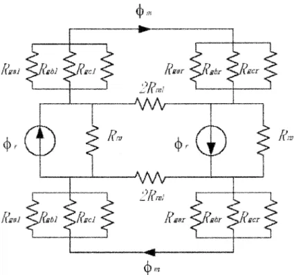
The 3D motor structure can be simplied to a 2D conguration, as shown in Figure 2, for facilitating the magnetic circuit analysis. The laminations of the stator are composed of sheets of electric steel and are oriented in a stack coming out of the paper. In a section of 360 electrical degrees, the magnetic circuit of one ux loop is composed of three teeth on each side of the stator facing toward two permanent magnets embedded in the rotor. As a matter of fact, the ferromagnetic material has very high permeability and its reluctance can be ignored. Figure 3 shows that the magnet ux splits into the stator teeth from one side and returns from the other side, the air gap reluctance facing each stator tooth varies with the rotor shift [10]. For example, Rg a l is a variable air gap reluctance corresponding to left branch of
the ux splitting into phase a, and similar denitions are used for Rg bl and Rg cl.
Moreover, 2Rm l denotes the ux leakage reluctance from magnet to magnet, and ¿ r
denotes the ux source of a magnet with reluctance Rm. Through basic electrical
and mechanical relationships, the air gap ux corresponding to phase i along the left branch of the circuit is expressed as
¿ P il(³ ) =
1=Rg a l
1=Rg a l+ 1=Rg bl + 1=Rg c l
Figure 2. Two-dimensional motor structure in 2º electric angle (L L¢).
Figure 4. Air gap ux in three phases.
where ¿ P il is a function of the rotor shift ³ and ¿ m is the magnet ux leaving the
magnet and crossing the air gap. Similar expressions hold for the right branch of the circuit. In that way, the summation of uxes corresponding to three phases at any rotor shift is equivalent to the total air gap ux in one magnetic loop. Subscript omission for left and right branch yields
¿ P a + ¿ P b+ ¿ P c = ¿ m: (4)
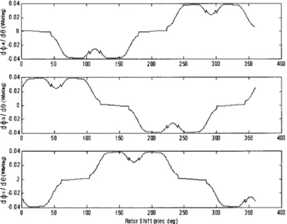
In other words, at any rotor shift, the magnet ux crossing the air gap nds its way getting into three phase coils and completes a loop. Figure 4 shows the magnetic ux distributions that vary periodically in the air gap between the stator and rotor, and the air gap ux variations in three phases are depicted in Figure 5.
3. Optimal Current Waveform
Since the cogging torque, which is inherent from the original design of the motor, is independent of driving currents, and the reluctance torque is small enough to be neglected, the optimal current waveform is then determined by maximizing the alignment torque in the sense of average. The statement of optimization is described as follows:
The average torque is maximized under a constraint on the average ohmic loss. Hence, the performance index can be expressed as
TA ,a v g =
1 2º
Z 2¼
Figure 5. Air gap ux variations in three phases.
subject to the constraint
Z 2¼ 0 I 2 id³ µ Z 2¼ 0 6 2d³ ; i = a; b; c; (6) where TA(³ ) = 1 2 X i=a , b,c NIi(³ )d¿ P i (³ ) d³ : (7)
Both theoretical and numerical analyses are made for the optimal current wave-form with the following assumptions. First, the motor is operated under the rated speed so that the back-emf induced in each phase of the motor must not exceed the driving voltage. Second, the limitation of current and power loss of the conductor is released, which was prescribed by the maximum allowable current density of the conductor due to its cross section.
3.1. Theoretical Analysis
Theoretically, the optimal current waveform is analyzed by maximizing the torque in the sense of average. In equations (5) and (7), the alignment torque TA, the
magnet ux ¿ P i, and the current input Ii owing through coil winding phase i are
all functions of rotor shift ³ . The average torque TA over an electric period can be
calculated approximately in a summation of n points and expressed as TA ,a v g = 1 2 X i=a , b,c N 2 41 n n X j=1 Ii(j) d¿ P i(j) d³ 3 5 : (8)
From the Cauchy-Schwarz inequality [11] for sums 0 @ 1 X j=1 jajbjj 1 A 2 µ Ã1 X k=1 a2k ! Ã 1 X m=1 b2m ! ; (9)
the maximum value of the left-hand-side summation occurs when the following relationship exists: a1 b1 = a2 b2 = a3 b3 = = c; (10)
in which c is a nonzero constant. Likewise, the maximum average torque takes place when Ii(j) and dÁP idµ(j) are proportional.
This result reveals the following fact:
The maximum torque for the brushless DC motor is obtained by the cur-rent input with the same waveform as the ° ux variation in the air-gap between the stator and the rotor. In other words, the phase of the stator current to produce a maximum torque must have 90 electrical degrees from the permanent magnet ° ux angle of the rotor. In terms of the rotating d-q axis ¯xed on the rotor [12], the control vector has no component in the direct axis, along which the ° ux is purely supplied from the permanent magnet [5].
3.2. Numerical Analysis
In this stage, we will not only verify numerically the optimal current waveform through numerical optimization analysis, but also compare the motor performance with rectangular currents usually applied for brushless DC motors with trapezoidal back emf. The optimizer \constr" in MATLAB is used for maximizing either the average torque (5) over an electric period, or the torque (7) at each point in terms of rotor shift. The design variable is current, which is optimized, point by point at discrete rotor shifts, or is expressed as a current function and optimized iteratively over an electrical period.
In the following optimization process, the constraint on the maximum terminal voltage per phase is given as
!e
d¶ i
d³ + RP H iIi< 48V; i = a; b; c; (11) where !e is the voltage wave speed and ¶ i is the ux linkage to the phase winding
resistance RP H i. This relation illustrates that the back-emf induced in the motor
must not exceed the driving voltage, 48 V; however, for the operation under the rated speed as assumed in the proceeding analysis, this constraint is trivial.
The sequential quadratic programming optimization method in MATLAB is applied to search for the optimal current pattern for each phase. The optimizer as-sembles the penalty and constraint functions with Lagrange multipliers and searches the stationary point of the Lagrangian function by Newton’s method. Thus, it is referred to as the Lagrange-Newton method. This method requires initial estimates for Lagrange multipliers and design variables Ia, Ib, and Ic. Their optimization
Case I: The maximum torque for each relative position of rotor and stator
is produced under the constraint of current limit. In another way, the maximum torque is calculated point by point at each rotor shift where the discrete current is the design variable. Therefore, the performance index is a function of rotor shift ³ and is expressed as (7) subject to the constraint
jIa; Ib; Icj < Imaxamp; (12)
where Imax is limited at 6 amperes by the cross-section of conductor. This yields an optimal current of rectangular waveform with optimal switching angles.
Case II: The average torque is maximized under a constraint on the average
ohmic loss. In this case, the design variable is the current function of rotor shift over an electrical period. Hence, the performance index is expressed as (5) subject to the constraint Z 2¼ 0 I 2 id³ µ Z 2¼ 0 I 2 maxd³ ; i = a; b; c: (13)
This constrains the ohmic loss during an electric period with no limit on the peak current, and thus resulting in a nonrectangular current waveform.
Case I results in an optimal current of rectangular waveform with optimal switching angles at specic rotor shifts, as depicted in Figure 6, in which all the phase currents reach to their limit of 6 amperes as the six-step driving current. The optimal current waveform in Case II, as the theoretical analysis proved, is indeed proportional to the ux variation in the air gap as shown in Figures 5 and 7, in which the peak current is 8.5 amperes. Moreover, its average torque of 7.8 kg-m is larger than that of 6.5 kg-m produced by the optimal current of rectangular waveform, as illustrated in Figure 8. Although their torque ripples are not trivial, they usually are ltered through mechanical inertia.
Figure 7. Optimal current with ohm loss constraint.
Figure 8. Torque produced by (a) optimal rectangular current pattern (solid curve) and
Since both the peak current and load torque are diŒerent in the above results, a similar basis is necessary for the comparison of motor performances. Two reference bases are then made with an average torque of 5 kg-m and a peak current of 6 amperes. Table 2 depicts various performances for the motor operated at a low speed operation of 100 rpm. In these cases, the motor e ciency is calculated by
² = TA ,a v g!
TA ,a v g! + PC + PI + PS
100%; (14)
where ! is the rotor speed, PC is the copper of ohmic loss, and PI is the iron
loss. The stray loss PS comprises windage, friction, noise, and other less dominant
loss components. These losses are functions of phase current waveforms and are determined approximately by PC = X k=a , b,c 1 2º Z 2¼ 0 I 2 k(³ )Rkd³ ; (15)
where Rk is the phase resistance
PI = » V Kf®BM a x¯ ; (16)
where » and V are mass density and volume of the stator steel, respectively, f is the dominant frequency of the input current, and BM a x is the maximum ux density
of the electric steel 35RM230, whose material coe cients are given by K = 0:0079, ¬ = 1:2704, and = 1:7008. The stray loss PS usually is estimated by the designer
and is chosen at 5% of the average output power TA ,a v g! in this paper.
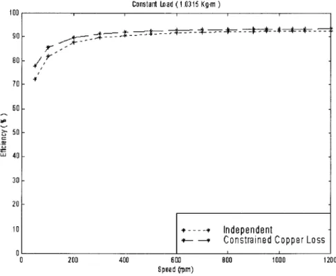
As the result indicates, the e ciencies for Case II with constrained ohmic loss are superior to those for Case I. For the same limit on the peak current, the optimal rectangular current waveform of Case I produces the highest average torque; how-ever, its torque constant is the smallest. In this case, larger torque may be necessary for starting or accelerating operation at lower speed while sacricing some motor e ciency. For high-speed cruising stage of the electric vehicle, the optimal current waveform proportional to the ux variation becomes a better solution for e ciency, which is shown in Figures 9 to 11 for various load torques.
Table 2
Motor performance by optimal current inputs (100 rpm)
Average torque Peak current
Basis load at 5 kg-m limit at 6 amperes
Case I II I II
Max./Avg. torque (kg-m) 5.7/5.0 6.6/5.0 7.3/6.5 7.3/5.5
Torque ripple (%) 13.8 31.9 13.8 31.9
Torque constant (kg-m/A) 0.023 0.029 0.023 0.029
Max. current per pole (A) 4.7 5.4 6.0 6.0
Ohmic loss (Watt) 408 288 679 700
Iron loss (Watt) 15.9 8.7 24.7 18.6
Stray loss (5%) (Watt) 25.7 25.7 33.1 28.3
Figure 9. Motor e ciency vs speed under load of 6.2 kg-m.
Figure 11. Motor e ciency vs speed under load of 1.0 kg-m.
4. Plan Implementation
To realize the optimal driving current waveform, a motor drive must be designed and implemented. It is not di cult to implement the optimal current of rectangu-lar waveform with specic switching angles; however, it is hard to synthesize, by analogy circuit, the nonrectangular optimal waveform that is proportional to the ux variation. A digital signal processor TMS320F2401 is then selected to store the optimal current pattern, to process signals, and to create control outputs. The input signals to the processor include a motor acceleration command, rotor shift position signal, and phase current feedbacks. The rotor shift position is sensed by a reective optosensor, receiving the reecting light from the black-and-white code belt adhered to the inner side of the rotor. Two kinds of rotor shift posi-tions are critically sensed. One informs the switching point for positive current or negative current and the other one relates the position with the magnitude of the current waveform. Two belts of code are then designed and printed on the transparent plastic paper as shown in Figure 12, where two sets of reective opto-sensors, each with three components corresponding to three phases, are located on the stator. One belt consists of eight sets of black-and-white codes. As one of the optosensors receives the forward end of a black belt, the direction of current is changed. The other belt is composed with 720 black-and-white codes so that more precise rotor shifts are sensed and their corresponding current magnitudes
Figure 12. Positioning sensor.
are searched from the digital signal processor, where the optimal current pattern is stored.
The optimal control signals are then generated and converted to pulse-width modulation (PWM) waveforms to the power circuit that sends current pulses through each motor winding. A popular three-phase full bridge circuit is used to accomplish this by implementing 12 power electronic switches (MOSFETs), as shown in Figure 13. A buck converter is built in front of the bridge circuit for adjusting the amplitude of the PWM wave. Then, the power electronics in the three-phase bridge are responsible only for a few hundred hertz of on-oŒswitch-ing action accordon-oŒswitch-ing to the feedback position signal of the rotor. In this paper, the overall e ciency is increased not only by the optimal phase currents but also by the use of a buck converter, which usually is operated in 5 kHz. Without it, the power electronic components must perform high-frequency (about 20 kHz) switching operations, yielding high switching loss. Additional circuits are also in-stalled, protecting the drive from overload; over-current, over-voltage, over-current, or over-voltage transients; high temperature, etc.
5. Summary and Conclusions
The optimal driving current waveform for a disc-type axial-ux brushless DC wheel motor has been successfully designed. The maximum torque with conned ohmic loss is obtained by driving the motor with the optimal current waveform that is proportional to the magnetic ux variation in the air-gap between the stator and the rotor, which is also proved by the Cauchy-Schwarz inequality. A properly selected
Figure 13. Motor drive for independent winding.
digital signal processor will facilitate the realization of the resulting optimal current and is suggested for further validation through experiments. It is worth mentioning that the procedure of obtaining an optimal current waveform must be applied for most DC brushless motors whose major part of torque stems from the alignment torque due to the mutual ux linking the magnet to the coil.
References
[1] F. Profumo, Z. Zhang, and A. Tenconi, 1997, “ Axial Flux Machines Drives: A New Vi-able Solution for Electric Cars,” IEEE Transactions on Industrial Electronics, Vol. 44, No. 1, pp. 39–45.
[2] F. Caricchi, F. Crescimbibi, O. Honorati, A. Di Napoli, and E. Santini, 1996, “ Com-pact Wheel Drive for Evs,” IEEE Industry Applications Magazine, Vol. 2, No. 6, pp. 25–32.
[3] H. C. Lovatt, V. S. Ramsden, and B. C. Mecrow, 1998, “ Design of an In-Wheel Motor for a Solar-Powered Electric Vehicles,” IEE Proceedings: Electric Power Applications, Vol. 145, No. 5, pp. 402–408.
[4] B. Hredzak, S. Gair, and P. Eastham, 1996, “ Elimination of Torque Pulsations in a Direct Drive EV Wheel Motor,” IEEE Transactions on Magnetics, Vol. 32, No. 5, Part 2, pp. 5010–5012.
[5] D. Y. Ohm, 1996, “ Optimized Control Method Produces Maximum Torque in PM Synchronous Motors,” Powerconversion & Intelligent Motion, Vol. 22, No. 8, pp. 30–45.
[6] A. Verl and M. Bodson, 1998, “ Torque Maximization for Permanent Magnet Syn-chronous Motors,” IEEE Transactions on Control System Technology, Vol. 6, pp. 740– 745.
[7] T.-S. Low, C. Bi, and K.-T. Chang, 1996, “ Motor Identity—A Motor Model for Torque Analysis and Control,” IEEE Transactions on Industrial Electronics, Vol. 43, No. 2, pp. 285–291.
[8] C. Mademlis, J. Xypteras, and N. Margaris, 1998, “ Loss Minimization in Wound-Field Cylindrical Rotor Synchronous Motor Drives,” IEEE Transactions on Power
Electronics, Vol. 13, No. 2, pp. 288–296.
[9] V. Ostovic, 1994, Computer-Aided Analysis of Electric Machines, Prentice Hall, New York.
[10] D. C. Hanselman, 1994, Brushless Permanent-Magnet Motor Design, McGraw-Hill, Inc., New York.
[11] E. Kreyszig, 1978, Introductory Functional Analysis with Applications, John Wiley & Sons, New York.
[12] G. R. Slemon, 1992, Electric Machines and Drives, Addison-Wesley Publishing Company, Inc.