Simplified fractional Fourier transforms
Soo-Chang Pei and Jian-Jiun DingDepartment of Electrical Engineering, National Taiwan University, Taipei, Taiwan Received February 25, 2000; revised manuscript received May 31, 2000; accepted August 1, 2000 The fractional Fourier transform (FRFT) has been used for many years, and it is useful in many applications. Most applications of the FRFT are based on the design of fractional filters (such as removal of chirp noise and the fractional Hilbert transform) or on fractional correlation (such as scaled space-variant pattern recognition). In this study we introduce several types of simplified fractional Fourier transform (SFRFT). Such transforms are all special cases of a linear canonical transform (an affine Fourier transform or an ABCD transform). They have the same capabilities as the original FRFT for design of fractional filters or for fractional correla-tion. But they are simpler than the original FRFT in terms of digital computation, optical implementation, implementation of gradient-index media, and implementation of radar systems. Our goal is to search for the simplest transform that has the same capabilities as the original FRFT. Thus we discuss not only the for-mulas and properties of the SFRFT’s but also their implementation. Although these SFRFT’s usually have no additivity properties, they are useful for the practical applications. They have great potential for replacing the original FRFT’s in many applications. © 2000 Optical Society of America [S0740-3232(00)01812-3]
OCIS codes: 070.2580, 070.2590, 070.6020, 070.6110.
1. INTRODUCTION
The fractional Fourier transform1,2(FRFT) is a generali-zation of the conventional Fourier transform. It is de-fined as OF␣关 f共t兲兴 ⫽
冉
1⫺ j cot␣ 2冊
1/2 exp冉
j 2u 2cot␣冊
⫻冕
⫺⬁ ⬁ exp冉
⫺jut csc␣ ⫹ j 2t 2cot␣冊
f共t兲dt. (1) When␣ ⫽ /2, the FRFT becomes the conventional Fou-rier transform; when␣ ⫽ 0, it is the same as the identity operation. It also satisfies the additivity propertyOF␣兵OF关 f共t兲兴其⫽ OF兵OF␣关 f共t兲兴其⫽ OF␣⫹关 f共t兲兴. (2)
The properties of the FRFT were described in Refs. 1 and 2. The FRFT has been popular in recent years and use-ful in many applications such as optical system analysis, filter design, solving differential equations, phase re-trieval, and pattern recognition.
The linear canonical transform (LCT) is a further gen-eralization of the FRFT.3,4 It is defined as
OF共a,b,c,d兲关f共t兲兴 ⫽
冉
1 j2b冊
1/2 exp冉
j 2 d bu 2冊
⫻冕
⫺⬁ ⬁ exp冉
⫺j but⫹ j 2 a bt 2冊
f共t兲dt, b ⫽ 0, (3) OF共a,0,c,d兲关 f共t兲兴 ⫽ 共d兲1/2exp冉
j 2cdu 2冊
f共du兲 b ⫽ 0, (4) where ad⫺ bc ⫽ 1 (5)must be satisfied to meet the requirement of the energy-conservation law. Abe and Sheridan call the LCT the special affine Fourier transform,5and Bernardo6 calls it the ABCD transform. The LCT satisfies the matrix property as OF共a2, b2, c2, d2兲兵O F 共a1, b1, c1, d1兲关 f共t兲兴其⫽ O F 共e, f, g, h兲关 f共t兲兴, (6) where
冋
e f g h册
⫽冋
a2 b2 c2 d2册冋
a1 b1 c1 d1册
. (7)Many operations are special cases of a LCT. When
兵a, b, c, d其⫽ 兵cos␣, sin ␣, ⫺sin ␣, cos ␣其, the LCT be-comes a FRFT of order ␣.7 When 兵a, b, c, d其
⫽ 兵1, z/2, 0, 1其the LCT becomes a Fresnel transform (describes monochromatic light with wavelength propa-gating through free space for a distance z). When
兵a, b, c, d其⫽ 兵1, 0,, 1其 the LCT becomes a chirp-multiplication operation. And, when 兵a, b, c, d其
⫽ 兵⫺1, 0, 0, 其, the LCT becomes a scaling operation.
The digital implementation of a LCT can be written as
Y共a,b,c,d兲共m兲 ⫽ 共 j2b兲⫺1/2⌬ exp
冉
j 2 d bm 2⌬ u 2冊
⫻兺
n⫽⫺N N exp冉
⫺j bnm⌬u⌬t ⫹ j 2 a bn 2⌬ t 2冊
y共n兲, (8) where y共n兲 ⫽ f共n⌬t兲, Y共a,b,c,d兲共m兲 ⫽ F共a,b,c,d兲共m⌬u兲, n, m⫽ ⫺N,⫺N ⫹ 1,..., N. (9)In Ref. 8 we suggest that we can choose the sampling in-tervals as
⌬t⌬u⫽ 2b/共2N ⫹ 1兲, (10)
and then Eq. (8) can be rewritten as
Y共a,b,c,d兲共m兲 ⫽ 共 j2b兲⫺1/2⌬ texp
冉
j 2 d bm 2⌬ u 2冊
⫻兺
n⫽⫺N N exp冉
⫺j2mn 2N⫹ 1 ⫹ j 2 a bn 2⌬ t 2冊
⫻ y共n兲. (11)Then we need only one fast Fourier transform to imple-ment the LCT. Specifically, for a FRFT,
Y␣共m兲 ⫽
冉
1 ⫺ j cot␣ 2冊
1/2 ⌬texp冉
j 2m 2cot␣⌬ u 2冊
⫻兺
n⫽⫺N N exp冉
⫺j2mn 2N⫹ 1 ⫹ j 2n 2cot␣⌬ t 2冊
⫻ y共n兲, (12) ⌬t⌬u⫽ 2 sin␣/共2N ⫹ 1兲. (13)Details of the digital implementation of the FRFT–LCT combination were discussed in Refs. 8 and 9. The com-plexity of computation for LCT is 2P⫹ (P/2)log2P, where
P⫽ 2N ⫹ 1 is the number of sampling points. This is
so because we need two P-point multiplication operations and one P-point fast Fourier transform.
We can use other ways to implement the FRFT–LCT. Usually we need three optical components (lenses and free spaces) to do this. For the gradient-index (GRIN) medium system we can use a GRIN medium to implement the scaled FRFT (not the ordinary FRFT), but when we want to implement other LCT’s we must use other com-ponents. For the radar system we can use an emitter, a receiver, and free space to implement the LCT when b ⭐ 0.
In this paper we introduce some simplified forms of the fractional Fourier transform, which we call the simplified fractional Fourier transforms (SFRFT’s). As was dis-cussed in Ref. 10, when the FRFT is used for fractional correlation with optical implementation, the chirp term exp( j cot␣u2/2) of the FRFT in Eq. (1) can be removed.
This is just one type of SFRFT. In this paper we try to find SFRFT’s that have the same capabilities as the origi-nal FRFT for the design of fractioorigi-nal filters or for frac-tional correlation and at the same time are simplest for digital computation, optical implementation, GRIN me-dium implementation, and radar system implementation. These SFRFT’s will have great potential to substitute for the original FRFT’s in many applications.
In this paper we discuss the following topics:
(1) The conditions in which the LCT will have the same effects as the FRFT for design of a fractional filter. (2) The type 1 SFRFT. It produces the same results as the FRFT in the design of fractional filters but is sim-pler in digital implementation. Although for optical
implementation a SFRFT of type 1 is not so simple as one of type 2, we need merely to adjust one optical component for a different value of␣.
(3) The type 2 SFRFT. It has the same effects as the FRFT in the design of fractional filters but its optical implementation is simpler.
(4) SRFT’s of types 3 and 4. They have the same ef-fects as FRFT’s is for the design of fractional filters but their implementation for a GRIN medium or a radar sys-tem is simpler.
(5) The canonical correlation, which is the generaliza-tion of fracgeneraliza-tional correlageneraliza-tion.
(6) The type 5 SFRFT. It has the same effects as FRFT for fractional correlation but is simpler in digital implementation.
2. SFRFT WITH THE SAME CAPABILITIES
FOR FILTER DESIGN AS THE
ORIGINAL FRFT
A. Conditions for Similar Capabilities of LCT and FRFT
Many of the applications of the FRFT, such as removing chirp noise11and as a fractional Hilbert transform,12are based on the design of a fractional filter. The fractional filter is the special case of fractional convolution:13
Oconv␣ 关x共t兲, y共t兲兴 ⫽ OF⫺␣兵O␣F关x共t兲兴OF␣兵y关共t兲兴其. (14)
The formula for the fractional filter system can be written as
z共t兲 ⫽ OF⫺␣兵OF␣关x共t兲兴H共u兲其, (15)
where x(t) is the input, z(t) is the output, and H(u) is the transfer function of the filter. In fact, we can replace the FRFT with the LCT, generalize the fractional convolution into the canonical convolution,
Oconv共a,b,c,d兲关x共t兲, y共t兲兴
⫽ OF共d,⫺b,⫺c,a兲兵OF共a,b,c,d兲关x共t兲兴OF共a,b,c,d兲关 y共t兲兴其, (16)
and generalize the fractional filter system into a canoni-cal filter system,
z共t兲 ⫽ OF共d,⫺b,⫺c,a兲兵OF共a,b,c,d兲关x共t兲兴H共u兲其. (17)
Although there are three free parameters for the ca-nonical filter design (four parameters, a, b, c, and d, and one constraint, ad⫺ bc ⫽ 1), but for Ref. 14 we used the Wigner distribution to illustrate that only the value
b/a (18)
will have the appropriate effects on the results of canoni-cal convolution and thus on the design of the canonicanoni-cal fil-ter. We can illustrate this in another way: Suppose that z1共t兲 ⫽ OF 共d1,⫺b1,⫺c1,a1兲兵O F 共a1, b1, c1, d1兲关x共t兲兴H 1共u兲其, (19) z2共t兲 ⫽ OF 共d2,⫺b2,⫺c2,a2兲兵O F 共a2, b2, c2, d2兲关x共t兲兴H 2共u兲其. (20) Then, after some calculation, we obtain
z1共t兲 ⫽ 1 j2b1 exp
冉
⫺j 2 a1 b1 t2冊
冕
⫺⬁ ⬁ exp冋
j b1 u共t ⫺ k兲册
⫻ H1共u兲du冕
⫺⬁ ⬁ exp冉
j 2 a1 b1 k2冊
x共k兲dk, (21) z2共t兲 ⫽ 1 j2b2 exp冉
⫺j 2 a2 b2 t2冊
冕
⫺⬁ ⬁ exp冋
j b2 u共t ⫺ k兲册
⫻ H2共u兲du冕
⫺⬁ ⬁ exp冉
j 2 a2 b2 k2冊
x共k兲dk. (22)In the case that
a1
b1
⫽ a2
b2
, b1, b2⫽ 0, (23)
we can prove that, if
H2共u兲 ⫽ H1共b1u/b2兲, (24) then z2共t兲 ⫽ 1 j2b2 exp
冉
⫺ j 2 a1 b1 t2冊
冕
⫺⬁ ⬁ exp冋
j b2 u共t ⫺ k兲册
⫻ H1冉
b1 b2 u冊
du冕
⫺⬁ ⬁ exp冉
j 2 a1 b1 k2冊
x共k兲dk ⫽ 1 j2b1 exp冉
⫺j 2 a1 b1 t2冊
冕
⫺⬁ ⬁ exp冋
j b1 u共t ⫺ k兲册
⫻ H1共s兲ds冕
⫺⬁ ⬁ exp冉
j 2 a1 b1 k2冊
x共k兲dk ⫽ z1共t兲. (25)That is, when we design the canonical filter we can use the LCT with the parameters兵a2, b2, c2, d2其 to obtain
the same results as when we use the parameters
兵a1, b1, c1, d1其when a1/b1⫽ a2/b2. We need only to
scale the original transfer function by a factor of b2/b1.
This leads to the conclusion that what can be done with a filter with a LCT that has parameters 兵a2, b2, c2, d2其
can also be done with a filter with a LCT that has param-eters 兵a1, b1, c1, d1其 when a1/b1⫽ a2/b2. Thus,
al-though there are four parameters for the LCT, for the de-sign of the the canonical filter only the value of a/b will have the same effects. If two LCT’s have the same value of a/b, then for purposes of filter design they are in fact the same.
For a FRFT of order␣,
a/b⫽ cot␣. (26)
Thus all the LCT’s with parameters兵a, b, c, d其 will have the same effects as the FRFT of order ␣ for design of a canonical filter if a/b ⫽ cot␣. In this section we find, for each type of implementation, what values of 兵a, b, c, d其 will satisfy a/b ⫽ cot␣ and have the smallest implemen-tation costs. Then a LCT with this set of parameters can replace the FRFT with order␣ for this type of implemen-tation, and it is the SFRFT that we want.
B. Type 1 SFRFT
The digital implementation of a LCT is described by Eqs. (10) and (11). To design the SFRFT we can choose
b⫽ 1 共fixed value of ⌬t⌬u兲,
d⫽ 0 共saving one chirp-multiplication operation兲,
a/b ⫽ cot␣, (27)
and the parameters of the LCT become
冋
a bc d
册
⫽冋
cot␣ 1
⫺1 0
册
. (28)Then we can define the first type of SFRFT as follows: Type 1 SFRFT OF␣共1兲关 f共t兲兴 ⫽ 共 j2兲⫺1/2 ⫻
冕
⫺⬁ ⬁ exp冉
⫺jut ⫹ j 2t 2cot␣冊
f共t兲dt, (29) and its inverse isOIF␣ 共1兲关F␣共u兲兴 ⫽
冉
j 2冊
1/2 exp冉
⫺j 2u 2cot␣冊
⫻冕
⫺⬁ ⬁exp共 jut兲F␣共u兲dt. (30)
In a special case of LCT for which 兵a, b, c, d其
⫽ 兵0,⫺1, 1, ⫺cot␣其, we can prove that
OIF␣共1兲兵OF␣共1兲关 f共t兲兴其⫽ f共t兲 for all ␣. (31) A type 1 SFRFT has the same effect as a FRFT of order␣ for filter design, but for digital implementation it is sim-pler than the original FRFT. After substituting
兵a, b, c, d其⫽ 兵cot␣, 1, ⫺1, 0其into Eq. (11) we find that we can implement the type 1 SFRFT as
Y␣共m兲 ⫽ 共 j2兲⫺1/2⌬t
兺
n⫽⫺N N exp冉
⫺j 2mn 2N⫹ 1 ⫹ j 2n 2cot␣⌬ t 2冊
y共n兲, (32) where y共n兲 ⫽ f共n⌬t兲, Y␣共m兲 ⫽ F␣共m⌬u兲, n, m⫽ ⫺N, ⫺N ⫹ 1,..., N, ⌬t⌬u⫽ 2/共2N ⫹ 1兲, (33) and the inverse SFRFT can be implemented asy共n兲 ⫽
冉
j 2冊
1/2 1 共2N ⫹ 1兲⌬t exp冉
⫺j 2n 2cot␣⌬ t 2冊
⫻兺
m⫽⫺N N exp冉
j 2mn 2N⫹ 1冊
Y␣共m兲. (34) In comparison with the digital implementation of the original FRFT in Eq. (12), here one-P point (P ⫽ 2N ⫹ 1) chirp-multiplication operation is saved. This is sobecause we choose d ⫽ 0. So the complexity of digital implementation is reduced from 2P⫹ (P/2)log2P to P
⫹ (P/2)log2P. The type 1 SFRFT has a little less
com-plexity than the original FRFT for digital implementa-tion, but the performance for filter design remains the same.
Besides, there is another advantage of the type 1 SFRFT. We note that the value of ⌬t⌬u⫽ 2/(2N
⫹ 1) will not vary with ␣. For the original FRFT, be-cause ⌬t⌬u⫽ 2 sin␣/(2N ⫹ 1), we must use different
sampling values of ⌬t or ⌬u for different values of ␣.
This problem does not exist for a type 1 SFRFT.
Conventional convolution requires only one integration operation, but fractional convolution13,15,16 usually re-quires three integrations. Now we can use the type 1 SFRFT to define the fractional convolution:
z共t兲 ⫽ OIF␣ 共1兲兵O␣F共1兲关x共t兲兴OF␣共1兲关 y共t兲兴其; (35) then z共t兲 ⫽ j⫺1/2共2兲⫺3/2exp
冉
⫺j 2t 2cot␣冊
冕
⫺⬁ ⬁ exp共 jut兲 ⫻冕
⫺⬁ ⬁ exp冉
⫺juk ⫹ j 2k 2cot␣冊
x共k兲dk ⫻冕
⫺⬁ ⬁ exp冉
⫺jus ⫹ j 2s 2cot␣冊
y共s兲dsdu ⫽ 共 j2兲⫺1/2exp冉
⫺j 2t 2cot␣冊
冕
⫺⬁ ⬁冕
⫺⬁ ⬁ ␦共t ⫺ k ⫺ s兲 ⫻ exp冋
j 2共k 2⫹ s2兲cot␣册
x共k兲y共s兲dsdk ⫽ 共 j2兲⫺1/2exp冉
⫺j 2t 2cot␣冊
⫻冕
⫺⬁ ⬁ exp再
j 2关k 2⫹ 共t ⫺ k兲2兴cot␣冎
⫻ x共k兲y共t ⫺ k兲dsdk ⫽ 共 j2兲⫺1/2冕
⫺⬁ ⬁ exp关 jk共k ⫺ t兲cot␣兴 ⫻ x共k兲y共t ⫺ k兲dsdk, (36)and we require only one integration operation. So the fractional convolution defined by the type 1 SFRFT is much simpler than the original convolution. The frac-tional convolution defined here can also be rewritten as
z共t兲 ⫽ exp
冉
⫺j 2cot␣t 2冊
Conv冋
exp冉
j 2t 2cot␣冊
x共t兲, exp冉
j 2t 2cot␣冊
y共t兲册
, (37) where Conv( ) means the conventional convolution opera-tion.The type 1 SFRFT also has some advantages for optical implementation. Before discussing that, we first discuss the optical implementation of a LCT and of a filter de-signed by the LCT.17
When we use the optical system with three components to implement the LCT, we can do so by using one of the following two methods. The first method is illustrated in Fig. 1, for which f1, f2, d0are
f1⫽
kb
共1 ⫺ a兲, d0⫽ kb, f2⫽
kb
共1 ⫺ d兲, (38) where k ⫽ 2/ is the wave number. Specifically, for a FRFT,
f1⫽ f2⫽
k sin␣
共1 ⫺ cos␣兲, d0⫽ k sin␣. (39)
In as much as the length of free space must be positive, the constraint on our using Fig. 1 to implement the LCT is that
b ⬎ 0. (40)
The second method is illustrated in Fig. 2, where for which the values of d1, d2, and f0are
d1⫽ k共d ⫺ 1兲 c , f0⫽ ⫺ k c, d2⫽ k共a ⫺ 1兲 c , (41) and, for a FRFT, d1⫽ d2⫽ k共csc␣ ⫺ cot ␣兲, f0⫽ k csc␣. (42)
The lengths of the free space must be positive, so, if we want to use Fig. 2 to implement the LCT, the parameters of the LCT must satisfy one of these conditions:
a⭓ 1, d⭓ 1, b ⬎ 0; a⫽ d ⫽ 1, b ⫽ 0;
a⭐ 1, d⭐ 1, ad ⬍ 1, b ⬎ 0;
a⭐ 1, d⭐ 1, ad ⬎ 1, b ⬍ 0. (43) The whole system of the filter designed by the LCT, i.e., canonical filter system, (17), can be implemented as in Fig. 3. We use H关sgn(b)u兴 instead of H(u) as the trans-fer function and x0(⫺t) instead of x0(t) as the output, and
the parameters of the LCT that we implement depend on
Fig. 1. Implementation of a LCT with two cylinder lenses and one free space.
Fig. 2. Implementation of a LCT with one cylinder lens and two free spaces.
the sign of b. With these choices, we can ensure that the second parameters of the LCT’s for the forward and in-verse transforms in Fig. 3 are always positive; and then we can ensure that it is possible to use the method of Fig. 1 to implement both the left- and the right-hand systems. Under some conditions we can also use the method of Fig. 2 to implement the left-hand system or the right-hand system.
Now we discuss the advantages of a type 1 SFRFT for the implementation optical system. The type 1 SFRFT is a special case of a LCT with parameters 兵a, b, c, d其
⫽ 兵cot␣, 1, ⫺1, 0其. Substituting these parameters into Eqs. (38) and (41), we find that, when we use the system shown in Fig. 1 or Fig. 2 to implement the type 1 inverse SFRFT,
for Fig. 1 f1⫽ k共1 ⫺ cot a兲⫺1, d0⫽ k, f2⫽ k;
(44) for Fig. 2 d1⫽ k, f0⫽ k, d2⫽ k共1 ⫺ cot␣兲.
(45) Note that when we use Fig. 1 or 2 to implement the type 1 SFRFT, although all three components cannot be saved and two of the components are fixed, only the value of f1
in Fig. 1 and of d2in Fig. 2 will vary with␣. So, for the
design of a canonical filter when we adjust parameter␣ to find the optimal filter we need to adjust only one compo-nent. This would make the design of a fractional filter convenient, and the original FRFT, the other SFRFT’s in-troduced in this paper, and even the type 2 SFRFT intro-duced in Subsection 2.B below will not have this advan-tage. For these transforms, when the values of ␣ is changed, then all the optical components in Figs. 1 and 2 must be adjusted.
For an inverse SFRFT of type 1, i.e., the special case of a LCT for which 兵a, b, c, d其⫽ 兵0,⫺1, 1, cot␣其, we can implement the LCT with 兵a, b, c, d其
⫽ 兵0, 1,⫺1, ⫺cot␣其to avoid a negative length of the free space. By substituting 兵a, b, c, d其⫽兵0, 1,⫺1, ⫺cot␣其 into Eqs. (38) and (41) we find that when we use Fig. 1 or 2 to implement the inverse SFRFT of type 1
for Fig. 1 f1⫽ k, d0⫽ k, f2⫽ k共1 ⫹ cot␣兲⫺1;
(46) for Fig. 2 d1⫽ k共1 ⫹ cot␣兲, f0⫽ k, d2⫽ k.
(47) Thus for the inverse SFRFT of type 1, we again need to adjust only one component for a different value of␣, and we can implement the fractional filter designed by the type 1 SFRFT as shown in Fig. 4. Here we use the
method of Fig. 2 to implement both the forward and that inverse transforms, so the following constraint must be satisfied:
⫺1 ⬍ cot␣ ⬍ 1. (48)
Note from Fig. 4 that, if the width of the filter is ignored, the total length of the fractional filter system is fixed at 8/ (independently of␣). Besides, we need to adjust the lengths of only the center two free spaces for different val-ues of ␣, then the total lengths of the center two free spaces will be fixed at 4/. So when␣ changes we need to move the location only of filter H(u).
If we use the method of Fig. 1 for the forward and in-verse transforms, then the total length is 4/ and is also independent of␣. When ␣ changes, we need to adjust the focal lengths of only two lenses. Although this method requires adjusting the focal lengths and is not so conve-nient as the method of Fig. 4 (which requires adjusting only the location of the filter), there is no constraint on␣. The method of Fig. 4 requires the constraint of inequality (48). Thus, besides its digital implementation, the type 1 SFRFT also has some advantages for optical implementa-tion.
We list some properties of the type 1 SFRFT: • Convertibility
F共u兲 ⫽ 关 j2共cot␣ ⫺ cot 兲兴⫺1/2
⫻
冕
⫺⬁ ⬁ exp冋
j共u ⫺ t兲 2 2共cot␣ ⫺ cot 兲册
F␣共t兲dt, (49) where F␣共u兲 ⫽ OF␣共1兲关 f共t兲兴, F共u兲 ⫽ OF共1兲关 f共t兲兴.This property comes from the fact that
冋
cot 1 ⫺1 0册
⫽冋
1 cot␣ ⫺ cot  0 1册冋
cot␣ 1 ⫺1 0册
. (50) Thus, although type 1 SFRFT has no additive properties, it is convertible. We can convert a SFRFT with param-eter␣ into a SFRFT with parameter .• Time shifting property
OF␣共1兲关 f共t ⫺兲兴 ⫽ exp共⫺ju兲F␣共u ⫺ cot ␣兲. (51)
• Modulation property:
OF␣共1兲关exp共 jvt兲f共t兲兴 ⫽ F␣共u ⫺ v兲, (52)
as for the original Fourier transform. • Differentiation property
OF␣共1兲关 f⬘共t兲兴 ⫽ cot␣ F␣⬘共u兲 ⫹ juF␣共u兲. (53) Fig. 3. Optical implementation (OPI) for the filter designed by
the LCT. For b⬎ 0: Left system, the OPI of the LCT with pa-rameters兵a, b, c, d其; right system, the OPI of the LCT with pa-rameters兵⫺d, b, c, ⫺a其. For b⬍ 0: left system, the OPI of the LCT with parameters 兵⫺a,⫺b,⫺c,⫺d其; right system, the OPI of the LCT with parameters兵d,⫺b, ⫺c, a其.
Fig. 4. Optical implementation of the fractional filter designed by the type 1 SFRFT.
• Multiplication property:
OF␣共1兲关⫺jtf共t兲兴 ⫽ F␣⬘共u兲, (54)
as for the original Fourier transform. • Divisibility
OF␣共1兲关 f共t兲/t兴 ⫽ ⫺j
冕
⫺⬁u
F␣共 p兲dp, (55) as for the original Fourier transform.
In summary, the SFRFT of type 1 has the following ad-vantages:
(1) The complexity of digital implementation is re-duced from 2P ⫹ (P/2)log2P to P⫹ (P/2)log2P.
(2) For the digital implementation algorithm intro-duced in Ref. 9 (which requires only one fast Fourier transform for implementing the FRFT or the LCT), the product of⌬t⌬uis fixed to 2/(2N ⫹ 1) and does not vary
with␣.
(3) The fractional convolution requires only one inte-gration operation.
(4) For optical implementation of the fractional filter, the total length is fixed for all␣.
(5) For optical implementation of the fractional filter, when␣ changes we need to adjust only two optical com-ponents.
(6) Some properties of the type 1 SFRFT, such as the modulation, multiplication, and division properties, are the same as those of the original Fourier transform. The corresponding properties of the FRFT are different from those of the original Fourier transform.
C. Type 2 SFRFT
The type 1 SFRFT is suitable for both digital and optical implementation. When we use the optical system, the size of the system is fixed for all␣, and, when ␣ changes, we need to adjust only two of the optical components. But we still need three optical components for the type 1 SFRFT, and for the whole system of the fractional filter we still need six. In this subsection we introduce the type 2 SFRFT. We need only two optical components to implement it. Although implementation of its optical system is not of a fixed size and all the components must be adjusted when ␣ is changed, if the number of optical components is the major consideration, the type 2 SFRFT will be well suited for optical implementation.
For the type 2 SFRFT we choose
a⫽ 1, d⫽ ⫺1, a/b ⫽ cot␣, (56) and the parameters of the LCT become 兵a, b, c, d其
⫽ 兵1, tan␣, ⫺2 cot ␣, ⫺1其. Then we obtain the formula for a type 2 SFRFT: Type 2 SFRFT OF␣共2兲关 f共t兲兴 ⫽
冉
cot␣ j2冊
1/2 exp冉
⫺j 2u 2cot␣冊
⫻冕
⫺⬁ ⬁exp
冉
⫺jut cot␣ ⫹ j 2t2cot␣
冊
⫻ f共t兲dt. (57)
From the fact that the inverse of the LCT with param-eters 兵a, b, c, d其 is the LCT with parameters 兵d, ⫺b,
⫺c, a其, so the inverse type 2 SFRFT is the LCT with pa-rameters兵⫺1, ⫺tan␣, 2 cot ␣, 1其. That is,
OIF␣ 共2兲关F␣共u兲兴 ⫽
冉
j cot␣ 2冊
1/2 exp冉
⫺j 2t 2cot␣冊
⫻冕
⫺⬁ ⬁exp
冉
jut cot␣ ⫹ j2u
2cot␣
冊
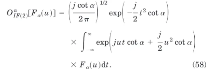
⫻ F␣共u兲dt. (58)
The SFRFT is similar to the original FRFT, except that the outside chirp term exp( ju2cot␣/2) is changed into exp(⫺ju2cot␣/2).
The type 2 SFRFT will have the advantage of simpler optical implementation. From Eqs. (38) and (41) we note that when a⫽ 1 or d ⫽ 1, then in Fig. 1 one of the lenses will have an infinite focal length and can be removed, and in Fig. 2 one of the free spaces will have zero length. So, when we use either Fig. 1 or Fig. 2 to implement the LCT, if we set a ⫽ 1 or d ⫽ 1 we can save one optical compo-nent. Then we consider the optical implementation of the fractional filter as shown in Fig. 3. If we set a ⫽ 1 and d⫽ ⫺1, for both b ⬎ 0 and b ⬍ 0 we can save one optical component in the left-hand system, and one in the in the right-hand system, for a total saving of two optical components. This is why we chose a ⫽ 1 and d ⫽ ⫺1 in Eq. (55).
When we substitute 兵a, b, c, d其⫽ 兵1, tan␣, ⫺2 cot ␣, ⫺1其into Eqs. (38) and (41), we obtain
for Fig. 1 f1→ ⬁, d0⫽ k tan␣,
f2⫽ 共k/2兲tan␣; (59)
for Fig. 2 d1⫽ k tan␣, f0⫽ 共k/2兲tan␣,
d2⫽ 0. (60)
That is, when we use the methods of Figs. 1 and 2 to implement the type 2 SFRFT, for Fig. 1 the first lens can be removed and for Fig. 2 the second free space can be re-moved. In as much as d0⫽ d1 and f2⫽ f0, for a type 2
SFRFT optical implementation by the method of Fig. 1 is the same as optical implementation by the method of Fig. 2, as we illustrate in Fig. 5. Note from Fig. 5 that the length of free space is always twice the focal length of the lens, no matter what the value of␣ is. The configuration of Fig. 5 is suitable when tan␣ ⬎ 0. When tan ␣ ⬍ 0, we can implement the LCT with parameters
兵⫺a, ⫺b, ⫺c, ⫺d其⫽兵⫺1, ⫺tan␣, 2 cot ␣, 1其 instead of
兵1, tan␣, ⫺2 cot ␣, ⫺1其.
Fig. 5. Optical implementation of the type 2 SFRFT (tan␣ ⬎ 0).
For the fractional filter system designed by a type 2 SFRFT we can use the system based on Fig. 3 and imple-ment the whole system as illustrated in Fig. 6 when tan␣ ⬎ 0, where
d⫽ k tan␣, f⫽ 共k/2兲tan␣. (61) When tan␣ ⬍ 0 we can use the implementation of Fig. 7 and the values of f and d will be
f ⫽ 共k/2兲兩tan␣兩, d⫽ k兩tan␣兩. (62) In that in both Figs. 6 and 7 the inverse system is the same as the forward system. So the two advantages of using a type 2 SFRFT are that we need only two lenses, two free spaces, and therefore a total of four optical com-ponents for a fractional filter and that the forward and the inverse systems have the same structure.
D. Type 3 SFRFT
The type 3 SFRFT is suitable for implementation of a GRIN medium. Suppose that a GRIN medium has the following refractive-index distribution:
n2共x, y兲 ⫽ n02关1 ⫺ 共nx/n0兲x2⫺ 共ny/n0兲y2兴,
nx, nyⰆ n0. (63)
And suppose that in Fig. 8 the field distribution at z ⫽ 0 is f0(x, y) and the field distribution at z⫽ L is
fL(x, y). Then the relationship between f0(x, y) and
fL(x, y) in Fig. 8 is18 fL共x, y兲 ⫽ exp
冉
⫺j 2n0L 冊
OFx 共ax,bx,cx,dx兲 ⫻兵OFy共ay,by,cy,dy兲关f 0共x, y兲兴其. (64)Here we use OFxand OFyto denote the one-dimensional
LCT along the x axis and the y axis, and
冋
ax bx cx dx册
⫽冋
cos wxsin ⫺sin wx cos册
,冋
ay by cy dy册
⫽冋
cos wysin ⫺sin wy cos册
, (65) where wx⫽ 共1/k兲共nxn0兲⫺1/2, wy⫽ 共1/k兲共nyn0兲⫺1/2, ⫽ L共nx/n0兲1/2, ⫽ L共ny/n0兲1/2. (66)So the effect of the GRIN medium is similar to that of a FRFT, except that here sin␣ is converted into wxsin␣
and⫺sin␣ is converted into ⫺sin ␣/wx. It seems that we
can define the new type of FRFT according to the follow-ing conversions:
OF共3兲关 f共t兲兴 ⫽ OF
共cos ,wxsin,⫺sin /wx,cos兲关 f共t兲兴,
⭓ 0, i.e., L⭓ 0. (67) Type 3 SFRFT: ( Ð 0)
So the definition of the type 3 SFRFT is
OF共3兲关 f共t兲兴 ⫽
冉
csc j2wx冊
1/2 exp冉
j 2wx u2cot冊
⫻冕
⫺⬁ ⬁ exp冉
⫺jutcsc wx ⫹ j 2wx t2cot冊
⫻ f共t兲dt. (68)We call Eq. (68) a type 3 SFRFT. Although the type 3 SFRFT seems very similar to the original FRFT, we have shown that for filter design the ratio b/a is important and that for the type 3 FRFT
b/a⫽ wxtan. (69)
So the type 3 FRFT with order is different from the original FRFT of order ␣ for design of fractional filters. Instead, it is equivalent to the original FRFT with order ␣, and the relationship between and ␣ is
␣ ⫽ tan⫺1共w
xtan兲 or ⫽ tan⫺1共wx⫺1tan␣兲. (70)
So, from Eqs. (67) and (70), if we want the GRIN medium to act as a FRFT of order␣ in the x axis, then the length of the GRIN medium should be
L⫽ 共n0/nx兲1/2tan⫺1共wx⫺1tan␣兲. (71)
Now we discuss the inverse of the type 3 SFRFT. In-asmuch as
冋
cos wxsin ⫺wx⫺1sin cos册
⫺1 ⫽冋
wcos ⫺wxsin x ⫺1sin cos册
⫽冋
⫺wcos共⫺兲 wxsin共⫺兲 x ⫺1sin共⫺兲 cos共⫺兲册
,it would seem that the inverse of the type 3 SFRFT with parameter would be the type 3 SFRFT with parameter ⫺. But, because length L of the GRIN medium should be nonnegative and in Eq. (67) L is negative when
Fig. 6. Filter designed by the type 2 SFRFT (tan␣⬎ 0).
Fig. 7. Filter designed by the type 2 SFRFT when tan␣⬍ 0.
⬍ 0, we use 2 ⫺ instead of . So the inverse of the type 3 SFRFT with parameter is the type 3 SFRFT with parameter 2 ⫺( ⬎ 0):
OF2⫺共3兲 兵OF共3兲关 f共t兲兴其⫽ f共t兲. (72) The type 3 SFRFT will have the additive, periodic prop-erties
OF共3兲兵OF共3兲关 f共t兲兴其⫽ OF共3兲兵OF共3兲关 f共t兲兴其⫽ OF⫹共3兲关 f共t兲兴,
(73)
OF共3兲关 f共t兲兴 ⫽ OF⫹2共3兲 关 f共t兲兴. (74)
We note that, although other SFRFTs’ introduced in this paper will have no additive and periodic properties, these properties will exist for the type 3 SFRFT. This is the advantage of the type 3 SFRFT and hence is the advan-tage of using the GRIN medium to implement the frac-tional filter. Because of these properties, when we use the GRIN medium to design the fractional filter the total length of the system is independent of the value of.
The fractional filter system design by the type 3 SFRFT can be written as
x0共t兲 ⫽ OF2⫺共3兲 兵OF共3兲关xi共t兲兴H共u兲其, (75)
or
x0共⫺t兲 ⫽ OF⫺共3兲兵OF共3兲关xi共t兲兴H共u兲其, ⬍ , (76)
and it can be implemented by the GRIN medium as shown in Fig. 9, where the values of L1and L2 are
L1⫽ 共n0/nx兲1/2, L2⫽ 共 ⫺兲共n0/nx兲1/2. (77)
We use x0(⫺t) instead of x0(t) as the output to reduce the
length of the GRIN medium. Because, from Eq. (67), length L of the GRIN medium is proportional to order, and, if we use x0(t) as the output, we must use the type 3
SFRFT with order 2 ⫺ for the inverse transform and a larger value of L2 will be required. We also note that,
if the thickness of filter H(u) is not considered, the total length of the filter system in Fig. 9 will be L1⫹ L2
⫽ (n0/nx)1/2and will always be independent of. The
fixed size of the implementation is the advantage that we derive using the GRIN medium to implement the frac-tional filter.
For the fractional filter of Fig. 9 the value of is con-strained in the range (0⬍ ⬍ ). This seems to be a restriction. But, for the type 3 SFRFT, cot␣ ⫽ wxtan
(␣ is of the order of the FRFT), so we can obtain all the values of ␣ by varying just in the range (0 ⬍ ⬍ ). So we can still use the type 3 SFRFT to implement the fractional filter for any value of␣.
E. Type 4 SFRFT
The type 4 SFRFT is suitable when we use the radar sys-tem to implement the FRFT. The relationship between the monochromic light propagating between the spherical
emitters and receivers and the LCT was discussed in de-tail in Ref. 19. Suppose that there are two spherical disks, A and B, as in Fig. 10, where RA and RB are the
radii of the spherical disks A and B, respectively, and D is the distance between the vertices of disks A and B. If the field distribution on disk A is FA(x, y) and the field
dis-tribution on disk B is FB(s, h), then, as was discussed in
Ref. 19, the relationship between FA(x, y) and FB(s, h):
FB共k, h兲 ⫽ exp共⫺j2D⫺1兲OSx
共RA,RB,D兲
⫻兵OSy共RA,RB,D兲关F
A共x, y兲兴其, (78)
where the one-dimensional transform OSx(RA,RB,D)is
OSx共RA,RB,D兲关 f共x兲兴 ⫽
冑
j Dexp冋
⫺ j 共RB⫺1⫹ D⫺1兲s2册
冕
⫺⬁ ⬁ exp冋
j2 D sx ⫹ j 共RA⫺1⫺ D⫺1兲s2册
f共x兲dx, D ⫽ 0, (79) OSx共RA,RB,0兲关 f共x兲兴 ⫽ exp冋
j 共RA⫺1⫺ RB⫺1兲s2册
f共s兲, D⫽ 0, (80)and OSy(RA,RB,D)关 f( y)兴 is of the same form as O
Sx
(RA,RB,D)
⫻ 关 f(x)兴, except that the variables 兵x, k其 are changed into 兵y, h其. We note that OSx
(RA,RB,d) is just the LCT with the
parameters
冋
a b c d册
⫽冋
1⫺ RA⫺1D ⫺D/k k共RA⫺1⫺ RB⫺1⫹ R⫺1A RB⫺1D兲 1 ⫹ RB⫺1D册
. (81) So we can use the radar system to implement the LCT, and, as length D should be nonnegative, we can use the radar system to implement the LCT whenb ⭐ 0. (82)
We already know that the ratio b/a will affect the prop-erties of the fractional filter designed by the LCT. In Eq. (81), b a ⫽ k ⫺1共R A ⫺1⫺ D⫺1兲⫺1. (83)
We can fix the value of RAand adjust length D of the free
space according Eq. (84) as below to obtain the desired value of b/a. Here we decide to set the relationship be-tween RAand D as
RA⫽ D/2 (84)
Fig. 9. GRIN medium implementation of the fractional filter de-signed by the type 3 SFRFT.
Fig. 10. This system contains two spherical disks and one free space.
to make the value of a be⫺1. Also, the value of RBwill
have no effect on the fractional filter, so we can set RBto
be any value. We choose
RB→ ⬁. (85)
After substituting Eq. (84) and relation (85) into Eq. (81), we obtain
冋
a b c d册
⫽冋
⫺1 ⫺D/k 2k/D 1
册
, so we can define the type 4 SFRFT as Type 4 SFRFT OF共D兲共4兲关 f共x兲兴 ⫽冑
j Dexp冉
⫺ jk 2Ds 2冊
⫻冕
⫺⬁ ⬁ exp冉
jk Dsx⫹ jk 2Dx 2冊
f共x兲dx. (86) Since b/a⫽ D/k, we can use the value of D to control the effects of the type 4 SFRFT for the design of the fractional filter. To make the type 4 SFRFT have the same effects as the original FRFT of order␣ for the design of the frac-tional filter we can setD ⫽ k tan␣. (87)
Then we discuss a fractional filter designed by the type 4 SFRFT. Inasmuch as
f共⫺x兲 ⫽ OF共D兲共4兲兵OF共D兲共4兲关 f共x兲兴其, (88)
the inverse of the type 4 SFRFT with parameter D is just the forward type 4 SFRFT with parameter D itself. And the formula for the fractional filter system designed by the type 4 SFRFT is
f0共⫺x兲 ⫽ OF共D兲共4兲兵O共D兲F共4兲共 fi共x兲兲H共s兲其. (89)
It can be implemented as in Fig. 11. Note from Fig. 11 that there are only two spherical disks with radii that vary with D and hence vary with ␣. The other two spherical disks have infinite radii and can be replaced by plane receivers, which would lessen the cost of the imple-mentation. When the radar system is used to implement the fractional filter designed by the original FRFT, the four spherical disks will all have finite radii and can not be replaced by plane emitters or receivers, and the struc-tures of the forward and inverse transform systems will be different. So using the type 4 SFRFT will indeed make the implementation of the fractional filter by the ra-dar system much simpler.
3. SFRFT FOR FRACTIONAL
CORRELATION
In Section 2 we discussed the conditions under which the LCT will have the same effects as the FRFT with order␣ for filter design, and we used the result to simplify the FRFT for digital computation and optical, GRIN-medium, and radar-system implementation. In this section we discuss under what conditions the LCT will have the same effects as the FRFT with order␣ for fractional cor-relation and use these results to define other types of the simplified FRFT.
A. Canonical Correlation and Effects of the Parameters Fractional correlation20,21is defined as
Ocorrp,q,r关x共t兲, y共t兲兴 ⫽ OFr
再
OFp关x共t兲兴OFq关 y共t兲兴冎
, (90)where the overbar means complex conjugation and cot p ⫹ cot r ⫽ cot q. (91) It has been used for space-variant pattern recognition.21
It can not only find the objects that are the same as the reference pattern but also predict whether these objects will be in a certain region. In Ref. 22 the use of fractional correlation for scaled pattern recognition, that is, detect-ing the objects that have the same scale as the reference, is discussed.
We can further generalize the fractional correlation into a canonical correlation by replacing the FRFT’s with LCT’s:
Ocorr共a,b,c,d兲,共e,f,g,h兲共m,n,s,v兲关x共t兲, y共t兲兴
⫽ OF共m,n,s,v兲
再
OF共a,b,c,d兲关x共t兲兴OF共e,f,g,h兲关 y共t兲兴冎
. (92)Because we have not seen the canonical correlation dis-cussed in easier papers, we discuss it in detail here. If we use z(t) to denote the output of the canonical correla-tion of x(t) and y(t), then
z共t兲 ⫽ 1 2
冉
j 2bfn冊
1/2 exp冉
jv 2nt 2冊
⫻冕
⫺⬁ ⬁ exp冉
⫺j nut⫹ jm 2nu 2冊
exp冉
ja 2bu 2冊
⫻冕
⫺⬁ ⬁ exp冉
⫺j but ⫹ ja 2bu 2冊
x共兲d exp冉
⫺jk 2 fu 2冊
⫻冕
⫺⬁ ⬁ exp冉
j fu⫺ je 2 f 2冊
y共n兲ddu ⫽ 1 2冉
j 2bfn冊
1/2 exp冉
jv 2nt 2冊
⫻冕
⫺⬁ ⬁冕
⫺⬁ ⬁ exp冉
ja 2b 2⫺ je 2 f 2冊
⫻冕
⫺⬁ ⬁ exp冋
ju冉
⫺t n⫺ b ⫹ f冊册
⫻ exp冋
j 2冉
n m ⫹ d b ⫺ h f冊
u 2册
dux共兲y共兲d d. (93)Fig. 11. Radar system to implement the fractional filter (de-signed by type 4 SFRFT).
We require that d b ⫹ m n ⫽ h f. (94) Then z共t兲 ⫽
冉
j 2bfn冊
1/2 exp冉
jv 2nt 2冊
⫻冕
⫺⬁ ⬁冕
⫺⬁ ⬁ exp冉
ja 2b 2⫺ je 2 f 2冊
⫻ ␦冉
⫺t n⫺ b ⫹ f冊
x共兲y共兲d d ⫽冉
jf 2bn冊
1/2 exp冉
jv 2nt 2冊
⫻冕
⫺⬁ ⬁ exp冋
ja 2b 2⫺ jef 2冉
t n ⫹ b冊
2册
⫻ x共兲y*冉
ft n ⫹ f b冊
d ⫽冉
jf 2bn冊
1/2 exp冋
j共vn ⫺ ef 兲 2n2 t 2册
⫻冕
⫺⬁ ⬁ exp冋
j共ab ⫺ ef 兲 2b2 2⫺ j ef nbt册
⫻ x共兲y*冉
ft n ⫹ f b冊
d, (95) 兩z共t兲兩 ⫽冉
兩 f 兩 2兩bn兩冊
1/2冏
冕
⫺⬁ ⬁ exp冋
j共ab ⫺ ef 兲 2b2 2 ⫺ j ef nbt册
x共兲y*冉
ft n ⫹ f b冊
d冏
. (96)Then suppose that y(t) is the scaling of x(t) with dis-placement t0: y共t兲 ⫽ x
冋
b f 共t ⫺ t0兲册
. (97) Then 兩z共t兲兩 ⫽冉
兩 f 兩 2兩bn兩冊
1/2冏
冕
⫺⬁ ⬁ exp冋
j共ab ⫺ ef 兲 2b2 2 ⫺ j ef nbt册
x共兲x*冉
⫹ b nt⫺ b f t0冊
d冏
, (98)冏
z冉
n f t0冊
冏
⫽冉
兩 f 兩 2兩bn兩冊
1/2 ⫻冏
冕
⫺⬁ ⬁ exp冋
j共ab ⫺ ef 兲 2b2 2⫺ je bt0册
⫻ 兩x共兲兩2d冏
. (99) When ab ⫽ ef,冏
z冉
n f t0冊
冏
⫽冉
兩 f 兩 2兩bn兩冊
1/2冏
冕
⫺⬁ ⬁ exp冉
⫺je bt0冊
兩x共兲兩 2d冏
; (100) and when ab ⫽ ef,冏
z冉
n f t0冊
冏
⫽冉
兩 f 兩 2兩bn兩冊
1/2冏
冕
⫺⬁ ⬁ exp冋
je 2 2共ab ⫺ ef 兲 ⫻冉
t0⫺ ab ⫺ ef be 冊
2册
兩x共兲兩2d冏
. (101)If we want兩z(nt0/f )兩 [i.e., the peak of 兩z(t)兩] to be
suffi-ciently large, the phase of the exponential term should be restricted in the range [⫺, ]. Thus when
ab ⫽ ef,
if y(t) is the scaling of x(t) with the factor f/b with some displacement, i.e., y(t)⫽ x关b(t ⫺ t0)/f兴, and
displace-ment t0is in the range
⫺
冏
B b e冏
⬍ t0⬍冏
B b e冏
, (102) where B is defined as x共t兲 ⬇ 0, 兩t兩 ⬎ B, (103) then兩z(t)兩 will have its peak at t⫽ nt0/f with no seriousdistortion. But, when
ab ⫽ ef,
if y(t) is the scaling of x(t) with the factor f/b with some displacement, i.e., y(t) ⫽ x关b(t ⫺ t0)/f兴, and the
dis-placement t0 is in the range
冏
a e ⫺ f b冏
B⫺冋
2冏
b e冉
a e ⫺ f b冊
冏
册
1/2 ⬍ t0⬍冋
2冏
b e冉
a e ⫺ f b冊
冏
册
1/2 ⫺冏
a e ⫺ f b冏
B, (104)then兩z(t)兩 will have its peak at t⫽ nt0/f with no serious
distortion.
In other cases, the peak of兩z(t)兩 will have serious dis-tortion. So, if we choose the parameters properly, we can detect the objects that scale with the reference with a cer-tain scaling factor and are in a cercer-tain region. So we can use the canonical correlation for scaled shift-variant pat-tern recognition.
B. Type 5 SFRFT
When one uses canonical correlation for pattern recogni-tion, there are only two terms to be decided: the scaling ratio and the width of the region over which the object can be detected. But, for fractional correlation as in Eq. (92), there are a total of 12 parameters. It seems unnecessary to use so many parameters to control only two terms, so we can simplify the canonical correlation by reducing the number of parameters. We can set
• 兵m, n, s, v其⫽兵0, 1,⫺1, 0其. That is, the last LCT in Eq. (92) becomes the Fourier transform.
• a ⫽ e ⫽ 1.
• d⫽ h ⫽ 0. Then, as m⫽ d ⫽ h ⫽ 0, the con-straint of Eq. (94) will always be satisfied; and, as ad ⫺ bc ⫽ eh ⫺ fg ⫽ 1, c ⫽ ⫺1/b and g ⫽ ⫺1/f.
Now the number of parameters of canonical correlation is reduced from 12 to 2, and Eq. (92) can be rewritten as
Ocorrb,f关x共t兲, y共t兲兴 ⫽ FT
再
OF共1,b,⫺b⫺1,0兲关x共t兲兴 ⫻ OF共1,f,⫺f⫺1,0兲
关 y共t兲兴
冎
. (105) Equation (97) remains the same, and Eq. (99) is simplified as 兩z共 f⫺1t 0兲兩 ⫽冉
兩 f 兩 2兩b兩冊
1/2冏
冕
⫺⬁ ⬁ exp冋
j共b ⫺ f 兲 2b2 2⫺ j bt0册
⫻ 兩x共兲兩2d冏
. (106)And the conditions under which we can detect the objects are the following: When
b ⫽ f,
if y(t) is the displacement of x(t), i.e.,
y共t兲 ⫽ x共t ⫺ t0兲, (107)
then displacement t0 is in the range
⫺
冏
b B冏
⬍ t0⬍冏
b B冏
. (108) When b ⫽ f,if y(t) is the scaling of x(t) with the factor f/b with some displacement, i.e.,
y共t兲 ⫽ x关b共t ⫺ t0兲/f 兴, (109)
and displacement t0 is in the range
冏
1⫺ f b冏
B⫺冋
2冏
b冉
1⫺ f b冊
冏
册
1/2 ⬍ t0 ⬍冋
2冏
b冉
1 ⫺ f b冊
冏
册
1/2 ⫺冏
1⫺ f b冏
B, (110)then兩z(t)兩 will have its peak at t⫽ t0/f without serious
distortion.
The simplified canonical correlation has only two pa-rameters b and f, and we can use these two papa-rameters to control the two terms (the scaling ratio and the width of the detecting region). This is much simpler than the original canonical correlation and the original fractional correlation. We can choose the parameters according to the following model:
First, decide the scaling ratio [ ⫽ (width of the object)/(width of the reference)] and the width of detecting region T (which means that the object can be detected when ⫺T/2 ⬍ t0⬍ T/2, where t0 is the amount of
dis-placement).
Then, because f/b⫽ , and from inequalities (108) and (110), when ⫽ 1 we can choose b as
b ⫽ TB/2, (111)
and when ⫽ 1 we can choose b as
b ⫽ 1 2共1 ⫺ 兲
冉
T 2 ⫹ 兩1 ⫺兩B冊
2 . (112) Then we choose f as f⫽ b. (113)The process of deciding the parameters of the simpli-fied canonical correlation is much simpler than the origi-nal canonical correlation. When we want to change the width of the detection range or the scaling ratio, we can first adjust b according to Eq. (111) or (112) and then ad-just f according to Eq. (113).
From the discussion above, we can define the SFRFT that is suitable for the fractional correlation. We can de-fine the type 5 SFRFT as
Type 5 SFRFT Fb共u兲 ⫽ OFb共5兲关 f共t兲兴 ⫽ 共 j2b兲⫺1/2
冕
⫺⬁ ⬁ exp冉
⫺j but⫹ j 2bt 2冊
f共t兲dt, (114) which corresponds to a LCT with the parameters兵1, b, ⫺b⫺1, 0其, and its inverse is the LCT with the pa-rameters兵0,⫺b, b⫺1, 1其: f共t兲 ⫽ OIFb 共5兲关Fb共u兲兴 ⫽
冉
j 2b冊
1/2 exp冉
⫺ j 2bt 2冊
冕
⫺⬁ ⬁ exp冉
j btu冊
Fb共u兲du. (115) From the definition of the type 5 SFRFT we can rewrite Eq. (92) and define the fractional correlation asOcorrb,f关x共t兲, y共t兲兴 ⫽ FT
再
ObF共5兲关x共t兲兴OFf共5兲关 y共t兲兴冎
, (116)which is essentially the same as Eq. (105).
The most important advantage in using the type 5 SFRFT is that it is simpler to use for fractional correla-tion than the original FRFT, and the performance re-mains the same. Because in Eq. (105) d, h, m, and v are all set to 0, when using the type 5 SFRFT for fractional correlation, we can save four chirp multiplication opera-tions. And, from Eq. (111) or (112), the relationship be-tween parameter b and the width of the detection region
T is quite simple, and we can use b to control the width of
the detection region. But, for the original fractional cor-relation, the relationship between the parameters and the width of the detection region is complex, and it is harder in practice to use the parameters to control that width.
Some interesting properties of the type 5 SFRFT are listed here:
OFb共5兲(OFb共5兲兵OFb共5兲关h共t兲兴其)⫽ h共⫺t兲 any b, (117)
i.e.,
OIFb 共5兲关h共u兲兴 ⫽ OFb共5兲兵OFb共5兲关h共⫺u兲兴其 any b. (118)
• Modulation property:
OFb共5兲关exp共 jvt兲f共t兲兴 ⫽ Fb共u ⫺ bv兲. (119)
This property is similar to the modulation property of the original Fourier transform, except that the shift in fre-quency domain is magnified b.
• Multiplication property:
OFb共5兲关tf共t兲兴 ⫽ jbFb⬘共u兲. (120)
This property is similar to the multiplication of the origi-nal Fourier transform.
4. SUMMARY AND CONCLUSIONS
We summarize the properties of SFRFT’s introduced in this paper. • Type 1 SFRFT: Fa共u兲 ⫽ 共 j2兲⫺1/2
冕
⫺⬁ ⬁ exp冉
⫺jut ⫹ j 2cot␣t 2冊
f共t兲dt.This equation corresponds to the LCT with parameters
兵a, b, c, d其⫽兵cot␣, 1, ⫺1, 0其. It can be used for a frac-tional filter implemented by a digital implementation or optical system. • Type 2 SFRFT: Fa共u兲 ⫽
冉
cot␣ j2冊
1/2 exp冉
⫺j 2u 2cot␣冊
⫻冕
⫺⬁ ⬁exp
冉
⫺jut cot␣ ⫹ j 2t2cot␣
冊
f共t兲dt.This equation corresponds to the LCT with parameters
兵a, b, c, d其⫽兵1, tan␣, ⫺2 cot ␣, ⫺1其. It can be used for a fractional filter implemented by an optical system.
• Type 3 SFRFT: F共u兲 ⫽
冉
csc j2wx冊
1/2 exp冉
j 2wx u2cot冊
⫻冕
⫺⬁ ⬁ exp冉
⫺jutcsc wx ⫹ j 2wx t2cot冊
⫻ f共t兲dt, ⫽ tan⫺1共w x ⫺1tan␣兲.This equation corresponds to the LCT with parameters
兵a, b, c, d其⫽ 兵cos, wxsin, ⫺sin /wx, cos其. It can
be used for a fractional filter implemented by a GRIN me-dium. • Type 4 SFRFT: FD共u兲 ⫽
冑
j Dexp冉
⫺ jk 2Du 2冊
冕
⫺⬁ ⬁ exp冉
jk Dut ⫹ jk 2Dt 2冊
⫻ f共t兲dt, D ⫽ 2 tan␣/.This equation corresponds to the LCT with parameters
兵a, b, c, d其⫽ 兵⫺1, ⫺D/k, 2k/D, 1其. It can be used for a fractional filter implemented by a radar system.
• Type 5 SFRFT: Fb共u兲 ⫽ OFb共5兲关 f共t兲兴 ⫽ 共 j2b兲⫺1/2
冕
⫺⬁ ⬁ exp冉
⫺j but⫹ j 2bt 2冊
f共t兲dt.This equation corresponds to the LCT with parameters
兵a, b, c, d其⫽ 兵1, b, ⫺b⫺1, 0其. It can be used for a frac-tional correlation with digital implementation.
In Table 1 we show the complexity of implementation of the fractional Fourier transform (FRFT) and the simpli-fied fractional Fourier transforms (SFRFT’s) introduced in this paper. From this table we can see the advantages for each type of SFRFT. We have discussed under what conditions the linear canonical transform (LCT) will have the same effects as the original FRFT on the design of a fractional filter and fractional correlation. And we have used these results to define five types of SFRFT. These SFRFT’s are simpler than the original FRFT for digital computation and optical, gradient-index medium, and Table 1. Comparison of Implementation Complexity of Fourier-Transform Types Analyzed in This Study
Type of Fourier
Transform Digital Computation Optical System GRIN Medium Radar System
Original FRFT
2P⫹ (P/2) log2P 2 lenses,
1 free space or 1 lens, 2 free spaces
GRIN medium
with other components
2 spherical disks, 1 free space
Type 1 SFRFT
P⫹ (P/2) log2P Same as the original but only 1 component, which varies with␣
Same as the original Same as the original
Type 2 SFRFT
Same as the original 1 lens, 1 free space Same as the original Same as the original Type 3
SFRFT
Same as the original Same as the original GRIN medium only Same as the original Type 4
SFRFT
Same as the original Same as the original Same as the original 1 spherical disk, 1 plane, 1 free space Type 5
SFRFT
radar-system implementation. But these SFRFT’s retain the same capabilities as the original FRFT for design of a fractional filter or for fractional correlation.
Our goals in this paper have been to search for the transform with the simplest implementation and to pre-serve the capabilities of the original FRFT. Thus, al-though these SFRFT’s usually have no additivity proper-ties they are useful for the practical applications. We have described five types of SFRFT. We can also derive the other types of simplified FRFT for other special appli-cations, special implementations, or other requirements. The SFRFT’s have high potential, and may replace the the original FRFT in many applications such as filter de-sign and pattern recognition.
ACKNOWLEDGMENT
This work was supported by the National Science Coun-cil, Republic of China, under contract NSC 89-2213-E-002-092.
S.-C. Pei’s e-mail address is [email protected].
REFERENCES
1. V. Namias, ‘‘The fractional order Fourier transform and its application to quantum mechanics,’’ J. Inst. Math. Appl. 25, 241–265 (1980).
2. L. B. Almeida, ‘‘The fractional Fourier transform and time-frequency representations,’’ IEEE Trans. Signal Process.
42, 3084–3091 (1994).
3. M. Moshinsky and C. Quesne, ‘‘Linear canonical transfor-mations and their unitary representations,’’ J. Math. Phys.
12, 1772–1783 (1971).
4. K. B. Wolf, Integral Transforms in Science and Engineering (Plenum, New York, 1979), Chap. 9.
5. S. Abe and J. T. Sheridan, ‘‘Optical operations on wave functions as the Abelian subgroups of the special affine Fourier transformation,’’ Opt. Lett. 19, 1801–1803 (1994). 6. L. M. Bernardo, ‘‘ABCD matrix formalism of fractional
Fou-rier optics,’’ Opt. Eng. 35, 732–740 (1996).
7. H. M. Ozaktas and D. Mendlovic, ‘‘Every Fourier optical system is equivalent to consecutive fractional-Fourier-domain filtering,’’ Appl. Opt. 35, 3167–3170 (1996). 8. S. C. Pei and J. J. Ding, ‘‘Closed form discrete fractional
and affine Fourier transforms,’’ IEEE Trans. Signal Pro-cess. 48, 1338–1353 (2000).
9. H. M. Ozaktas, O. Arikan, M. A. Kutay, and G. Bozdagi, ‘‘Digital computation of the fractional Fourier transform,’’ IEEE Trans. Signal Process. 44, 2141–2150 (1996). 10. A. M. Almanasreh and M. G. Abushagur, ‘‘Fractional
corre-lation based on the modified fractional order Fourier trans-form,’’ Opt. Eng. 37, 175–184 (1998).
11. M. A. Kutay, H. M. Ozaktas, O. Arikan, and L. Onural, ‘‘Op-timal filter in fractional Fourier domains,’’ IEEE Trans. Signal Process. 45, 1129–1143 (1997).
12. A. W. Lohmann, D. Mendlovic, and Z. Zalevsky, ‘‘Fractional Hilbert transform,’’ Opt. Lett. 21, 281–283 (1996). 13. H. M. Ozaktas, B. Barshan, D. Mendlovic, and L. Onural,
‘‘Convolution, filtering, and multiplexing in fractional Fou-rier domains and their rotation to chirp and wavelet trans-form,’’ J. Opt. Soc. Am. A 11, 547–559 (1994).
14. S. C. Pei and J. J. Ding, ‘‘Relations between the fractional operations and the Wigner distribution, ambiguity func-tion,’’ submitted to IEEE Trans. Signal Process.
15. L. B. Almeida, ‘‘Product and convolution theorems for the fractional Fourier transform,’’ IEEE Signal Process. Lett. 4, 15–17 (1997).
16. A. I. Zayed, ‘‘A convolution and product theorem for the fractional Fourier transform,’’ IEEE Signal Process. Lett. 5, 101–103 (1998).
17. B. Barshan, M. A. Kutay, and H. M. Ozaktas, ‘‘Optimal fil-tering with linear canonical transformations,’’ Opt. Com-mun. 135, 32–36 (1997).
18. L. Yu, M. Huang, L. Wu, Y. Lu, W. Huang, M. Chen, and Z. Zhu, ‘‘Fractional Fourier transform and the elliptic gradient-index medium,’’ Opt. Commun. 152, 23–25 (1998). 19. P. Pellat-Finet and G. Bonnet, ‘‘Fractional order Fourier transform and Fourier optics,’’ Opt. Commun. 111, 141–154 (1994).
20. D. Mendlovic, H. M. Zalevsky, and A. W. Lohmann, ‘‘Frac-tional correlation,’’ Appl. Opt. 34, 303–309 (1995). 21. A. W. Lohmann, Z. Zalevsky, and D. Mendlovic, ‘‘Synthesis
of pattern recognition filters for fractional Fourier process-ing,’’ Opt. Commun. 128, 199–204 (1996).
22. S. Granieri, R. Arizaga, and E. E. Sicre, ‘‘Optical correlation based on the fractional Fourier transform,’’ Appl. Opt. 36, 6636–6645 (1997).