Infrared Brazing of Ti-6Al-4V and 17-4 PH Stainless Steel
with a Nickel Barrier Layer
R.K. SHIUE, S.K. WU, C.H. CHAN, and C.S. HUANG
Infrared brazing of Ti-6Al-4V and 17-4 PH stainless steel using the BAg-8 filler metal was performed in this study. A nickel barrier layer 10 mm thick was introduced on the 17-4 PH stainless steel before infrared brazing. For the specimen that was infrared brazed at 800 °C and 850 °C for less than 300 seconds, the Ni layer served as an effective barrier layer to prevent the formation of Ti-Fe interme-tallics. Experimental results show that the average shear strength of the joint can be greatly improved for the specimen by Ni plating. Comparing the specimens with and without electroless-plated Ni film, the former has no Ti-Fe intermetallic compound, but interfacial CuNiTi and NiPTi phases are observed in the latter. The fractured location of the joint after the shear test is changed from the interfacial TiFe (without Ni plating) into the TiCu reaction layer (with Ni plating). The plated Ni layer is consumed for the specimen that was infrared brazed at 880 °C for 300 seconds, and its bonding strength is impaired. Consequently, a lower brazing temperature and/or time are still pre-ferred even though a plated Ni barrier layer is applied.
I. INTRODUCTION
T
HE dissimilar joining of Ti-6Al-4V and 17-4 PH stain-less steel (17-4 PH SS) is potentially applied in the manu-facture of golf club heads. The combination of a less expensive 17-4 PH SS body and an expensive Ti-6Al-4V striking plate makes an attractive product for many manu-facturers. However, it is difficult to form a reliable metal-lurgical bond between Ti-6Al-4V and 17-4 PH SS due to the high reactivity of titanium. Titanium is readily reacted with several other elements and forms brittle intermetallics in the brazed joint.[1,2,3]Accordingly, adhesive bonding or mechanical fastening is currently applied in joining the Ti alloy and 17-4 PH SS.Brazing is often considered as one of the best choices in dissimilar bonding. It has been reported that the titanium alloy is successfully brazed with many silver-based braze alloys.[3–6] 72Ag-28Cu (wt pct) is a eutectic silver-based braze alloy with a melting point of 780 °C. Based on the AWS specification for braze alloys, it is found consistent with the BAg-8 braze alloy.[3]The silver-based braze alloy is suitable in brazing steels, stainless steels, titanium alloys, and refractory metals.[1,3] Accordingly, it has been chosen as the filler metal in brazing Ti-6Al-4V and 17-4 PH SS.
Infrared brazing makes use of infrared energy generated by heating a tungsten filament in a quartz tube as the heat-ing source, and it features an extraordinarily high heatheat-ing rate of about 3000 °C/min.[4,7]The infrared rays can easily transmit through the quartz tube, as quartz is transparent for infrared light. By means of an appropriate optical focusing system, local heating of the bonding surfaces can be easily
achieved. Accordingly, infrared brazing is characterized by both its fast thermal history and high-energy efficiency, making it very promising for brazing. The interfacial reac-tion among the molten braze and substrates during infrared brazing may be greatly decreased due to its rapid thermal history. Several infrared-brazed joints have been reported in the literature.[7,8,9] Alternatively, the interfacial reaction among the molten braze and both the substrates during brazing can also be alleviated or avoided by using a barrier layer coated on the substrate.[10–14]A barrier layer can iso-late or abate the interfacial reaction between the molten braze and the substrate during brazing. Therefore, it is expected that the bonding strength can be further improved with the proper selection of coating(s) on the substrate. Electroless or electric plating on a titanium alloy is difficult to achieve using commercially available methods. In con-trast, excellent electroless Ni plating on the 17-4 PH SS can be easily performed in the industry. Also, the Ag-Cu eutec-tic braze demonstrates good wettability on the Ni, and a thin layer of plated nickel also exhibits excellent adhesion on the 17-4 PH SS substrate.[1] Consequently, it was selected as the barrier layer in the experiment.
The focus of this research is on the infrared brazing of Ti-6Al-4V and 17-4 PH SS using the BAg-8 braze alloy. Electroless nickel plating with a thickness of 10 mm is applied on the surface of 17-4 PH SS substrate as the bar-rier layer before infrared brazing. Also, the 17-4 PH SS without Ni plating is included in the experiment for the purpose of comparison. Microstructural evolution, interfa-cial reaction, and shear strength of the infrared brazed joint are widely assessed in the study.
II. EXPERIMENTAL PROCEDURES The base metals used in the experiment were Ti-6Al-4V and 17-4 PH SS plates with a thickness of 3 mm each. Some 17-4 PH SS plates were electroless plated with a 10-mm-thick nickel layer. BAg-8 foils with a thickness of 50 and 100 mm were applied as the brazing filler metal. The heating rate used in infrared brazing was set at 900 °C/min throughout the experiment. All samples were preheated to R.K. SHIUE, Associate Professor, and S.K. WU, Professor, are with the
Department of Materials Science and Engineering, National Taiwan Uni-versity, Taipei 106, R.O.C. Taiwan. Contact e-mail: [email protected] C.H. CHAN, Engineer, formerly with the Institute of Mechanical Engineering, National Taiwan University, is now with the Chung-Shan Institute of Sci-ence and Technology, Tao-Yuan, R.O.C. Taiwan. C.S. HUANG, Sergeant, formerly with the Institute of Mechanical Engineering, National Taiwan University, is now with the Chinese (Taiwan) Army, Tao-Yuan, R.O.C. Taiwan.
600 °C for 90 seconds before heating up to the brazing temperature. Table I summarizes all process variables used in the experiment. After infrared brazing, the cross-sections of the brazed specimens were examined using either LEO 1530 field emission scanning electron microscope or PHILIPS* XL-30 scanning electron microscope (SEM) *PHILIPS is a trademark of Philips Electronic Instruments Corp., Eindhoven, The Netherlands.
with an accelerating voltage of 15 kV. Quantitative chemical analyses were performed using a JEOL** JXL-8800M
**JEOL is a trademark of Japan ElectronOptics Ltd., Tokyo. electron probe microanalyzer with an operating voltage of 20 kV and spot size of 1 mm.
Shear tests were performed to evaluate the bonding strength of selected infrared brazed joints.[4,6,9]A Shimadzu AG-10 universal testing machine compressed the infrared-brazed specimen with a constant speed of 0.5 mm/min. The fractured surface obtained after the shear test was examined using SEM, and the cross-section of the brazed joint was
performed to locate the fracture location. X-ray structural analyses were carried out on selected fractured surfaces using a Philips PW1710 X-Ray diffractometer. The Cu Ka was selected as the X-ray source. The X-ray scan rate
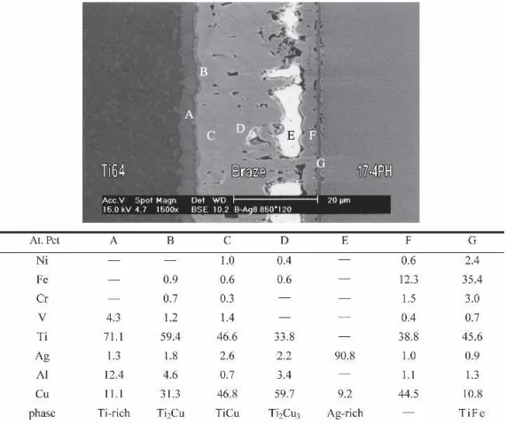
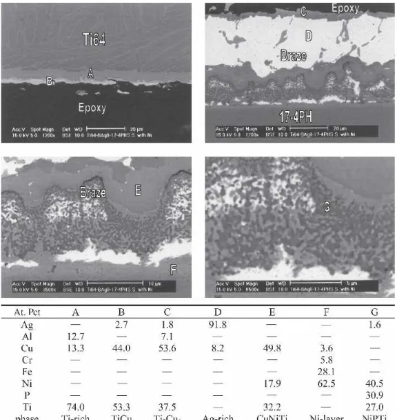
Fig. 1—SEM BEI and EDS chemical analysis results (in at. pct) of infrared-brazed Ti-6Al-4V and 17-4 PH SS using BAg-8 braze alloy at 800 °C for 120 seconds.
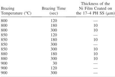
Table I. Summary Process Variables Used in the Infrared Brazing
Brazing
Temperature (°C) Brazing Time(sec)
Thickness of the Ni Film Coated on the 17–4 PH SS (mm) 800 120 — 800 180 10 800 300 10 850 120 — 850 180 10 850 300 — 850 300 10 880 180 10 880 300 10 900 30 — 900 120 — 900 300 —
was set at 4 deg/min, and its range was between 30 and 80 deg.
III. RESULTS AND DISCUSSION A. Infrared-Brazed Ti-6Al-4V and 17-4 PH SS Without Electroless Ni Plating
Figure 1 shows SEM backscattered electron imaging (BEI) and energy dispersive spectroscopy (EDS) chemical analysis results (in at. pct) of infrared-brazed Ti-6Al-4V and 17-4 PH SS using the BAg-8 braze alloy at 800 °C for 120 seconds. The infrared-brazed joint is mainly com-posed of primary Ag-rich and Ag-Cu eutectic phases. It is obvious that the copper content in the braze alloy prefer-entially reacts with Ti-6Al-4V substrate, resulting in inter-facial TiCu, Ti3Cu4, and TiCu4phases (marked as A, B, and C in the figure). The interfacial reaction layer between the braze alloy and 17-4 PH SS is rich in Fe, Ti, and Cu (marked by F), but its chemical composition cannot be accurately determined due to its width, which is less than 1 mm. The consumption of Cu from the brazed alloy results in a change of microstructure of the brazed joint from eutectic to proeutectic, as displayed in Figure 1.
As described earlier, the infrared brazing features a rapid thermal history. The microstructure of the brazed joint is significantly changed for increased brazing temperature and/or time. Figure 2 shows SEM BEI and EDS chemical analysis results (in at. pct) of infrared-brazed Ti-6Al-4V and 17-4 PH SS at 850 °C for 120 seconds. Both dissolution
of Ti-6Al-4V into molten braze and the reaction between Ti and Cu are greatly enhanced (Figures 1 and 2). Based on the EDS chemical analysis results, titanium-copper inter-metallic compounds (marked by B–D and F) dominate the entire infrared-brazed joint. The Ag-Cu eutectic disappears due to the strong reaction between Cu and Ti-6Al-4V sub-strate, and the amount of Ag-rich matrix (marked by E) is greatly decreased in the joint. A thin layer of TiFe (marked by G) is observed at the interface between the braze alloy and 17-4 PH SS substrate. The structural evidence of the interfacial TiFe phase will be given in the following X-ray analysis.
Figure 3 displays SEM BEI and EDS chemical analysis results (in at. pct) of infrared-brazed Ti-6Al-4V and 17-4 PH SS at 900 °C for 300 seconds. Equiaxed grains of the Ti-6Al-4V substrates are observed. The dissolution of Ti-6Al-4V substrate into molten braze is greatly enhanced at 900 °C, and the Ti-rich phase dominates the brazed joint (marked by A and B). According to the binary Cu-Ti phase diagram, the Ti-rich liquid experiences a peritectic reac-tion upon solidificareac-tion, and the maximum solubility of Cu in b-Ti is much greater than that in the a-Ti.[15] Alloying titanium with Cu results in a phase diagram at the Ti-rich end involving a eutectoid decomposition of the b-Ti—i.e., b-Ti / a-Ti 1 g, where g can be an intermediate com-pound, Ti2Cu.[16,17]The transformation of b-Ti is strongly related to the chemical composition of the b phase, anneal-ing temperature, and coolanneal-ing rate.[18,19,20]The brazed joint is mainly composed of eutectoid structure (Figure 3).
Fig. 2—SEM BEI and EDS chemical analysis results (in at. pct) of infrared-brazed Ti-6Al-4V and 17-4 PH SS using BAg-8 braze alloy at 850 °C for 120 seconds.
However, eutectoid a-Ti and Ti2Cu phases cannot be sim-ply identified by the simple EDS chemical analysis, and they need further investigation.
For the specimen infrared brazed at 900 °C, the silver content in the braze alloy overflows out of the brazed joint during brazing, with the observation of the interfacial Ti2Cu as well as Ti-rich phases in the joint (marked by C and D). Similar to the aforementioned results, a layer of Ti-Fe intermetallics is also found at the interface between the braze and 17-4 PH SS substrate. The thickness of Ti-Fe intermetallics is increased with increasing the brazing tem-perature and/or time (Figures 1, 2, and 3).
Table II shows the average shear strength of infrared-brazed Ti-6Al-4V and 17-4 PH SS without applied nickel coating on the 17-4 PH SS. It is obvious that the average shear strength of infrared-brazed joint is decreased upon increasing the brazing temperature and/or time. The speci-men infrared brazed at 800 °C for 120 seconds demon-strates the highest shear strength, up to 96 MPa. However, the average shear strength of the joint is as low as 22 MPa for the specimen infrared brazed at 900 °C for 300 seconds.
It is expected that the presence of an interfacial brittle intermetallic compound is detrimental to the bonding strength of the joint. Also, both species and morphologies of the intermetallics in the brazed joint have a strong effect Fig. 3—SEM BEI and EDS chemical analysis results (in at. pct) of infrared-brazed Ti-6Al-4V and 17-4 PH SS using BAg-8 braze alloy at 900 °C for 300 seconds.
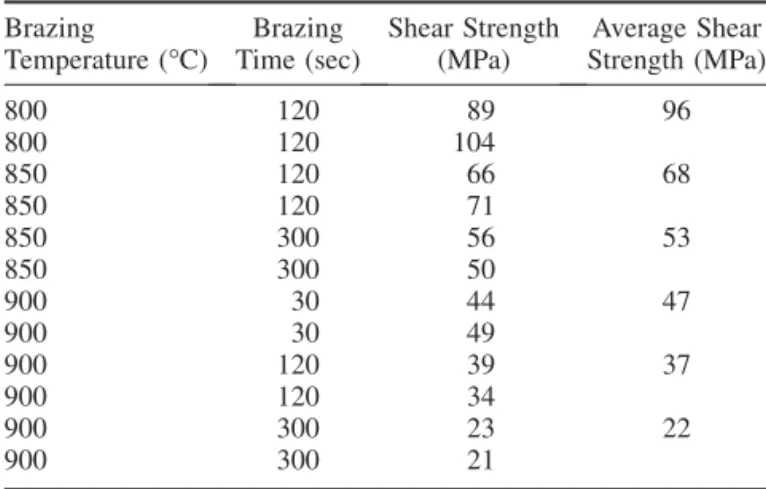
Table II. Shear Strength of Infrared-Brazed Ti-6Al-4V and 17-4 PH Without Ni Coating
Brazing
Temperature (°C) Time (sec)Brazing Shear Strength(MPa) Strength (MPa)Average Shear
800 120 89 96 800 120 104 850 120 66 68 850 120 71 850 300 56 53 850 300 50 900 30 44 47 900 30 49 900 120 39 37 900 120 34 900 300 23 22 900 300 21
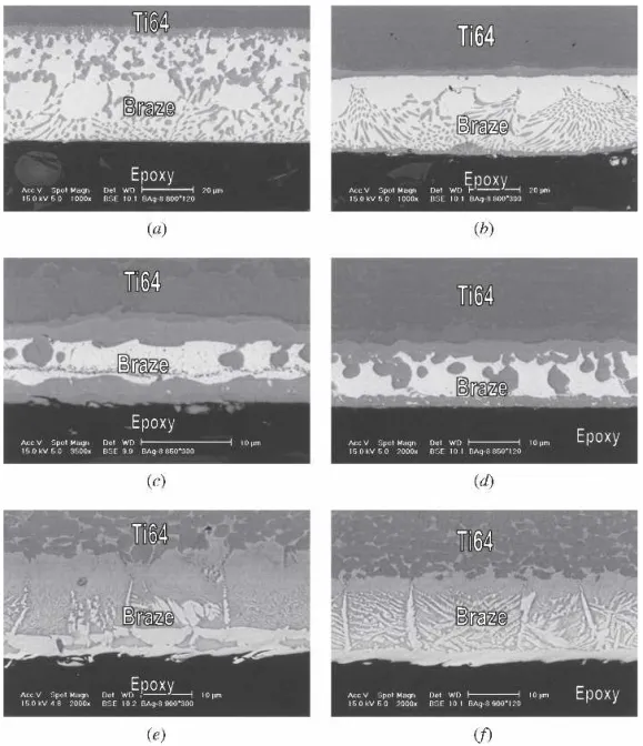
on its bonding strength. Figure 4 shows the cross-sections of Ti-6Al-4V/BAg-8/17-4 PH SS joints infrared brazed at various conditions after the shear test. The upper part of the figure is the Ti-6Al-4V side of the joint, and the 17-4 PH SS side is not included in this figure. The fracture in the joint is located at the interface between the braze alloy and 17-4 PH SS for all specimens. The interfacial reaction between the braze alloy and 17-4 PH SS is not prominent, but it greatly deteriorates the bonding strength of the joint. It is inferred that the presence of interfacial Ti-Fe intermetallics is detrimental to the shear strength of the brazed joint. Figure 5 displays the XRD structural analysis of the frac-tured surface after shear test infrared brazed at 850 °C for 300 seconds. The fractured surface mainly consists of TiFe, TiCu, and Ti2Cu3. Accordingly, the growth of these brittle intermetallic compounds, especially for the Ti-Fe interme-tallics, significantly deteriorates the bonding strength of the joint.
The use of infrared brazing cannot completely prohibit the formation of interfacial reaction layer(s). However, it provides an effective way to inhibit the growth of interme-tallics at the interface between the braze alloy and substrate when a low brazing temperature and a short brazing time are applied (Figure 1).
B. Infrared-Brazed Ti-6Al-4V and 17-4 PH SS with 10-mm Electroless Ni plating
Table III shows the average shear strength of infrared-brazed Ti-6Al-4V and 17-4 PH SS with 10-mm Ni coating. The average shear strength of the joint with Ni coating is significantly higher than that without Ni coating for all brazing conditions.For thespecimen infrared brazedat800 °Cor850 °C, the average shear strength is between 173 and 210 MPa. In contrast, the average shear strength is greatly decreased below 150 MPa for the specimen infrared brazed at 880 °C.
Fig. 4—Cross-sections of Ti-6Al-4V/BAg-8/17-4 PH joints after shear test infrared brazed at (a) 800 °C for 120 seconds, (b) 800 °C for 300 seconds, (c) 850 °C for 120 seconds, (d) 850 °C for 300 seconds, (e) 900 °C for 120 seconds, and (f) 900 °C for 300 seconds.
Fig. 5—XRD structural analyses of fractured surfaces after shear test infrared brazed at 850 °C for 300 seconds.
Table III. Shear Strength of Infrared-Brazed Ti-6Al-4V and 17-4 PH with a 10-mm Ni Coating
Brazing
Temperature (°C) Time (sec)Brazing Strength (MPa)Shear Strength (MPa)Average Shear
800 180 187 176 800 180 165 800 300 193 210 800 300 227 850 180 219 207 850 180 194 850 300 168 173 850 300 178 880 180 161 145 880 180 129 880 300 130 130 880 300 129
Fig. 6—Cross-sections of Ti-6Al-4V/BAg-8/17-4 PH joints after shear test infrared brazed at 800 °C for (a) and (b) 180 seconds and (c) and (d) 300 seconds.
It is clear that increasing the brazing temperature above 850 °C deteriorates the bonding strength of the brazed joint.
Figure 6 displays the cross-sections of the joints after shear test infrared brazed at 800 °C for 180 and 300 seconds. Different from the specimen without the Ni barrier layer, the fracture location is at the interface between Ti-6Al-4V
and braze for all specimens with a 10-mm layer. Based on the EDS chemical analysis results, TiCu (marked by B) and TiCu2(marked by C) are observed at the interface between the braze and Ti-6Al-4V. It is obvious that the strength of interfacial Ti-Cu intermetallic compounds is better than that of interfacial Ti-Fe intermetallics due to the higher average shear strength of the brazed joint.
The electroless nickel layer consists of Ni and P (marked by G in Figure 6(b)), and it demonstrates good adherence to both the braze alloy and 17-4 PH SS substrate. The electro-less Ni-plated layer does not contain Fe, the major content of the 17-4 PH SS, after infrared brazing. Therefore, the Ni barrier layer effectively inhibits the transport of Ti and Fe
between the molten braze and 17-4 PH SS during infrared brazing. There is an interfacial reaction layer (marked by F in Figure 6(b)), and its chemical composition is close to that of NiPTi, as demonstrated in Figure 7(a).[21] The Ti content dissolves from the Ti-6Al-4V substrate into the molten braze during brazing, and it readily reacts with
Fig. 8—Cross-sections of Ti-6Al-4V/BAg-8/17-4 PH joints after shear test infrared brazed at (a) through (d) 850 °C for 180 seconds and (e) and (f) 850 °C for 300 seconds.
the Ni barrier layer on the 17-4 PH SS, forming the inter-facial NiPTi reaction layer. Also, there is a phase rich in Cu, Ni, and Ti next to the interfacial NiPTi layer (marked by E in Figure 6(b)). According to the isothermal section of Cu-Ni-Ti ternary phase diagram shown in Figure 7(b), its chemical composition is close to that of CuNiTi interme-tallics.[21]Both the interfacial CuNiTi and NiPTi phases are free from Fe content, the major constituent of 17-4 PH SS. Because the nickel barrier layer effectively prevents the interaction between Ti and Fe from forming Ti-Fe interme-tallics, the fracture location is changed from the interfacial TiFe layer into the TiCu reaction layer. Also, the brazed joint is mainly composed of the Ag-rich matrix (marked by D in Figure 6(b)). It deviates from the original Ag-Cu eutectic composition due to the formation of interfacial CuNiTi and Ti-Cu intermetallics.
Figure 8 shows the SEM cross-sections of infrared-brazed joints at 850 °C for 180 and 300 seconds after the shear test. The amount of Ag-rich matrix (marked by D) is decreased. CuNiTi (marked by E), NiPTi (marked by F), and Ni-rich (marked by G) phases are observed at the inter-face between the braze and 17-4 PH SS. The interfacial reaction in the brazed joint is enhanced due to higher
braz-ing temperature, and the original Ni plated layer has almost disappeared. On the other hand, the Fe content in the Ni layer is as high as 21.8 at. pct and 24.1 at. pct (marked by H and I, respectively). The brazed joint is free of Fe (marked by A–G), so the plated Ni layer is still effective as a barrier layer. Similar to the specimen infrared brazed at 800 °C, the infrared-brazed joint is fractured at the interfacial TiCu phase between the braze and Ti-6Al-4V. Accordingly, the average shear strength of the joint is approximately the same for specimens that are infrared brazed at 800 °C and 850 °C.
Figure 9 displays the SEM cross-sections of the joint after shear test for the specimen infrared brazed at 880 °C for 180 seconds. Similar to Figures 7 and 8, the fracture location initiates from the thick Ti-Cu reaction layers at the interface between the braze and Ti-6Al-4V. Because both the interfacial CuNiTi and NiPTi phases are free from Fe (marked by E and G), the Ni barrier layer is still effective. Figure 10 shows the SEM cross-sections and fractographs of joints after shear tests for the specimen infrared brazed at 880 °C for 300 seconds. The original plated Ni layer has disappeared, and the interfacial NiPTi phase contains Fe, which is diffused from the 17-4 PH SS. The disappearance
of the plated Ni layer impairs the bonding strength of the brazed joint.
The application of the Ni layer on the 17-4 PH SS is beneficial to the bonding strength of the infrared-brazed Ti-6Al-4V and 17-4 PH SS joint. For the specimen infrared brazed at 800 °C and 850 °C for less than 300 seconds, the Ni layer serves as an effective barrier to prevent the for-mation of Ti-Fe intermetallics, and the interfacial Ti-Fe intermetallics are replaced by NiPTi and CuNiTi phases. However, the formation of the interfacial NiPTi and CuNiTi phases results in the depletion of the Ni layer. The plated Ni layer is consumed for the specimen infrared brazed at 880 °C for 300 seconds, with a decrease in its bonding strength. Consequently, a lower brazing temperature and/ or time are still preferred even though a nickel-plated bar-rier layer is applied. The application of a nickel barbar-rier layer on the 17-4 PH SS is not specifically suitable to this materials combination, Ti-6Al-4V and 17-4 PH SS. It is expected that brazing titanium and all other ferrous alloys can be significantly improved by using a nickel barrier layer coating on the ferrous substrate.
IV. CONCLUSIONS
The microstructural evolution and bonding strength of the infrared-brazed Ti-6Al-4V and 17-4 PH SS with and without electroless nickel plating were evaluated in the study. Primary conclusions are as follows:
1. For the infrared-brazed specimen without nickel coating on the 17-4 PH SS, the average shear strength of the joint is decreased with an increase in the brazing tem-perature and/or time. Fracture sites are located at the interface between the braze alloy and 17-4 PH SS for
all specimens. Although the presence of interfacial reac-tion layers, especially for the Ti-Fe intermetallics, between the braze alloy and 17-4 PH SS is not promi-nent, it greatly deteriorates the bonding strength of the brazed joint.
2. The average shear strength of the joint with Ni coating is significantly higher than that without Ni coating for all brazing conditions. For the specimen infrared brazed at 800 °C or 850 °C, the average shear strength is 173 to 210 MPa. Different from the specimen without Ni barrier layer, the fracture location is at the interface between Ti-6Al-4V and the braze, for all specimens with a 10-mm Ni layer. However, the bonding strength of the brazed joint deteriorates for the specimen infrared brazed above 850 °C.
3. For the specimen infrared brazed at 800 °C and 850 °C, the Ni barrier layer effectively inhibits the reaction between Ti and Fe from forming Ti-Fe intermetallics, and both CuNiTi and NiPTi phases are observed at the interface between the braze and 17-4 PH SS. The frac-ture location of joint after shear test is changed from interfacial TiFe into TiCu reaction layer.
4. The application of Ni layer on the 17-4 PH SS is bene-ficial to the bonding strength of the infrared-brazed Ti-6Al-4V and 17-4 PH SS joint. However, the plated Ni layer is consumed for the specimen infrared brazed at 880 °C for 300 seconds, and its bonding strength is impaired. Consequently, a lower brazing temperature and/or time are still preferred even though a nickel-plated barrier layer is applied.
ACKNOWLEDGMENT
The authors gratefully acknowledge the financial support for this research provided by the National Science Council Fig. 10—Cross-sections of Ti-6Al-4V/BAg-8/17-4 PH joint after shear test infrared brazed at 880 °C for 300 seconds.
(NSC), Taiwan, Republic of China, under Grants No. NSC 92-2216-E002-021 and NSC 93-2216-E002-008.
REFERENCES
1. M. Schwartz: Brazing for the Engineering Technologist, Chapman & Hall, New York, 1995, pp. 8-10.
2. G. Humpston and D.M. Jacobson: Principles of Soldering and Brazing, ASM International, Metals Park, OH, 1993, pp. 71-80.
3. D.L. Olson, T.A. Siewert, S. Liu, and G.R. Edwards: ASM Handbook Volume 6 Welding, Brazing and Soldering, ASM International, Metals Park, OH, 1993.
4. R.K. Shiue, S.K. Wu, and C.H. Chan: J. Alloy Comp., 2004, vol. 372, pp. 148-57.
5. N.A. Tiner: Welding J., 1955, vol. 34, pp. 846-50.
6. R.K. Shiue, S.K. Wu, and C.H. Chan: Metall. Mater. Trans., 2004, vol. 35A (10), pp. 3177-86.
7. R.K. Shiue, S.K. Wu, and Y.L. Lee: Intermetallics, 2005, vol. 13 (8), pp. 818-26.
8. T.Y. Yang, S.K. Wu, and R.K. Shiue: Intermetallics, 2001, vol. 9, pp. 341-47.
9. R.K. Shiue, S.K. Wu, and S.Y. Chen: Acta Mater., 2003, vol. 51, pp. 1991-2004.
10. W.D. Zhuang and T.W. Eagar: Metall. Mater. Trans. A, 1997, vol. 28 (4), pp. 969-77.
11. V.T. Shtukin: Welding Prod., 1974, vol. 21 (10), pp. 51-54. 12. D.D. Berger: Welding J., 1995, vol. 74 (11), pp. 35-38.
13. M.L. Santella and J.J. Pak: Welding J., 1993, vol. 72 (4), pp. 165-72. 14. C.C. Liu, C.L. Ou, and R.K. Shiue: J. Mater. Sci., 2002, vol. 37 (11),
pp. 2225-35.
15. T.B. Massalski: Binary Alloy Phase Diagrams, ASM International, Materials Park, OH, 1990.
16. O. Botstein and A. Rabinkin: Mater. Sci. Eng., 1994, vol. A188, pp. 305-15.
17. O. Botstein, A. Schwarzman, and A. Rabinkin: Mater. Sci. Eng., 1995, vol. A206, pp. 14-23.
18. R. Roger, E.W. Collings, and G. Welsch: Materials Properties Hand-book: Titanium Alloys, ASM International, Materials Park, 1993. 19. W.F. Smith: Structure and Properties of Engineering Alloys,
McGraw-Hill Inc., New York, 1993.
20. M. Yakushiji, Y. Kondo, and K. Kamei: J. Jpn. Inst. Met., 1982, vol. 46 (6), pp. 571-77.
21. P. Villars, A. Prince, and H. Okamoto: Handbook of Ternary Alloy Phase Diagrams, ASM International, Materials Park, 1995.