A Multicast Routing Protocol with Dynamic Tree Adjustment for Mobile IPv6
8
0
0
全文
(2) techniques are used to build the multicast tree schemes. Mainly there are two types of tree, “source-based tree’ (DVMRP, MOSPF, and PIM-DM) and “share-based tree” (CBT, PIM-SM). The share-based tree schemes might cause the traffic concentration and additional delay. Meanwhile, it is much more efficient for lower data rate source and could maintain each router in an efficient way. In the contrary, the source-based tree schemes are more complex than share-based tree schemes. Meanwhile, it is much more efficient for high data rate source and could easily build a shortest path delivery tree to minimize the delay. In IP mobile networks, it is desirable to improve the performance of the delivery tree construction since multicasting in the mobility networks can promote the utilization of the wireless link, reduce transmission overhead and lower power consumption. However, things get more complicated when performing multicasting in mobile networks. We have to consider what to do and how to reroute when a group member moves. Receiver movements are relative easy to cope [2]. Sender movements may involve the reconstruction of all the routing paths. In this paper, we propose a mechanism to cope with sender movement for multicasting in mobile IPv6 [12] networks. Dealing with sender movement is tough because we have to ensure the multicast datagrams be sent to all destinations without interruption. Assume a sender disconnects from its current link and moves to a new visited link. It will cause the full multicast delivery tree to fail. At this time, the multicast datagrams cannot be delivered to all members of the multicast group anymore. To solve the sender movement problem in multicasting, we propose a Reverse Traffic Interface (RTI) mechanism to dynamically adjust the delivery tree. In the mechanism, a Backward-Forced Path (BFP) guarantees that the multicast datagrams be sent to all reachable destinations without interruption. In addition, we modify Distance-Vector Multicast Routing Protocol (DVMRP) version 3 [17] for IPv4 to support the proposed mechanism in Mobile IPv6 networks (we call it DVMRPv6). DVMRPv6 is based on source-based delivery tree constructed from each active sender to all of its current receivers. It adopts the “broadcast and prune” technique to build the reverse forwarding tree for delivering multicast datagram dynamically. It also adapts the shortest path for the multicast datagram delivery to mobile nodes. Fundamentally, we utilize the features of IPv6 such as Multicast Listener Discovery (MLD) [7,8] for group management and Neighbor. Discovery (ND) protocol [6] for address resolution and neighbor discoveries. Simulation results confirm that these properties make multicasting in mobile networks not only simpler but also more efficient and reliable. The rest of this paper is organized as follows. Section 2 describes the related work. Section 3 introduces the differences between classical DVMRP and DVMRPv6. Section 4 states the modification of packet formats for our method. Section 5 presents our proposed Reverse Traffic Interface (RTI) mechanism in detail for the sender movement problems. Section 6 describes the results of our evaluations and simulations. Section 7 concludes this paper with a discussion on the future work.. 2. Related Work Assume arbitrary mobility of mobile nodes on the network. The IETF Mobile IP draft [12] describes how mobile node can receive and send multicast datagrams. Mobile node may post the multicast group membership information to either its home agent on the home link or its local gateway router on the foreign link. In the following, we describe two methods to cope with sender movement in a multicast. 2.1 Bi-directional Tunnel When sender moves, this is a hard problem to overcome that needs to ensure multicast datagram will be sent to all destination consecutively. In [12], now assume a sender which has connected to a visited link lately. First, a sender may join a multicast group via its home agent on its home link. Sender’s HA builds a tunnel to its local gateway router. Multicast datagram can be delivered from sender to all receivers of multicast group. The multicast datagram distributes all multicast group members over the multicast delivery tree. One of the advantages is the sender's HA acts as a root of the multicast delivery tree so that it’s unaffected by the sender's movements, and the sender's current location can be hidden. On the contrary, there are many disadvantages. First, it makes the routing of multicast datagram not optimal for the additional path (via the sender’s HA to sender). Second, the sender’s HA can be considered as the convergent point. Therefore, the crash of sender’s HA will destroy the multicast delivery tree. Third, the processing load of the sender’s HA increases with the number of mobile nodes. 2.2 Rebuilding tree When a sender leaves for another new link, it obtains a Care-of-Address (CoA). Its.
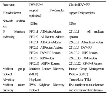
(3) local gateway router initially acts as a root and builds a new sourced-based multicast delivery tree [12]. The advantage is that it won’t need to provide encapsulation and decapsulation. Meanwhile, it also employs the Mobile IPv6 and DVMRP functionality without any modification. Furthermore, the routing of multicast can maintain its optimization. Nonetheless, there are disadvantages. First, the method of re-route will wastes since sender must rebuild a new source routed multicast delivery tree after each movement. Recreating a multicast tree will cause serious disruption in data reception. Thus, when sender changes its attached link, the system will have a long delay time.. 3. IPv6 Supporting DVMRP Our proposal implements DVMRP routing protocol in an IPv6 network for multicasting. We will call it DVMRPv6. There are many different features between DVMRPv6 and classical DVMRP depicted in Table 1. The following are their differences: IP header format: The IPv6 header format is simpler than IPv4. The result is that the IPv6 header will be streamlined and more efficient in operation. IP address size: An IP address changes from 32 bits to 128 bits. Consequently, the larger address size supports an enormous and heterogeneous IP-based environment. IP multicast addressing: IPv6 multicast addresses are reserved and assigned from the prefix 1111 1111 (0xFF). The IP Multicast addressing in Table 1 is part of the list of IPv6 and IPv4 multicast addresses reserved for IP multicasting and registered at the Internet Assigned Numbers Authority (IANA). Multicast group protocol: An IPv6 node who desires to receive multicast datagram on its attached links is discovered by Multicast Listener Discovery (MLD) protocol. Similar to IGMP, local group members are discovered by MLD protocol. A node may participate in a group member as a source or as a receiver. The key difference between MLD and IGMP is that MLD supports IPv6 instead of IPv4. Besides, MLD protocol represents a sub-protocol. . . to ICMPv6 and a subset of the set of ICMPv6 messages. Alive time: In classical DVMRP routing protocol, Time to Live (TTL) of the message must be set to 1. New IPv6 header uses Hop Limit instead of TTL. Multicast router discovery: In IPv4, Multicast router discovery uses IPv4 multicast router solicitation and advertisement mechanism. On contrary, IPv6 multicast router discovery uses new Neighbor Discovery (ND) protocol mechanism.. Table 1 The differences between DVMRPv6 and classical DVMRP Parameters. DVMRPv6. IPheader format Network address size IP. Multicast. addressing. Multicast. group. support. Classical DVMRP IPv6(simpler,. optimized). support IPv4(complex). 128 bits. 32 bits. FF01::1 All Nodes Address. 224.0.0.1. FF01::2 All Routers Address. systems. FF02::1 All Nodes Address. 224.0.0.2 All multicast routers. FF02::2 All Routers Address. 224.0.0.4 DVMRP. FF02::4 DVMRP Routers. 224.0.0.9 RIP2 Routers. FF02::9 RIP Routers. 224.0.0.13 PIM Routers. FF02::D All PIM Routers. 224.0.0.22 IGMPv3 Reports. Multicast Listener Discovery. Internet Group Management. All. multicast. protocol. (MLD). Protocol (IGMP). Alive time. Hop Limit. Time to Live (TTL). IPV6 Neighbor Discovery. IPv4 multicast router solicitation. Protocol. and advertisement mechanism. Multicast discovery. router. 4. Modification of Packet Formats How to handle sender movement on the Mobile IPv6 network is a serious and difficult problem for the multicasting. In this section, we modify some header format of protocols in order to solve this problem. 4.1 Modification of ND Protocol Format The Multicast Router Discovery function for Mobile IPv6 is achieved by using the Neighbor Discovery (ND) protocol. Specifically, Fig 1(i) shows the Router Advertisement message that contains two fields to support the discovery of multicast routers. The two fields are the D-bit and E-bit bits described in [5]. Other fields such as M-bit, O-bit and H-bit retain their definitions and functions as described in [12,15]. Fig 1(ii) shows the practical modification of Router Solicitation message by the addition of a single flag bit. The modified message format is explained as follows:.
(4) Reroot (R) flag 1-bit: When set true, the R-bit indicates that the mobile node is a sender and moves in the new visited link. Furthermore, the DVMRPv6 router receiving the message will act as a new root of delivery tree of multicast group instead of Sender’s previous gateway router. The default setting is false.. multicast datagrams, it first checks if the Group ID is in its forwarding group table. If so, it connects to upstream router with the incoming interface. Other interfaces of the group ID are swapped as the outgoing interface. The default setting is false. 0 1 2 3 01234567890123456789012345678901. 0 1 2 3 01234567890123456789012345678901 Type Cur Hop Limit. Code. Traffic Class C Payload Length. Checksum Router Lifetime. Rsvrd. MOH DE. Version. Flow Label Next Header. Hop Limit. Source Address. Reachable Time Retran Timer Options .... Destination Address. (i) New Router advertisement message format 0 1 2 3 01234567890123456789012345678901 Type. Code Reserved. R. Figure 3 New IPv6 Header Format. Checksum. Options .... (ii) New Router solicitation message format Figure 1 Multicast Router Discovery Message Format. 4.2 Modification of MLD Header Format Fig 2 shows the MLD header format that has been changed by the addition of one flag bit. This format represents the following change: Source (S) flag 1-bit: When set true, the S-bit indicates that sender’s new gateway router must forward multicast datagrams to all its interfaces of this group ID (GID) as well as update its forwarding group table. Generally, the flag is set with MLD Report message when a Sender visits a new foreign link .The default setting is false.. 4.4 Modification of Binding Update message The new Binding Update (BU) Message by the addition of single flag bit is depicted in Fig 4. The other fields of Binding Update (BU) message are specified in [12]. The modified message format is as followed: Backward-Forced (F) flag 1-bit: When set true, the F-bit indicates that Sender notifies its pervious gateway router to keep the integrity of the multicast delivery tree for a longer time. Furthermore, a reverse path from new gateway router (new root) to old gateway router (old root) will be built. The default setting is false.. 0 1 2 3 01234567890123456789012345678901 AH L K F. 0 1 2 3 01234567890123456789012345678901 Type Code Maximum Response Code. S. Checksum Reserved. Reserved. Sequence # Lifetime. Mobility options. Figure 4 New Binding Update message. Multicast Address. Figure 2 New MLD Header Format. 4.3 Modification of IPv6 Header Format The new IPv6 header format by the addition of single flag bit is depicted in Fig 3. The format represents the following changes over the flow label field: Checkage (C) flag 1-bit: When set true, the C-bit indicates that DVMRPv6 router will start a check in/out interface function. Upon receiving. 5. Reverse Traffic Interface (RTI) Mechanism In this paper, we propose a Reverse Traffic Interface (RTI) mechanism to handle sender movement problem. If a sender disconnects from its current link and moves to a new visited link, multicast datagram won’t be delivered anymore. We create a provisional forwarding group table and modify some header format of IPv6 protocols. Then it is imperative to check if there exists a backward path from new source node (new root) to previous source node (old root). If so, there is a backward path from.
(5) new root to old root that we called Backward-Forced Path (BFP). The mechanism guarantees multicast datagrams be sent to all receivers. Consider an example of delivery tree of multicast group on the DVMRPv6 topology network depicted in Fig 5. Assume a Sender moves to a new location, it sends a Router Solicitation messages to the All-Routers multicast address (FF02::2). It also sets the HopCount to 1 and R-bit to true (Enabled) in order to solicit DVMRPv6 router’s location. Multicast router R2 receives a Router Solicitation message by sender and the R-bit is true. The R-bit being true (Enabled) represents the new gateway router R2 will know that the mobile node is a mobile sender of a delivery tree of multicast group. Moreover, the multicast router R2 replies a solicited Router Advertisement message to the Router Solicitation multicast address as sender’s address. The message contains some Internet information (e.g. hop limit value, MTU, and subnet prefix information.). As a result, sender gets a Care-of-Address with stateless address autoconfiguration. Router MLD Report message Backward Forced Path Sender. LGR Local Gateway Router. R1. Sender. old root BFP. Sender. HA LGR. new root. R2. R1. R2. R3. R3. Receiver 1 R4. Receiver 1. R5. R4. R5. R6. R6. Receiver 2. Receiver 2 R9. R7. R9. R7. R8. R8. Receiver 3. Receiver 3 Receiver 4. (i). Receiver 5. Receiver 4. Receiver 5. (ii). Figure 5 An example of sender mobility with new gateway router as group members. As shown in Fig 5(i), sender sends Binding Update (BU) Message and sets F-bit to true to notify previous gateway router R1. It must keep the integrity of the delivery tree to avoid the full tree being pruned. Furthermore, new gateway router (new root) R2 keeps a reverse path back to old gateway router (old root) R1. The reserved path is called Backward-Forced Path (BFP). The BFP provides a short cut from new root to old root that prevents the destruction of the full structure of original delivery tree. It can make the multicast datagrams keep forwarding. The changed root regenerates a new delivery tree but no re-route is required. Generally, a gateway router of mobile nodes is viewed as a querier router on Mobile IPv6 network. Sender directly sends a MLD. Report message to the gateway router and sets S-bit to true. Here, there are three conditions which might happen in a gateway router of DVMRPv6 network. Firstly, the gateway router is a child router of delivery tree. Secondly, the gateway router is a leaf router of delivery tree. Lastly, the gateway router does not participate in the multicast group. The following explains the steps to be taken for each case. The first condition is that the new gateway router is a child router. Look at Fig 5(i), we can assume that R2 is a group member and the C-bit is true as well as the Group ID (GID) of this datagrams is in the R2’s forwarding group table (FGT). Upon receiving multicast datagram from sender, R2 will set an interface to connect with sender. The interface becomes a physical incoming interface. Other interfaces of this group are swapped and turned into the outgoing interface. Thereupon, R2 updates its forwarding group table. R2 receives datagrams from sender and forwards them to R1 and receiver 1. Since R1 is the original source router, it receives the datagrams from its previous downstream interface of tree. If the C-bit of header is true as well as the Group ID of this datagrams is in the R1’s group table, R1 sets this received interface to become a physical incoming interface of group. Other interfaces of this group are swapped as the outgoing interface, except for R1’s original incoming interface. R1 updates its group table and forwards datagrams to its sub-tree (i.e. children R3, R4, R6, R7, and R8). The final result is depicted in Fig 5(ii). Meanwhile, the tree structure has no obvious changes. The only difference is the root change and it has a reverse path from new root to old root. Algorithm 1 illustrates the Reverse Traffic Interface function. Algorithm 1: Reverse traffic interface function /* Upon receiving multicast datagram when Sender visits a foreign link */ if. C-bit is true if. then. The GID of this datagrams is in the DVMRPv6 router’s FGT then if. not The incoming interface of GID matches the incoming field of FGT then Another interface of this GID are swapped as the outgoing interface and. Update FGT. end if Forward multicast datagrams directly else Discard this datagrams end if end if.
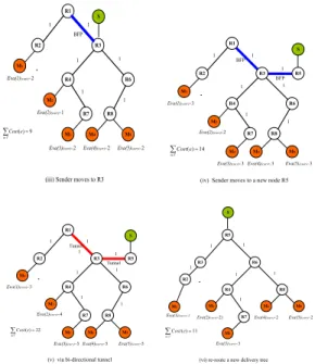
(6) The second condition is that the new gateway router is a leaf router. Assume the R2 of Fig 5(ii) is a leaf router. The Sender’s new gateway router R2 sends a Graft message to its upstream router R1. R2 Re-clipped the delivery tree, then the active procedure is the same with above-mentioned. For the third condition, Fig 6(i) is another example of delivery tree on the DVMRPv6 network topology. Sender moves to a new link and attaches to R5. R5 isn’t a group member. To start neighbor discovery function, R5 finds the latest router of group (e.g. multicast router R6) as well as continues to forward the multicast datagrams. Using the same above-mentioned procedure, it creates a path from new source router R5 to old source router R1. Sender floods multicast datagrams from R5 to all of group members. The final result is depicted in Fig 6(ii).. Router MLD Report message Backward Forced Path DVMRPv6 Probe message. Sender. old root. LGR Local Gateway Router. R1. R1. HA R2. BFP. R2 R3. BFP. R3. Sender. Receiver 1. Sender. Receiver 1 R4. R5. R4. LGR. R6. Receiver 2. R5. new root. R6. Receiver 2 R9. R7. R9. R7. R8. R8. Receiver 3. Receiver 3 Receiver 4. Receiver 5. sum of cost on all links in a path to be traveled. In our proposal, hop count specifies the number of internetworking routers in which a datagram must take en route from a source to a destination. Given a connected and directed network graph G= (V, E), V is a set of vertices as nodes, and E is a set of edges as links. In a delivery tree T (T ∈ G) rooted at s and spanning all of the nodes in V, a path from u to v is denoted by P(u, v), where u, v ∈ V. Let Cost(e) represent the cost of traveling edge e, e ∈ E. Define an evaluation value of a path as Eva= ∑Cost(e), Vs is a mobile sender, Vm is a mobile receiver. Eva is used to estimate the performances of routing. Given a mobile sender Vs and a set of mobiles receivers Vms, we omit the cost of air link between mobile node and gateway router. Therefore, the evaluation of cost consumption and path length will be terminated at the mobile node’s gateway router. If the sender is attached to the root of the original multicast tree, we label the evaluation value as Eva(i)(orgi) for router i. If the sender is attached to a visited router of the adjusted delivery tree, we label the evaluation value as Eva(i)(curr) for router i. We also define one measure to estimate the cost full adjusted tree. The total cost consumption of the tree is denoted by ∑Cost(e). Fig 7 shows an example of such an original multicast delivery tree that is applied to Fig 5(i). Assume that each hop consumes a unit of cost and neglect the cost of air link. Also assume that sender Vs is attached to a source router R1 (i.e. also its HA). Multicast datagrams spanned to all of receiving routers R2, R3, R4, R6, R7, and R8. It also has five receivers Vm1, Vm2, Vm3, Vm4, and Vm5 attached to their gateway routers R2, R4, R7 and R8 respectively. For Vm5, ∑Cost(e) = (1 + 1 + 1) = 3. That is, The evaluation value Eva(5)(orgi) is 3. The other receivers Vm1 to Vm4 is computed and labeled as Eva(1)(orgi) = 1, Eva(2)(orgi) = 2, Eva(3)(orgi)= 3, and Eva(4)(orgi) = 3. Hence, full delivery tree has total cost consumption = (1 + 2 + 3 + 3 + 3) = 12. e∈T. e∈T. Receiver 4. (i). Receiver 5. (ii). Figure 6 An example of sender mobility when the new gateway router is not a group member. 6 Evaluations and Simulations 6.1 Evaluations In this paper, we implement a multicast routing protocol with dynamic and adjusted root of delivery tree on Mobile IPv6 network. When sender moved, its newly attached gateway router will become the new root replacing the original one. In our scheme, the imperative issue is whether there is a Backward-Forced Path (BFP) between the new root and the old root. It can regenerate a new adjusted tree without re-routing. This method not only keeps the original structure of tree but also assures the multicast datagrams delivered as usual. In the past, the qualities of dynamic multicast routing have also been studied in Kompella el al. [13], Adelstein el al. [2], and [19]. In order to evaluate and compare the routing metrics between the original delivery tree and the new delivery tree, we select one common measure to estimate the quality of the new delivery tree. It is Cost Consumption, the. e∈T. S. R1 1. R1. S. 1. 1. R2. R3. R2. R3. 1. 1. M1. 1 BFP. Eva(1)(orig)=1. R4. R6. Eva(1)(curr)=0. R4. 1 Eva(2)(orig)=2. ∑ Cost (e) = 12 e∈T. R7 M3. Eva(3)(orig)=3 Eva(4)(orig)=3. (i) Original delivery tree. 1. M2. R8. M4. Eva(2)(curr)=3. M5 Eva(5)(orig)=3. R6 1. 1. M2. 1. 1. M1. ∑Cost(e) = 15 e∈T. R7 M3. Eva(3)(curr)=4. R8. M4 Eva(4)(curr)=4. (ii) Sender moves to R2. M5 Eva(5)(curr)=4.
(7) S 1 BFP R1. R3. S 1. 1. 1. BFP. R2. Eva(1)(curr)=2. R4. 1. R3. BFP 1. R6 1 1. Eva(2)(curr)=1. 1. M1. M2 R7. Eva(1)(curr)=3. R4. R6. R8. 1 1. M2. ∑Cost(e) = 9. M3. e∈T. M4. Eva(3)(curr)=2. R5. Eva(2)(curr)=2. M5. ∑ Cost( e) = 14. Eva(5)(curr)=2. Eva(4)(curr)=2. R7 M3. e∈T. R8. M4. M5. Eva(3)(curr)=3 Eva(4)(curr)=3. (iii) Sender moves to R3. Eva(5)(curr)=3. (iv) Sender moves to a new node R5. S. R1. R5. S 1. Tunnel 1. 1. R2 1. M1. 1. 1. R3. 1. R5. Tunnel 1. R3. 1. R6. Eva(1)(curr)=3. R4. R6. R4. 1 M2. ∑ Cost (e) = 22 e∈T. R7 M3. R8. M4. Eva(3)(curr)=5 Eva(4)(curr)=5. (v) via bi-directional tunnel. M5. M2. M1 Eva(1)(curr)=2. Eva(5)(curr)=5. R8 1. 1. Eva(2)(curr)=4. 1. 1. R2. R7. Eva(2)(curr)=2). ∑ Cost ( e) = 11 e∈T. M4 Eva(4)(curr)=2. M5 Eva(5)(curr)=2. M3 Eva(3)(curr)=3. (vi) re-route a new delivery tree. 6.2 Simulations We use the most popular simulation tool– ns2 [20,21] to experiment with our scheme on Red Hat Linux 7.2 system. Assume there are 30 intermediate routers, 20 border routers and 10 mobile nodes. We devise a random selection to choose a mobile node acting as a sender. The sender floods mass UDP datagrams to another. 1200. 250 total tree cost. 200 150 100 50. 1000 800 600 400 200 0. 0 1. 2. 3. 4. 1. 5. 2. 3. 4. 5. the number of times of sender moving. the number of times of sender moving. (i). (ii). Figure 8 The total cost of multicast tree with two multicast groups Proposed scheme Bi-directional tunnel Rebuilding tree. Proposed scheme Bi-directional tunnel Rebuilding tree. 500 total tree cost. We assume some different cases of changed root and adjusted tree to compare each receiver’s evaluation value and the total cost of full tree. Fig 7(ii), Fig 7(iii), and Fig 7(iv) are examples. Fig 7(v) and Fig 7(vi) are other cases. First of all, assume Sender moves and attaches to a child router, then the child router acts as a new root and regenerates an adjusted tree without re-routing. Fig 7(ii) and Fig 7(iii) are two examples. In Fig 7.1(ii), the bold line marks the BFP between R2 and R1. The full adjusted tree has the total cost of 15. In Fig 7(iii), the full adjusted tree has the total cost = 9. The total cost in Fig 7(ii) is greater than that of the original tree. The result means its efficiency is worse than that of Fig 7(i). On the contrary, the efficiency of Fig 7(iii) is better. Another case is when sender moves and attaches to a new root whose gateway router does not participate in the multicast group. The new root is a new participant. Using our method shown in Fig 7(iv), it has a total cost of 14. But if using the traditional bi-directional tunnel method shown in Fig 7(v), it has a cost of 22. Of course the best is a rerouted tree shown in Fig 7(vi), it has a cost of 11. However, it will incur a very long delay.. Proposed scheme Bi-directional tunnel Rebuilding tree. Proposed scheme Bi-directional tunnel Rebuilding tree. Figure 7 Dynamic adjusted root of delivery tree. sum of total tree cost. 1. M1. sum of total tree cost. R2. five random mobile nodes. We measure the cost of the adjusted tree and the average end-to-end delay. In the simulation, we calculate the cost of full adjusted tree and end-to-end delay each times when the sender moves. We compare our method with the bi-directional tunnel scheme and the rebuilding tree with re-routing scheme. Fig 8(i) (ii) shows the results of our experiment with two multicast groups. Fig 9(i) (ii) shows the results with four multicast groups. According to the results, the bi-directional tunnel scheme has the worst cost performance as can be expected. The rebuilding tree with re-routing scheme has the best cost performance. However, recreating a multicast tree will cause serious discontinuity in receiving the multicast datagram. Our proposed scheme can create a nearly optimal tree without rebuilding the tree.. 400 300 200 100 0 1. 2. 3. 4. 2500 2000 1500 1000 500 0. 5. 1. the number of times of sender moving. 2. 3. 4. 5. the number of times of sender moving. (i). (ii). Figure 9 The total cost of multicast tree with four multicast groups. In Fig 10, the comparison of average end-to-end delay is shown. This delay is collected only from the datagrams that have been successfully received by the receivers. Obviously, rebuilding tree scheme results in longer end-to-end delay compared to bi-directional tunnel scheme and our proposed scheme. The delay between tunnel scheme and our proposed scheme are close. Therefore, our proposed scheme improves the transmission cost without increasing the delay. average end-to-end delay(ms). R1 1. Proposed scheme Bi-directional tunnel Rebuilding tree 100 90 80 70 60 50 40 30 20 10 0 1. 2. 3. 4. 5. 6. 7. 8. 9. 10. the number of times of sender moving. Figure 10 The comparison of End-to-End delay.
(8) 7. Conclusions Mobile IPv6 supports multicasting. However, the movement of sender may cause a serious problem so that multicast datagrams can’t forward to all receivers. Therefore, we propose a Reverse Traffic Interface (RTI) mechanism to preserve the integrity of adjusted tree. In our scheme, we create a Backward-Forced Path (BFP) to regenerate a new tree without re-routing. It ensures multicast datagrams be sent to all reachable destinations without interruption. In addition, a slight modification of the DVMRP version 3 can be used to Mobile IPv6, which is called DVMRPv6. Subsequently, we use a total tree cost to estimate and judge our scheme and implement a simulation to manifest the effect. From the results of evaluation and simulation, our scheme can obtain good efficiency and reliability even if sender moved. The previous bi-directional tunnel method needs to consider HA and may cause the to and fro problem. Therefore, its cost performance and efficiency is the worst and their reliability is worse. Rebuilding tree is optimal, but it has a long delay time which leads to other problems. Our proposed scheme can create a nearly optimal tree without rerouting. It has less cost consumption than the bi-directional tunnel scheme. As a result, our proposal makes multicasting on mobile networks more efficient and reliable. Our goals for future work include experimenting on a mobile network of 3G or beyond 3G and evaluating the performance when applied to actual multicast networks. We are also considering the coexistence of many multicast sessions and to find more suitable ways to handle the problem of sender movement.. References [1] Adams, A., Nicholas, J., Siadak, W., “Protocol Independent Multicast – Dense Mode (PIM-DM): Protocol Specification (Revised)”, Internet Draft <draft-Internet-pim-dm-new-v2-02.txt>, February 2003. [2] Adelstein, F., Richard III, G.G., and Schwiebert, L., "Building Dynamic Multicast Trees in Mobile Networks, "1999 ICPP Workshop on Group Communication, pages 17-22, September, 1999. [3] Ballardie, A., “Core Based Trees (CBT version 2) Multicast Routing–Protocol Specification”, RFC 2189, September 1997.. [4] Ballardie, A., “Core Based Trees (CBT) Multicast Routing Architecture”, RFC 2201, September 1997. [5] Biswas, S., Cain, B., Haberman, B., “Multicast Router Discovery”, Internet Draft “draft-ietf-idmr-igmp-mrdisc-10.txt”, January 2003. [6] Droms (ed.), R., Bound, J., Bernie Volz, Ted Lemon, Perkins, C., Carney, M., “Dynamic Host Configuration Protocol for IPv6 (DHCPv6)”, Internet Draft <draft-Internetdhc-dhcpv6-28.txt>, November 2002. [7] Deering, S., Fenner, W., “Multicast Listener Discovery (MLD) for IPv6”, Internet Draft <draft-Internet-ipngwg-mld-02.txt>, June 1999. [8] Deering, S., Fenner, W., Haberman, B., “Multicast Listener Discovery (MLD) for IPv6”, RFC 2710, October 1999. [9] Deering, S., Hinden, R., “Internet Protocol, Version 6 (IPv6) Specification”, RFC 2460, December 1998. [10] Estrin, D., Farinacci, D., Helmy, A., Thaler, D., Deering, S., Handley, M., Jacobson, V., Liu, C., Sharma, P., Wei, L., “Protocol Independent Multicast -Sparse Mode (PIM-SM): Protocol Specification”, RFC 2362, June 1998. [11] Hinden, R., Deering, S., “IP Version 6 Addressing Architecture”, RFC 2373, July 1998. [12] Johnson, D., Perkins, C., Arkko, J., “Mobility Support in IPv6”, Internet Draft <draft-Internet-mobileip-ipv6-21.txt>, February 26, 2003. [13] Kompella, V. P., et al, “Multicast Routing for Multimedia Communication”, IEEE/ACM Trans. on networking, 1(3), pp.286-292, 1993. [14] Moy, J., “Multicast Extensions to OSPF”, RFC 1584, March 1994. [15] Narten, T., Nordmark, E., Simpson, W., “Neighbor Discovery for IP Version 6 (IPv6)”, RFC 2461, December 1998. [16] Perkins, C., “IP Mobility Support for IPv4”, RFC 3344, August 2002. [17] Pusateri, T., “Distance Vector Multicast Routing Protocol”, Internet Draft <draft-Internet-idmr-dvmrp-v3-10>, August 2000. [18] Waitzman, D., Partridge, C., Deering, S.E., “Distance Vector Multicast Routing Protocol”, RFC 1075, Nov-01-1988. [19]http://www.csee.usf.edu/~christen/ lcn99_2.pdf [20] http://www.inrialpes.fr/planete/mobiwan/ [21] http://www.isi.edu/nsnam/ns/.
(9)
數據


+2
相關文件
You are given the wavelength and total energy of a light pulse and asked to find the number of photons it
Then, it is easy to see that there are 9 problems for which the iterative numbers of the algorithm using ψ α,θ,p in the case of θ = 1 and p = 3 are less than the one of the
We explicitly saw the dimensional reason for the occurrence of the magnetic catalysis on the basis of the scaling argument. However, the precise form of gap depends
incapable to extract any quantities from QCD, nor to tackle the most interesting physics, namely, the spontaneously chiral symmetry breaking and the color confinement..
Miroslav Fiedler, Praha, Algebraic connectivity of graphs, Czechoslovak Mathematical Journal 23 (98) 1973,
Shih, “On Demand QoS Multicast Routing Protocol for Mobile Ad Hoc Networks”, Special Session on Graph Theory and Applications, The 9th International Conference on Computer Science
Acceptance of donations for naming rights (i.e. donations made on the condition that the receiving organization will name a specified “asset”, such as a building, a school,
Establish the start node of the state graph as the root of the search tree and record its heuristic value.. while (the goal node has not
