2006 IEEEInternational Conferenceon Systems, Man, and Cybernetics
October8-11, 2006, Taipei, Taiwan
Behavior Fusion
of
Robot
Navigation
Using a Fuzzy Neural Network
Kai-Tai Song and Jean-Yuan Lin Abstract-This paper presents a design of
behavior-fusion architecture for mobile robot navigation. We first design three behaviors for robot navigation, including obstacle avoidance, wall following, and goal seeking. We implement these primitive behaviors by using fuzzy-logic control approaches. Then, the fusion weight of each behavior is determined by using the proposed behavior-fusion neural network. The neural network maps the currentenvironment sensor data to suitablefusionweights. Both computer simulation and practical experiments verifytheeffectiveness ofthemethod.
I. INTRODUCTION
Behavior-based architectures have been widely used for navigation control of mobile robots[l-2], because these architectures facilitate a mobile robot to react inreal timeto the environmental information. With behavior-based approaches, one decomposes complex navigation tasks into several, well-specifiedbehaviors that are easierto designand carry out. In [2], robotic behavior is defined such that a
behavior is a control law that satisfies a set of constraints to
achieve and maintainaparticulargoal. Thus whenabehavior is activated, the output of the behavior never takes into account of other behaviors, each behavior is designed to
achieve a specified navigation task. However, it also means
that there may have conflicts among the outputs of different behaviors.For morepracticalapplications,the environmentas
wellasthetask will becomemore complex.The coordination of behavior sets becomes important. Many behavior coordination and fusion methods have been studied inrecent
years[3-7]. Basically, behavior coordination can be
categorizedinto twogroups, namelybehavior arbitration and behavior fusion. In the former, only one behavior's output will be validat anyone timeaccordingthe sensory inputs [1]. While for thelatter,eachbehaviorcanhave the
opportunity
tocontribute the control output, depending on the sensory information. Theproblemof behavior fusionthenbecomesto
determine theparticipation weightof each individual behavior. Thispaperstudies afuzzy-neuro designfordeterminingthe fusionweights ofseveralnavigationbehaviors. Inthisdesign,
a mapping between fusion weights and the immediate environmental configuration is generated for providing the proper fusion weights efficiently. The purpose is to achieve autonomous navigation in adynamic changing environment. We first designed three
primitive
behaviors for autonomousnavigationinanindoor environment. These behaviors are This work was supported by the National Science Council of Taiwan
goal seeking behavior, wall following behavior, and obstacle avoidance behavior. Each behavior is designed by using simple fuzzy logic control approach to achieve respective navigation task. The output of fuzzy logic controller of each behavior reacts to environmental information from ultrasonic sensorsand the motor shaft encoder signals.
II. FUZZYBEHAVIORS
Amobile robot equipped with ultrasonic sensors has been designed and constructedas shown in Fig. 1. The mobile robot has twoindependent drive wheels and two casters for balance. Robotmotion is controlled by adjusting the velocities of two driving wheels. The velocity servo control is handled by a self-made two-axis motion control card based on a TMS320F240 DSP chip. The ultrasonic sensors can measure distance up to five meters with 4Hz for one scanning of all twelve sensors onboard. In this study, we use only the front nine sensors for navigation design. The output of the fuzzy logic controller, which implements each behavior, is designed to change the moving direction of the mobile robot. We suppose that the mobile robotmovesforward with a constant linear speed. If the output of fuzzy logic controller, i.e. the speed difference oftwo drive wheels, ofa behavior is zero, the mobile robot willthenmovestraight forward.
Fuzzy systems have the capacity to handle uncertain and imprecise information using linguistic rules. When a mobile robot navigates in an unstructured environment, it needs to detect itssurrounding environment and interprets the gathered environmental information. From sensory information, the robot can obtain the knowledge of its position and the distance to surrounding obstacles. Fuzzy logic control (FLC) have been widely used for mobile robot navigation [8-12], mainly due to FLC is capable of offering inference using environmental data, even under motion and sensor uncertainties. We designedthreeprimitive behaviors by using FLC. The inputs of each FLC are distances measured by ultrasonic sensors, and the output is the differential speed between left and right drive wheels (cm/s). We divided nine front-side sonar sensors intofivegroupstodetect the distance from surrounding obstacles as shown in Fig.2. Ineach group the minimum sensor value is taken as the distance from
obstacles in five directions as shown in Fig. 3. In the following,these threebehaviorsaredescribed.
A. Obstacle Avoidance Behavior
We used three fuzzy rules to implement the obstacle avoidancebehavior.Theyarelistedasfollows.
c.Ifthe distance from obstacle is far, then the differential speed is small.
Fig. 1. The experimentalmobile robotequippedwitharing of twelve ultrasonic sensors.
Fig. 4 shows the fuzzy logic design of obstacle avoidance behavior. The front side sensors S3-S5 (Group 2) are used in this behavior as input to the FLC. Furthermore, we use the distance information from ultrasonic sensor 2 and ultrasonic sensor 6 (see Fig. 5)to decide which side that robot should chooseto avoid the obstacle, which is infront of the moving direction of the robot. The membership functions of input and output fuzzy variables are illustrated in Fig. 6. One can see that by using only three fuzzy rules, the differential speed between left andright wheels can bedetermined for obstacle avoidance. The overall input-output relation of obstacle avoidance behavior is shown inFig.7.
FuyController
-I._I __e
Fig. 4. Fuzzylogicdesign of obstacle avoidance behavior Group-2 Group- t St Groop -o so Group-3 Group-4 ar7 Sonar 2 Sonar 6 Sonar3-4-5 = >--::*ff0f0X0m:0000::; II7X fi0;S s5o
Fig. 2. Numbering of theultrasonic sensors.
SoBar4
V-dif
Fig.5. Inputand outputof the obstacle avoidance behavior.
Input membership Sonar5 Sonar6 Sons 50 100 150 200 Sonar input(cm) Output membesp
, i small medium big
1'.
Sonar8
Fig. 3.Groupingof theultrasonicsensors onthe
mobilerobot.
Differentialspeed oftwo
t,1VA-.1Q(o lQW
0 10 20
Vdif
Fig. 6. Themembershipfunction of obstacleavoidance FLC.
Sonar3 SoBar2 A Sonar1 Sonar0 I )
anvewneeism/s)
IFig. 7. Input /outputrelation ofobstacle avoidanceFLC. B. Goal SeekingBehavior
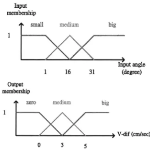
In this design, the behavior ofgoal seeking is treated as trying to move along the direction to the target. Using the definition, we define the relative angle between the robot heading and goal direction as the input of the goal seeking FLCbehavior.Asillustrated inFig. 8, the relative angletothe goal is used to determine the differential speed of mobile robotby usingfuzzy inference. The fuzzy rulesare asfollows.
a. Iftheincludedangleisbig, then the differentialspeed is big. b. Iftheincludedangle ismedium,
then the differentialspeed is medium. C. Ifthe includedangleis small,
then the differentialspeed iszero.
The rules areused to modulate theheading of mobilerobot. Let the robot move along the direction to the target. Its membership function of rules is displayed in the Fig. 9. The inputand output relation of thegoal seekingFLC is shown in Fig. 10. One can see that when the angle to the target direction increases, the differential speed betweentwo driver wheelsincreases, too.
Goal
~~~~Robot
headinginputinputanglengle0 0 Robotheading
Input membership smal big 1 16 31 Output membership
zeroz mediam big
1
0 3 5
Fig. 9. Membership function of the goal seeking FLC.
~4 3 5tO16 20 25 3 35 400 :; 04 jr --X;V:-:;--~3 ::~~~~~~ ~~~W mn u .... ... iS~~~~~~~~~~~~~~~~~~~~~~~~~~~~~~~~~~~~~~~~~~~~...:
Fig.
10.Input/output
relation ofgoal
seeking
FLC.C. Wall
Following
BehaviorThe wall
following
behavior is definedas tokeep
thesamedistance with the nearestwall.
Fig.
11Idepicts
thedesign
of wall following behavior. We calculated the difference of left andright
distance obtained from thecorresponding
sensors.The distance difference inthe left and
right
direction in twosamples
is takenastheinput
tothefuzzy logic
controller. The output offuzzy logic
controller is the differentialspeed
betweentwo drive wheels. The
membership
function of wallfollowing
behavior is shown inFig.
12.Following
this definition, wedesigned
threefuzzy
rules to achieve the wallfollowing
behavior.a. Ifthe differentialdistanceis
big,
then the differentialspeed
isbig.
b.lfthedifferential distanceismedium, thenthedifferential
speed
ismedium.C. Ifthe differential distance is
small,.
then the differentialspeed
iszero.When the differential distance is
bigger,
thedifferentialspeed
should belarger.
Theinput
and output relation ofthe wallfollowing
FLCis shown inFig.
13.Fig.11.Design of wall-following behavior.
Input membiip
small medium big
1 ' -IV 0 10 20 Difference in sonarinputs
Output
Output membershipizero medium big
1V)
V-dif(cm/s)
0 5 10
Fig. 12. Membership function of wallfollowingFLC.
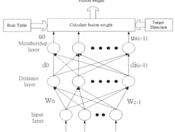
environmentpattern isnot similar with the prototype pattern, the degree of difference becomes larger. In the third layer of FKCN, we obtain the membership or degree ofsimilarity to the prototype pattern, from which the current fusion weights are determined. The Prototype patterns define the basic situation of environment as shown in Fig.15. In this design, eight prototype patterns are selected to represent typical situations for indoornavigation. Table.1 shows the behavior fusion weightcorrespondingto each prototype pattern. Inthe designphase, one needstoassign the default fusion weight in theFKCNfor distance calculation. Inapplication,astherobot obtains current sensordata,the FKCN canfindoutthe fusion weight corresponding to the immediate environment. FKCN has the capacity to generalize these prototype patterns to all situations that mayhappentothe robotdurationnavigation by giving the proper fusion weights. Fig. 16 illustrates the structureofbehavior fusion.
Notethat the ultrasonic distance dataare quantized to five levelsbeforesent totheFKCN.
Fusion weight
Rule Table Calculate fusionweight Target
layMer
(\) ) Vdi(c-i)
.1 :5 20 25 ...if :::
Fig.13.Input/output relation of wallfollowingFLC. IIl. FUZZY-NEUROBEHABIORFUSlON
The concept of pattern recognition was adopted for behavior fusiondesign. Itisutilizedtomaptheenvironmental pattern,obtained from ultrasonicsensorsonboard therobot, to
the fusion weight of threenavigation behaviors. Considering that "when the environment information of surroundings is similar, the fusionweightofnavigation behaviors should be similartoo," we usethe Fuzzy KohonenClustering Network (FKCN) [13-14] to recognize the environment. Fig.14 illustrates the structure of the fuzzy-neuro network for behaviorfusion.Inthefirstlayer of he network, thequantized value of distance is regarded as the inputs of FKCN. In the second layer, we calculate the degree of difference between the current and the prototype pattern. If the input current
W-i
Fig. 14. TheFKCNfor fusionweights determination.
1
4- 4 I P I,A) (E:H') ,NS..S..4;1,4
:1 1..4.,,..\\
A!Fig.15. Theprototype patterns.
4 .j
4 4
4 X. I
Table.1 Prototype patterns and fusion weights
hIIIIIIIZ 1122 VTHEN-Prt(Qethaviorfoisioinweiglht)
IF-Palt dinl dir 2 dir-3 dir=4 dii=5
prototypepattem W9 AV. NV.iw W. IV. W0 W. IV. Wv IV. W.v XVg XiV. W.
4 4 4 4 4 1 0 0 1 0 0 1 0 0 1 0 0 1 0 0 4 4 4 4 1 1 0 0 1 0 0 1 0 0 0.7 0.3 0 0.5 0.5 0 1 4 4 4 4 0.5 0.5 0 0. 0.3 0 1 0 0 1 0 0 1 0 0 4 4 1 1 1 0.2 0.8 0 IA 0.6 0 0 0.7 03 0 0.5 0.5 0.5 0.5 0 1 i1 1 4 4 0.5 0.5 0 0.5 0.5 0 0 0.7 03 0.4 0.6 0 0.2 0.0 0 4 4 1 4 4 0.4 0.6 0 0.2 0.0 0 0 1 0 0.2 0.0 O 0.4 0.6 0 1 2 4 4 4 0.4 0.6 0 0.5 0.5 0 0 0 1 0.3 0 0.7 0.7 0 0.3 4 4 4 2 1 0.7 0 0.3 0.3 0 0' 0a 0 O1 0.50.50 O0.4 0.6 0
dir = 3
1for
90<0<180 2for
30<0<90
for
-30<0<30
4for
30<0<
-905
for
-90<0<-180
Goalseeking VLandVR
following
Fig. 16. Block diagramof behavior fusion.
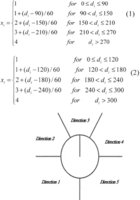
Forultrasonic sensorgroup 0,1,3,4,formula(1)is used for
quantization; where di is the measured distance in cmof the
ith sensor group (direction). For the sensor group (2),
formula(2)is used. The relativeangletothegoal positionalso
needs to be considered in navigation. The quantization of
relative angle to the goal position is shown in Fig.17. We divide the angletothegoalinto five sections. InFormula(3),
five directions are assigned. Theparameter dir represents the
direction section. |l+(di -x, = 2+(di 3+(di -4 -90)/60 -150)/60 -210)/60 I+(d,-120)/60 xi= 2+(d( -180)/60 3+(di-240)/60 4 Dirxtiw2 LWmt1 for O.<d <90 for 90<d_ <150 (1) for
150<di
<210 for 210<di<270 fordi
>270 for0<di
<120 for 120<d<'180 (2) for 180<di
<240 for 240<d, <300 fordi
>300IV. EXPERIMENTAL RESULTS
In this section, we present the experimental results of the proposed behavior fusion method. Fig. 18 illustrates the control structure of the mobile robot. Fig. 19 shows the experimental result of autonomous navigation in the lab environment. The robot navigated in a crowded room and
passed a narrow door before it entered a corridor. There are
several obstacles inthecorridorasdepictedinthefigure.This
experiment validates that the proposed behavior fusion is sufficient for the navigation in an indoor environment. In
Fig.20, the recorded behavior fusion weights of three behaviors are illustrated. One can see that the weight of
obstacle avoidance increasedat sampleinstants 150, 190, and 230. It reflects that the mobile robot detected obstacles indicated as square shape in Fig. 19. At sample instants 90
and 170, the fusion weights of goal seeking increased. It
means that at these sample instants, the robot did not detect
anyobstacle in itsheading direction, and it triedtoregulate its traveling direction towards the goal. The second experiment tested the robot when it meets a dead end. The navigation
result is shown in the Fig.21. One can see that the robot
escaped from the dead end and traveled in the corridor as
expected.
Fig.18. Thestructureofnavigationsystem.
Diextm4
Dhvaim5
Fig. 17.Assignment ofgoaldirections. Fig.19.Experimentresults ofnavigation througha narrow
door andinthe corridor.
Fig.20. RecordedfusionweightsofexperimentofFig. 19.
LK
/.. ; 00 h l u.. . SE
l.
Fig.21. Experimentresults ofescapingfrom a
dead-end.
V. CONCLUSION
This paper presents a behavior-fusion architecture for a
mobile robot. This architecture successfully coordinates the outputof threenavigationbehaviorsby usingthefuzzy-neuro
pattern recognition network. Thanks to the autonomous
behavior fusion design, the individual behavior can be
implemented using simple fuzzy logicrules. Theexperimental results reveal the system can determine the proper fusion
weight and response to the dynamic changing environment efficiently. However, it has been observed in theexperiments that there are some errors at the end ofpath. This is mainly
causedbythepositionestimationerrorof themobilerobot. In
the future, we will add more accurate localization design to
the robot and continue to investigate the behavior fusion
method formore complextasks.
REFERENCES
[1] R. A. Brooks. "A robust layered control system for a
mobile robot," IEEE Journal of Robotics and Automation, vol.2,no.7,pp.14-23, 1986.
[2] M.J.Mataric, "Behavior-basedcontrol:examples from navigation, learning and group behavior," Journal of Experimental Theoretical Artificial Intelligence, Special
Issue. SoftwareArchitecturePhys. Agents, vol. 9, pp.46-54., 1997.
[3] S. G. Goodridge and R. C. Luo, "Fuzzy behavior fusion for reactive control of an autonomous mobile
robot:
MARGE,"
Proc. of 1994 IEEE International Conference on Robotics and Automation, 1994, pp.1622 -1627.
[4] Wei Li and Xun Feng, "Behavior fusion for robot navigationinuncertainenvironments using fuzzy logic," Proc. of 1994 IEEE International Conference on
Systems, Man,andCybernetics, 1994, pp.1790-1796. [5] C. Ye and N.H.C. Yung, "Vehicle navigation strategy
based on behavior fusion," Proc. of 1997 IEEE
International Conference on Systems, Man, and
Cybernetics, 1997,pp.3698 -3703.
[6] N.H.C. Yung and C. Ye, "Avoidance of moving obstacles through behavior fusion and motion prediction," 1998 IEEE International Conference on
Systems, Man, andCybernetics,pp.3424-3429, 1998.
[7]
Cang Ye and Danwei Wang, "Anovel behavior fusion method for the navigation ofmobile robots," Proc. of 2000IEEEInternational Conference on Systems, Man,andCybernetics, 2000, pp.3526-3531.
[8] P. Rusu, E. M. Petriu, T. E. Whalen, and A. Cornell, and H. J.W. Spoelder, "Behavior-based neuro-fuzzy controller for mobile robot navigation," IEEE Transactions onInstrumentation andMeasurement, Vol.
52, Issue4,pp.1335-1340, 2003.
[9] Simon X. Yang, Hao Li and Max Meng. "Fuzzy control of a behavior-based mobile robot," The 12th
IEEEInternationalConference onFuzzySystems, 2003,
pp.319-324.
[10] X. Yang, M. Moallem, and R.V. Patel, "An improved fuzzy logicbasednavigation systemfor mobile robots," Proceedings ofthe 2003IEEE/RSJIntl. Conferenceon
IntelligentRobots andSystems, Las Vegas, USA, 2003, pp.1709-1714.
[11] Simon X Yang, Hao Li, and Peter X. Liu, "An embedded fuzzycontroller for abehavior-based mobile
robotwith guaranteedperformance,"IEEETransactions
onfuzzysystems,vol. 12, no.4,pp.436-446,2004
[12] S. Khatoon, "Behavior coordination of autonomous
mobile robot navigation by neuro-fuzzy system," Proceedings of the IEEE 31st Annual Northeast BioengineeringConference, 2005,pp.58-62.
[13] T . Huntsberger and P. Ajjimarangsee, "Parallel
Self-organizing Feature Maps for Unsupervised Pattern Recognition," Int'l. J. General Systems, vol. 16, no.4, pp.357-372, 1990.
[14] K.T. Song and L.H. Sheen, "Heuristic Fuzzy-neuro Network and itsApplicationtoReactiveNavigation ofa
MobileRobot," FuzzySets and Systems, Vol.110,No.3,
pp.331-340,2000. 1.2 0.8 0.6 0.4 0.2 0 1 21 41 61 81 101 121 141 161 181 201 221 241