The Efficacy of Coconut Fibers on the Sound-Absorbing and Thermal-Insulating Nonwoven Composite Board
Chen-Hung Huang1*, Jia-Horng Lin2,3
1Department of Aerospace and Systems Engineering, Collage of Engineering,
Feng Chia University, Taichung 40724, Taiwan
2Laboratory of fiber application and manufacturing, Department of Fiber and Composite Materials, Collage of Engineering, Feng Chia University, Taichung 40724, Taiwan
3School of Chinese Medicine, China Medical University, Taichung 40402, Taiwan
ABSTRACT
The aim of this study is to examine the efficacy of the coconut fiber on the sound absorption and thermal insulation performance towards the composite nonwoven fabrics. The 2D polyester fiber and 12D fire retardant three-dimensional hollow crimp polyester fiber are individually mixed with 4D low-melting point polyester fiber (4DLMf) to produce 2D polyester nonwoven fabric (2D-PETF) and 12D polyester nonwoven fabric (12D-PETF) respectively. Subsequently, the coconut fiber (CF) is then laminated with the 2D-PETF and 12D-PETF to fabricate two types of PET/CF composite boards through the multiple needle-punching techniques. Accordingly, the sound absorption, thermal insulation, Limiting Oxygen Index and relative mechanical properties of the PET/CF composite boards are evaluated properly. The experimental results reveal that both types of PET/CF composite boards possess excellent thermal insulation performance and fire resistance property. Also, for both types of PET/CF composite boards, the average sound absorption coefficient increases with the increased amount of CF.
Keywords: Sound absorption, thermal insulation, fire resistance, coconut fiber, polyester fiber, needle-punching method.
Introduction
The excessive noise is harmful to human health. It is more likely to affect people physically and psychologically such as tiredness, dulling of the senses, lack of concentration, and reduction in work efficiency, etc [1]. Therefore,
many countries have established noise abatement regulations to reduce the effects of noise pollution. Since then, the researchers have paid much attention to the issue of noise suppression. Noise is the longitudinal sound wave that transmits through the air. The sound insulation and sound absorption are the two primary noise control techniques to suppress the acoustic noise. With the high density and nonporous structure, the sound insulating materials are viewed as sound barriers to block the noise transmission. On the contrary, the most common sound absorbing materials are light weight and porous in nature. The abundant interconnected pores extending to the outer surface of sound-absorbing materials can allow air to pass through freely. While traveling through the sound-absorbing materials, the branched structures of porous sound-absorbing materials increase the resistance of air vibration and the friction between the air molecules and internal passage wall. Consequently, the sound absorption resulted from transforming sound energy into heat dissipation is achieved to reduce noise [2]. In the research work of Watanabe et al, a polyester fiber sound absorbing material with excellent sound absorbing capacity has been developed [3]. In general, the fiber-based sound absorbing materials are known for poor sound absorbing performance in low and medium frequency range. Parkinsona et al. stated that additional layer of impermeable membrane significantly increases the sound absorption performance of porous material in the low and medium frequency range [4]. Lin et al have focused on nonwoven fabric sound absorbing materials that consist of reasonable sound absorbing, thermal insulating and fire resistant capability [5-9].
Based on the environmental protection and conservation of natural resources, the use of recycled materials from products or industrial wastes has become a future trend in manufacturing industry [10-11]. The coconut fiber, one of the abundant agricultural wastes, possesses low density, high abrasion resistance, good acoustic resistance and low thermal conductivity, etc [12]. In addition to the cultivation of plants, the potential use of coconut fiber can also be used as the interior components in the automotive industry [13]. Recently, the sound absorption performance of coconut fiber has been extensively studied in the research community [14-15].
In addition to noise protection, the energy saving has become a newly emerging research field. The high energy-efficient design plays a key role in the construction of green building. Besides lighting system and home appliances, the heating and air-conditioning systems consume considerable amount of energy [16-17]. The building material with great thermal insulation capacity provides an alternative to maintain the temperature gradient. The reduction of heat flow can then decline the heating and cooling energy consumption. The reason that the thermal conductivity of static air coefficient is around 0.024 W/mK in room temperature makes the static air an excellent thermal insulating medium. Hence, the static air in the porous structure leads to effective thermal insulation for the fibrous materials. However, most of fibrous materials are flammable. Once the flammable fibrous materials are ignited, the rapid spread of fire causes serious damage to human life and property. Statistics also reveal that the fire accidents associated with fibrous materials are more likely to be severe and fatal. Therefore, the flame-retardant ability has
become a significant safety aspect in the development of fibrous materials in building industries. The Limiting Oxygen Index (LOI) is employed to measure the flame-retardant performance [18]. Based on the value of LOI, materials can be classified as flammable (LOI<20 %), slow-burning (LOI: 20 %~26 %), self-extinguishing (LOI: 26 %~34 %), and intrinsically non-flammable (LOI>35 %).
In this study, the coconut fiber is adopted as one of the constituent of porous sound absorbing material. Besides, the polyester fiber has been utilized as the base material for the fabrication of nonwoven composite boards. The coconut fiber (CF), together with polyester fiber, is used to fabricate the nonwoven composite board through the multiple needle-punching and thermal bonding techniques. The influence of coconut fibers on the sound absorption, thermal insulation and fire resistance performance of nonwoven composite board are properly conducted and evaluated by changing the added amount of CF. In addition, other relative physical properties such as maximum breaking strength, air permeability are also evaluated. The developed nonwoven composite board is intended to serve as an alternative for the home building material with cost reduction and environment benefits.
Experimental
Composite Board Preparation PET nonwoven fabric preparation
In this study, two types of PET nonwoven fabric are produced as the base fabric to make the multi-layer boards. Each of the 2D polyester fiber (length: 51 mm, manufactured by Far Eastern New Century Corporation, Taiwan) and 12D polyester fiber (length: 66.3 mm, manufactured by Far Eastern New Century Corporation, Taiwan) is individually mixed with 4D low-melting point polyester fiber (4DLMf, length: 51 mm, manufactured by Huvis Corporation, South Korea) to fabricate 2D polyester nonwoven fabric (2D-PETF) and 12D polyester nonwoven fabric (12D-PETF) by opening, blending, carding, lapping, and needle-punching (200 needles/min). During the nonwoven process, the amount of 4DLMf is chosen as 30 wt% in each type of PET nonwoven fabric according to our previous experimental results [19]. Each type of PET nonwoven fabrics weighs 200±10 g/m2. The microscope photograph of 2D polyester fiber, 4D low-melting point polyester fiber and 12D polyester fiber is shown in Figure 1 at 4X magnification. With higher denier, 12D polyester fiber is coarser and denser than 2D polyester fiber. Under the circumstance, the 2D-PETF contains more fibers than that of the 12D-2D-PETF at the same weight.
Figure 1. The microscope photograph of 2D polyester fiber, 4D low-melting point polyester fiber and 12D polyester fiber at 4X magnification.
PET board preparation
2D polyester fiber 4D low-melting point polyester fiber
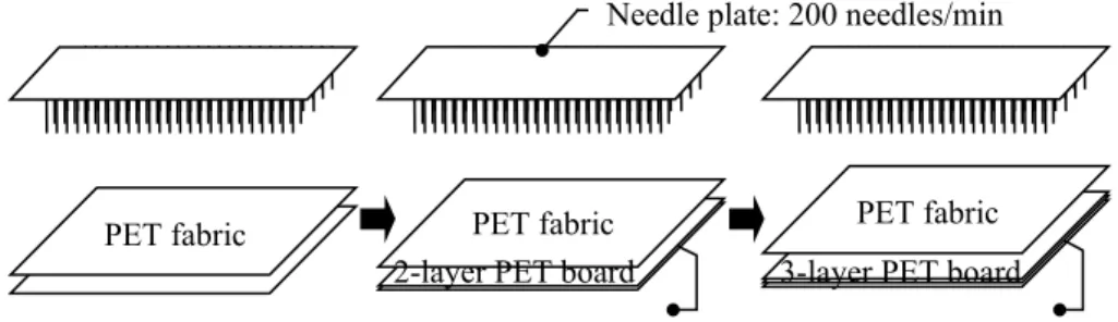
The 2D-PETF and PETF are used to fabricate the 2D-PET and 12D-PET boards respectively through the multiple needle-punching and thermal bonding techniques. In the lamination process, the multiple needle-punching technique is employed to make a multi-layer board with desired number of laminated layer. The number of laminated layers is chosen as 7, 8, 9, and 10 for both the 2D-PET and 12D-PET boards. When an additional PET nonwoven fabric layer is added each time, the needle-punching process takes place at 200 needles/min. The needle-punching process is schematically illustrated in Figure 2. After the lamination process, the boards casted into a mold (thickness of mold: 10mm) are then reinforced by thermal bonding technique in the hot air circulation oven at 130℃ for 10 minutes. Here, each type of PET boards with 10 base PET nonwoven fabric layers have served as the control group for demonstrating the efficacy of CF on the nonwoven composite board. The schematic diagram of 10-layer PET board is illustrated in Figure 3. The thermal bonding behavior between polyester fiber and 4D low-melting point polyester fiber is demonstrated in Figure 4.
Figure 2. The schematic diagram of needle-punching process for PET board.
PET fabric PET fabric
PET fabric
3-layer PET board 2-layer PET board
Needle plate: 200 needles/min
PET fabric layer
Figure 3. The schematic diagram of 10-layer PET board
Figure 4. Thermal bonding behavior between polyester fiber and 4D low-melting point polyester fiber
PET/CF composite board preparation
The 2D-PETF, 2D-PETF and coconut fiber (CF, average length: 12.9 mm) are used to fabricate two types of PET/CF composite boards through the aforementioned manufacturing process. Figure 5 shows the microscope photograph of 12D polyester fiber and coconut fiber at 4X magnification.
Figure 5. The microscope photograph of 12D polyester fiber and coconut fiber at 4X magnification.
The 2D-PET/CF composite board consists of 10 2D-PETF layers and 3 CF layers. In the process of lamination, one CF layer is placed between two 2D-PETF layers from the 4th to 7th 2D-PETF layers in the 2D-PET/CF composite
4D low-melting point polyester fiber
12D polyester fiber Thermal bonding spot
12D polyester fiber
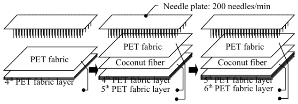
board. The needle-punching process takes place at 200 needles/min when an additional 2D-PETF layer is added each time. When the needle-punched composite fabric reaches the 4th layer, the coconut fibers are evenly dispersed on top of it as the CF layer. The needle-punching process takes place when another one 2D-PETF layer is placed on top of the CF layer. This process is duplicated and ended at the 7th 2D-PETF layer. In other words, the needle-punching process goes back to its initial setup from 8th to 10th 2D-PETF layer. Figure 6 illustrates the schematic diagram of needle-punching process for PET/CF composite board.
Figure 6. The schematic diagram of needle-punching process for PET/CF composite board.
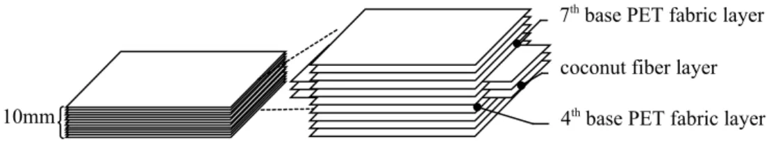
The same laminated structure is adopted to fabricate the 12D-PET/CF composite board. For each CF layer, the amount of CF is varied as 10 wt%, and 15wt% and 25 wt% based on the weight of one single PET nonwoven fabric layer (i.e. 200±10 g/m2) in both 2D-PET/CF and 12D-PET/CF composite boards. The schematic diagram of PET/CF board is depicted in Figure 7. Figure
PET fabric 4th PET fabric layer
Coconut fiber PET fabric
4th PET fabric layer
Coconut fiber PET fabric
5th PET fabric layer
5th PET fabric layer 6th PET fabric layer
8(a) and Figure 8(b) display the microscope photographs of 2D-PET/CF and 12D-PET/CF respectively.
Figure 7. The schematic diagram of PET/CF composite board
(a) (b)
Figure 8. The microscope photographs of (a) 2D-PET/CF composite boards; (b) 12D-PET/CF composite boards
The Maximum Breaking Strength Test
The tensile strength is evaluated by HUNGTA HT-9101Universal Strength Tester (Hung Ta, Taiwan) in accordance with ASTM D5035-11, a standard test method for breaking force and elongation of textile fabric. The experimental setup of the sample size is 180 mm×25.4 mm and the distance between the upper and lower fixtures is 78 mm. The stretch test is performed at a constant speed of 300 mm/min in both machine direction (MD) and cross machine direction (CD). The test results are adequately analyzed to determine the optimal value of manufacturing parameters, including laminated layer’s
7th base PET fabric layer
4th base PET fabric layer
coconut fiber layer 10mm
number and added amount of CF.
The Air Permeability Test
The air permeability is conducted by TEXTEST FX3300 air permeability tester in accordance with ASTM D0730. The test sample size form each composite board is 25 mm (long) × 25 mm (wide). The air pressure difference between two sides of the test sample is set to be 125 MPa. During the test, the air-flow rate is carefully adjusted to ensure the accuracy of test results. The test is repeated for 12 times for each sample.
The Sound Absorption Test
According to ASTM E1050-10, the two-microphone impedance tube method is employed to measure the sound absorption coefficient in the frequency range from 128 Hz to 4000 Hz. The testing conditions are 25 ℃ at room temperature and 65% relative humidity. In order to eliminate frequency response differences, two microphones used in the impedance tube should be calibrated to each other during the measurement. The graph of the sound absorption coefficient versus the frequency can be immediately presented after finishing the measurement. Five test samples from each composite board are used to conduct the sound absorption test. The average sound absorption coefficient (E) for each sample can be calculated as follows:
5 4000 2000 1000 500 250 E E E E E E (1)
where E is average sound absorption coefficient; E250, E500, E1000, E2000,
and E4000respectively shows the sound absorption coefficients at 250 Hz, 500
Hz, 1000 Hz, 2000 Hz and 4000 Hz.
The Limiting Oxygen Index Test
The LOI test is measured by LOI analyzer (manufactured by Dynisco Corporate, USA) in accordance with ASTM D2863-77. The self-supporting test sample size for each composite board is 180 mm (long) × 12.7 mm (wide) × 10 mm (thick). By precisely controlling the mixture of oxygen and nitrogen in the supply gases, the minimum oxygen concentration needed to support combustion, known as the LOI value, can then be adequately acquired.
The Thermal Conductivity Test
According to ASTM C177-10, the DXR-I-SPB guarded-hot-plate apparatus (Xiangtan Huafeng Equipment Manufacture Co. Ltd, China) is utilized to measure the thermal conductivity coefficient. The testing conditions of the guarded-hot-plate apparatus are based on ASTM C1058. The testing conditions are 100 ℃ and 6 hours. The sample size is 200 mm×200 mm.
Results and Discussion
The Influence of the Laminated Layer’s Number and Amount of CF on the Maximum Breaking Strength
Table 1 illustrates the maximum breaking strength of 2D-PET boards and 12D-PET boards based on different laminated layers in both cross machine direction (CD) and machine direction (MD). The results show that the maximum breaking strength of 12D-PET board is greater than that of 2D-PET board. On this condition, fiber strength and fiber-to-fiber cohesion between laminated layers become two key factors that affect the maximum breaking strength of PET board. At the same weight, the 2D-PET fabric contains more fibers than the 1PET fabric. Thus, with the same laminated layers, the 2D-PET board has more thermal bounding spots and entanglements among fibers than 12D-PET after the needle-punching and thermal bounding processes. Interestingly, even though the 2D-PET board seems to have better fiber-to-fiber cohesion, its maximum breaking strength is still less than that of 12D-PET board in both cross machine direction (CD) and machine direction (MD). The reasonable explanation is that the 12D polyester fiber is much stronger and more durable than the 2D polyester fiber. In turn, the effect of fiber strength on the maximum breaking strength is more significant than that of fiber-to-fiber cohesion in this case.
Additionally, it is observed that the maximum breaking strength of 12D-PET boards increases in both cross machine direction (CD) and machine direction (MD) as the number of laminated layer increases. However, the maximum breaking strength of 2D-PET board—4.61 MPa (CD) generates while the laminated layer reaches 9. As the number of laminated layer increases, the reoriented direction of more fibers from horizontal to vertical dramatically increase entanglements among fibers in the needle-punching
process. As a result, the thermal bonding spots among fibers also increase following with the increased number of laminated layers during the thermal bonding process. The increased entanglements and thermal bonding spots facilitate better fiber-to-fiber cohesion between laminated layers to enhance the tensile strength of PET boards. However, at the same time, the decrease of fibers in the horizontal direction noticeably reduces the tensile strength of each PET fabric layer. When the number of laminated layers of 2D-PET board is 10, the overall reduction of tensile strength from each PET fabric layer seems to be more than the increase of tensile strength from better fiber-to-fiber cohesion between laminated layers. Therefore, the maximum breaking strength of 2D-PET board reaches its optimal value at 4.61 MPa in CD while the laminated layer is 9. In other words, the maximum breaking strength does not always increase with the increased number of laminated layers.
Table 1. The maximum breaking strength of 2D-PET and 12D-PET boards versus the number of laminated numbers. (Heating temperature: 130oC; Heating time: 10 min; basis weight of one PET nonwoven fabric layer: 200±10 g/m2; board thickness: 10 mm)
Maximum Breaking Strength (MPa) Type of
PET/CF Board
Board Directio
n
Number of Laminated Layers
7-layer 8-layer 9-layer 10-layer 2D CD 3.19±0.2 4.42±0.2 4.61±0.3 4.39±0.4
3 2 5 0 2D MD 2.29±0.2 3 2.31±0.1 4 1.97±0.1 3 2.20±0.2 4 12D CD 4.55±0.2 0 5.15±0.2 5 5.47±0.2 8 6.67±0.1 4 12D MD 3.40±0.1 5 3.71±0.1 1 4.61±0.2 2 5.23±0.2 5
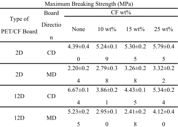
The maximum breaking strength of 2D-PET/CF composite boards and 12D-PET/CF composite boards are shown in Table 2. The number of base fabric layers contained in each type of PET/CF composite boards is 10. With large amount of finer fibers in each 2D-PETF, the 2D-PET/CF composite board is able to maintain considerable amount of thermal bonding spots among the neighboring 2D-PETF layers in the sandwich-like structures. Therefore, after the thermal bonding process, the CF layers can be effectively wrapped by the neighboring 2D-PETF layers to attenuate the reduction of fiber-to-fiber cohesion related to the poor interfacial adhesion between the CF and polyester fiber. As a result, the maximum breaking strength of 2D-PET/CF composite board increases in both CD and MD in comparison to that of 2D PET board as seen from Table 2. Also, the maximum breaking strength of 2D-PET/CF composite board increases with the increased amount of CF. As for 12D-PET/CF composite board, due to the crimped feature and fewer fibers in each 12D-PETF, the thermal bonding force among the neighboring 2D-PETF layers is unable to effectively wrap the CF layers in the sandwich-like structures. In turn, the fiber-to-fiber cohesion among the laminated layers is noticeably
reduced in the sandwich-like structures. Therefore, the maximum breaking strength of 12D-PET/CF composite board is less than that of 12D-PET board as indicated in Table 2. When the amount of CF increases from 10 wt% to 25 wt %, the effects of CF quantities on the maximum breaking strength of 12D-PET/CF composite board are similar to that of 2D-12D-PET/CF composite board.
Table 2. The maximum breaking strength of 2D-PET/CF and 12D-PET/CF boards versus the amount of CF. (Heating temperature: 130oC; Heating time: 10 min; number of base PET nonwoven fabric layers: 10; basis weight of one PET nonwoven fabric layer: 200±10 g/m2; board thickness: 10mm)
Maximum Breaking Strength (MPa) Type of PET/CF Board Board Directio n CF wt% None 10 wt% 15 wt% 25 wt% 2D CD 4.39±0.4 0 5.24±0.1 9 5.30±0.2 5 5.79±0.4 5 2D MD 2.20±0.2 4 2.79±0.3 8 3.26±0.2 8 3.32±0.2 2 12D CD 6.67±0.1 4 3.86±0.2 1 4.43±0.1 5 5.34±0.2 4 12D MD 5.23±0.2 5 2.95±0.1 0 2.41±0.2 8 4.12±0.4 0 * The “None” column represents the value for PET board with 10 base
PET nonwoven fabric layers
The Influence of the Laminated Layer’s Number and Amount of CF on the Air Permeability
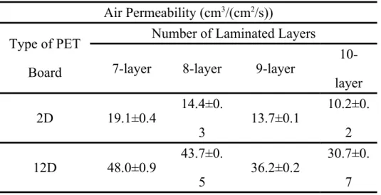
The air permeability of 2D-PET and 12D-PET boards is listed in Table 3. Apparently, the air permeability of 2D-PET board is lower than that of 12D-PET board. Since the 2D polyester fiber is finer than the 12D fire retarded three-dimensional hollow crimp polyester fiber, the structure of 2D-PET board is much denser and tighter than that of 12D-PET board in the comparison of the same board thickness. As a result, the smaller size and volume fraction of air voids make the 2D-PET board less air permeable than 12D-PET board. Moreover, as the number of laminated layers increases, the structure of the PET board becomes more compact and denser. The air passages through the interconnected pores also become more tortuous. Clearly, as seen from Table 3, when the number of laminated PET nonwoven fabric layers increases, the air permeability for both PET boards decreases.
Table 3. The air permeability of 2D-PET and 12D-PET boards versus the number of laminated numbers. (Heating temperature: 130oC; Heating time: 10
min; basis weight of one PET nonwoven fabric layer: 200±10 g/m2; board thickness: 10 mm)
Air Permeability (cm3/(cm2/s)) Type of PET
Board
Number of Laminated Layers
7-layer 8-layer 9-layer
10-layer 2D 19.1±0.4 14.4±0. 3 13.7±0.1 10.2±0. 2 12D 48.0±0.9 43.7±0. 5 36.2±0.2 30.7±0. 7
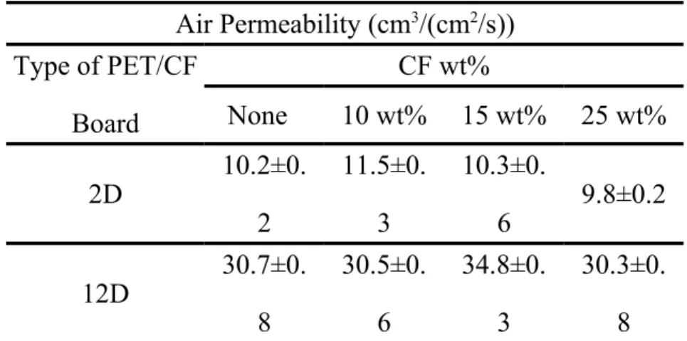
Table 4 shows the test results for the air permeability of 2D-PET/CF and 12D-PET/CF composite boards. Each type of PET/CF composite boards contains 10 base PET nonwoven fabric layers and 3 CF layers. As the amount of CF increases, the denser and tighter structure of the PET/CF composite board tends to make the PET/CF composite board less air permeable. However, the much looser sandwich-like structures from 4th to 7th base layers and the porous features of CF noticeably reduce the negative impact of increased amount of CF on the air permeability of PET/CF composite board. Therefore, little difference in the air permeability is observed for both 2D-PET/CF and 12D-PET/CF composite boards as seen from Table 4.
Table 4. The air permeability of 2D-PET/CF and 12D-PET/CF boards versus the amount of CF. (Heating temperature: 130 oC; Heating time: 10 min; number of base PET nonwoven fabric layers: 10; basis weight of one PET nonwoven fabric layer: 200 ±10 g/m2; board thickness: 10mm)
Air Permeability (cm3/(cm2/s)) Type of PET/CF Board CF wt% None 10 wt% 15 wt% 25 wt% 2D 10.2±0. 2 11.5±0. 3 10.3±0. 6 9.8±0.2 12D 30.7±0. 8 30.5±0. 6 34.8±0. 3 30.3±0. 8 * The “None” column represents the value for PET board
with 10 base PET nonwoven fabric layers
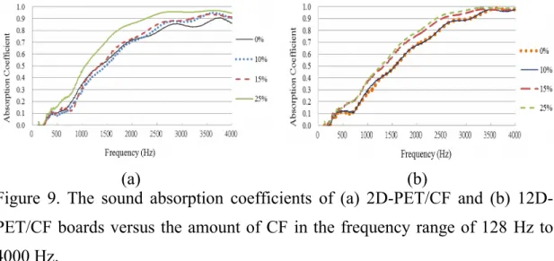
Figures 9(a) and 9(b) respectively display the test results of the sound absorption coefficients of 2D-PET/CF and 12D-PET/CF composite boards in the frequency range of 128 Hz to 4000 Hz. Moreover, Table 5 shows the relationship between the amount of CF and the average sound absorption coefficients of 2D-PET/CF and 12D-PET/CF composite boards. Apparently, the average sound absorption performance of both the 2D-PET/CF and 12D-PET/CF composite boards increases with the increased amount of CF. It is also observed that the sound absorption coefficient of 2D-PET/CF composite board dramatically increases when the amount of CF is 25 wt%. When the thickness keeps at 10 mm, the structure of PET/CF composite board becomes more and more compact as the amount of CF increases. Although the increased amount of CF tends to make the PET/CF composite board more rigid, the PET/CF composite board still allows the majority of sound waves enter through the resulted compact porous structure based on the air permeability test results from Table 4. The compact structure not only reduces the size and volume fraction of air voids but also makes the air passages much narrower and more tortuous. Therefore, the compact structure forces the sound wave passing through the PET/CF composite board to travel longer distance. Consequently, more reduction of sound energy resulting from the viscous flow losses and internal friction losses enhances the sound absorption performance for the PET/CF composite board. In short, the sound absorption performance for both the 2D-PET/CF and 12D-PET/CF composite boards is strengthened by adding CF.
(a) (b)
Figure 9. The sound absorption coefficients of (a) 2D-PET/CF and (b) 12D-PET/CF boards versus the amount of CF in the frequency range of 128 Hz to 4000 Hz.
Table 5. The sound absorption coefficients of 2D-PET/CF and 12D-PET/CF boards versus the amount of CF. (Heating temperature: 130 oC; Heating time: 10 min; number of base PET nonwoven fabric layers: 10; basis weight of one PET nonwoven fabric layer: 200±10 g/m2; board thickness: 10 mm)
Average sound absorption coefficient Type of PET/CF Board CF wt% None 10 wt% 15 wt% 25 wt% 2D 0.600 0.604 0.623 0.711 12D 0.605 0.607 0.666 0.681
* The “None” column represents the value for PET board with 10 base PET nonwoven fabric layers
The Influence of the Amount of CF on Limiting Oxygen Index
The test results for the LOI values of 2D-PET/CF and 12D-PET/CF composite boards are shown in Table 6. The LOI values of 2D-PET and 12D-PET boards are respectively measured as 33 and 32. As the amount of CF increases, the tighter and denser structure of PET/CF composite boards tends to reduce the size and volume fraction of air voids within the structure. Accordingly, the amount of combustion-supporting gas contained within the
structure of PET/CF composite board is subjected to be less dense. As a result, the LOI value of PET/CF composite board is expected to increase with the added amount of CF in comparison with the one of the PET board. However, as seen from Table 6, the LOI values for both 2D-PET/CF and 12D-PET/CF composite boards are actually declining due to the flammable and porous features of CF. Furthermore, since the 12D-PET/CF composite board is more bulky than the 2D-PET/CF one, the larger size and volume fraction of air voids keep more air within its structure. Owing to the coating of flame-retardant agent on the surface of 12D fire retardant three-dimensional hollow crimp polyester fiber, the LOI values between 2D-PET/CF and 12D-PET/CF composite boards show little difference as seen in Table 6. For both types of PET/CF composite boards, the flame retardance still meets the requirement of self-extinguishing standard (LOI: 26 %~34 %).
Table 6. The LOI of 2D-PET/CF and 12D-PET/CF boards versus the amount of CF. (Heating temperature: 130oC; Heating time: 10 min; number of base
PET nonwoven fabric layers: 10; basis weight of one PET nonwoven fabric layer: 200±10 g/m2; board thickness: 10mm)
Limiting Oxygen Index Type of PET/CF Board CF wt% None 10 wt% 15 wt% 25 wt% 2D 33 27 28 28 12D 32 28 28 28
* The “None” column represents the value for PET board with 10 base PET nonwoven fabric layers
The Influence of the Amount of CF on Thermal Conductivity Coefficient The thermal conductivity coefficients of 2D-PET/CF and 12D-PET/CF composite boards are depicted in Table 7. It is observed that the overall trend for thermal conductivity coefficient of the 2D-PET/CF composite board increases with the increased amount of CF (CF less than 15 wt%). As the amount of CF increases, the narrow and tortuous air passages are more likely to obstruct the airflow. The reduced heat convection resulting from the obstructed airflow leads to better thermal insulation performance for the 2D-PET/CF composite board. In the mean time, even though the size and volume fraction of air voids in the 2D-PET/CF composite board have been reduced, the porous features of CF enable the 2D-PET/CF composite board to retain certain amount of static air and subsequently to maintain its thermal insulation performance. However, the tighter and denser structure of the 2D-PET/CF composite board tremendously increases the surface contact among fibers, which facilitates the heat conduction through fibers and cause significant decrease in the thermal insulation performance of 2D-PET/CF composite board. As a result, the overall
thermal conductivity coefficient tends to increases with the increased amount of CF less than 15 wt% as shown in Table 7.
It is observed that the 12D-PET/CF composite board with 10 wt% of CF has better thermal insulation performance in comparison to the 12D-PET board. The larger size and volume fraction of air voids in the 12D-PET board foster the heat convection to smoothly go through air passages. When adding 10 wt% CF, the reduced size and volume fraction of air voids in the 12D-PET/CF composite board make the air passages narrower and more tortuous. This obstructs the airflow and then significantly decreases the heat convection. Meanwhile, the static air in the hollow CF also helps maintain the thermal insulation performance of the 12D-PET/CF composite board to some degree.
Although the structure of the PET/CF board becomes more compact and denser as 10 wt% of CF is added, the crimped behavior of 12D fire retarded three-dimensional hollow crimp polyester fiber effectively restrains the increased entanglements and surface contact among fibers between the CF layer and 12D-PETF layer. Namely, the increase in heat conduction through fibers is limited. Therefore, the 12D-PET/CF composite board with 10 wt% of CF has lower thermal conductivity coefficient than the 12D-PET board. When the amount of CF increases from 10 wt% to 25 wt%, the effects of CF quantities on the thermal conductivity coefficient of 12D-PET/CF composite board are similar to that of 2D-PET/CF composite board. For both types of PET/CF composite boards, the measured thermal conductivity coefficients range from 0.0284 W/mK to 0.0495 W/mK. The standard requirement of thermal conductivity coefficient is in the range of 0.03-0.17 W/mK for a
thermal insulating material. It is clear that each type of PET/CF composite board possesses excellent thermal insulation property.
Table 7. The thermal conductive coefficients of 2D-PET/CF and 12D-PET/CF boards versus the amount of CF. (Heating temperature: 130 oC; Heating time: 10 min; number of base PET nonwoven fabric layers: 10; basis weight of one PET nonwoven fabric layer: 200±10 g/m2; board thickness: 10 mm)
Thermal conductivity coefficient (W/mK) Type of PET/CF Board CF wt% None 10 wt% 15 wt% 25 wt% 2D 0.0279 0.0445 0.0495 0.0419 12D 0.0467 0.0284 0.0410 0.0340
* The “None” column represents the value for PET board with 10 base PET nonwoven fabric layers
Conclusion
The purpose of this study is to investigate the effects of CF on PET nonwoven composite board in terms of the maximum breaking strength, air permeability, sound absorption coefficient, LOI, and thermal insulation coefficient. Each type of PET boards with 10 PET nonwoven fabric layers is used as the control group to examine the efficacy of CF on different types of PET/CF composite boards. For 2D-PET/CF composite board, the maximum breaking strength increases 31.89% in CD. On the other hand, the maximum breaking strength of 12D-PET/CF composite board decreases 19.94% in CD. In terms of air permeability, the amount of CF shows little impacts on both types of PET/CF composite board. As for the sound absorption performance, the
average sound coefficients respectively increase 18.5% and 12.5% for the 2D-PET/CF and the 12D-2D-PET/CF composite boards when the amount of CF is 25 wt%. As the CF is introduced, the LOI value decreases for both types of PET/CF composite boards. Both types of the PET/CF composite boards possess excellent thermal conductivity coefficients ranging from 0.0279 to 0.0495. In future work, the key research issue pertains to improve sound absorption performance in low frequency range by adhering a thermoplastic polyurethane (TPU) film on the surface of the PET/CF composite board since low frequency noise is the most harmful to human health.
Reference
1. L. L. Beranek and I. L. Vér, Noise and Vibration Control Engineering:
2. C. W. Lou, P. Chen and J. H. Lin, Advanced Materials Research, 55-57, 393, 2008.
3. K. Watanabe, Y. Minemura, K. Nemoto and H. Sugawara, JSAE Review, 20, 357, 1999.
4. J. P. Parkinson, J. R. Pearse and M. D. Latimer, Applied Acoustics, 63, 819, 2002.
5. J. H. Lin, P. Chen and C. W. Lou, Advanced Materials Research, 55-57, 393, 2008.
6. C. W. Lou, P. Chen and J. H. Lin, The 10th Asian Textile Conference
(ATC-10), G5-O-08, 186, 2009.
7. Y. C. Liao, C. C. Lin, C. W. Lou and J. H. Lin, The 10th Asian Textile
Conference (ATC-10), G2-O-33, 103, 2009.
8. J. H. Lin, Y. C. Liao, C. C. Huang, C. C. Lin, C. M. Lin and C. W. Lou,
Advanced Materials Research, 97-101, 1801, 2010.
9. K. C. Tai, P. Chen, C. W. Lin, C. W. Lou, H. M. Tan and J. H. Lin,
Advanced Materials Research, 123-125, 475, 2010.
10. Y. Lee and C. Joo, AUTEX Research Journal, 3(2), 2003.
11. H. Zhou, B. Li, G. S. Huang and J. He, Journal of Sound and Vibration, 304, 400, 2007.
12. A. K. Mohanty, M. Misra, and L. T. Drzal, Natural Fibers, Biopolymers
and Biocomposites, Taylor & Francis, 875, 2005.
13. N. Ayrilmis, S. Jarusombuti, V. Fueangvivat, P. Bauchongkol and R. H. White, Fibers and Polymers, 12(7), 919, 2011.
14. M. J. M. Nor, M. Ayub, R. Zulkifli, N. Amin and M. H. Fouladi, Journal
of Applied Sciences, 10, 2887, 2010.
15. M. H. Fouladi, M. Ghassem, M. Ayub, and M. J. M. Nor, Noise &
Vibration Worldwide, 42(9), 11, 2011.
16. C. M. Lin, C. W. Lou and J. H. Lin, Textile Research Journal, 79(11), 993, 2009.
17. C. W. Lou, C. W. Lin, C. C. Lin, S. J. Li, I. J. Tsai and J. H. Lin,
Advanced Materials Research, 55-57, 405, 2008.
18. I. J. Tsai, C. H. Lei, C. H. Lee, Y. C. Lee, C. W. Lou and J. H. Lin,
Journal of Materials Processing Technology, 192-193, 415, 2007.
19. J. H. Lin, C. H. Huang, K. C. Tai, C. C. Lin, Y. T. Tsai and C. W. Lou,