國立高雄大學應用物理學研究所
碩士論文
探討加熱溶液與甲酸多重處理對
PEDOT:PSS 薄膜之
改善
Investigation of solution heating and formic acid multiple
treatment for improvement of the PEDOT:PSS film
研究生 : 許博勛
指導教授 : 黃建榮 博士
I
探討加熱溶液與甲酸多重處理對
PEDOT:PSS 薄膜之
改善
指導教授 : 黃建榮博士 國立高雄大學應用物理學系 學生 : 許博勛 國立高雄大學應用物理學系摘要
在本研究中,我們提出一個加熱攪拌的簡單方法去優化聚(3,4-聚二氧乙基 噻吩)-聚(苯乙烯磺酸) (PEDOT:PSS) 溶液,由於加熱攪拌 PEDOT:PSS 溶液能 蒸發溶液中的水份,PEDOT 與 PSS 之間的結構將會變的更加緊密。加熱攪拌PEDOT:PSS 溶液之後,PEDOT:PSS 薄膜的電流密度從 0.52nA/μm2 增加到
6.91nA/μm2,比原始的薄膜多了 13 倍,這不僅能增加 PEDOT:PSS 薄膜的導電 率,還能改善 PEDOT:PSS 薄膜的品質。PEDOT:PSS 薄膜的黏滯力從35nN 減少到 7nN,換句話說也就是薄膜的硬度增加了,這是一個能夠同時改善電特性與薄膜 品質的一個有效方法。 為了進一步改善 PEDOT:PSS 薄膜的導電率,在 PEDOT:PSS 薄膜表面執行 甲酸的多重處理,PEDOT:PSS 薄膜的導電率從 0.3 S cm−1 增加到1763 S cm−1超 過三個數量級,而在甲酸多重處理後PEDOT:PSS 薄膜的穿透率仍維持在 80%。 甲酸多重處理能夠增加 PEDOT:PSS 導電率是因為甲酸的高介電常數屏蔽了 PEDOT 與 PSS 之間的電荷導致他們相分離,然後 PEDOT 鍵從捲曲變成線性。 然而構象的改變、從薄膜中去除PSS 和三維導電網路的形成,是導電率增加的主 要機制。 關鍵詞 : 聚二氧乙基噻吩-聚苯乙烯磺酸、加熱攪拌、結構緊密、甲酸處理、多 重處理
II
Investigation of solution heating and formic acid
multiple treatment for improvement of the
PEDOT:PSS film
Advisor(s) : Dr. Chien-Jung Huang Institute of Applied Physics National University of Kaohsiung
Student : Po-Husn Hsu Institute of Applied Physics National University of Kaohsiung
Abstract
In this study, a simple method to optimize the poly(3,4-ethylenedioxythiophene):poly(styrenesulfonate) (PEDOT:PSS) solution by heating and stirring was been proposed. The structure between PEDOT and PSS was closer, because heating and stirring the PEDOT:PSS solution will evaporate the water in solution. The current density of PEDOT:PSS film was enhanced from 0.52 nA/μm2 to 6.91 nA/μm2
by 13 times greater than pristine film after heating and stirring the PEDOT:PSS solution. It can not only increase the conductivity but also change the quality of PEDOT:PSS film. The adhesion of PEDOT:PSS film was decreased from 35 nN to 7 nN. In other words, the hardness of film has increased. It’s an effective method to improve the quality and electrical properties of the film simultaneously.
To improve the conductivity of PEDOT:PSS film further, Formic acid multiple treatment was carried in surface of PEDOT:PSS film. The conductivity of PEDOT:PSS film was enhanced from 0.3 S cm−1 to 1763 S cm−1 by more than three orders of
magnitude, and the transmittance of PEDOT:PSS film still maintained 80 % after formic acid multiple treatment. Formic acid multiple treatment can enhance the
III
conductivity of PEDOT:PSS due to the fact that its high dielectric constant screens the charge between PEDOT and PSS bringing about phase separation between them, and the PEDOT chains change from coiled to linear. However, the conformational change, the removal of PSS from the film and a three-dimensional conducting network are the mechanisms of conductivity enhancement.
Keywords : PEDOT:PSS, heating and stirring, structure closer, formic acid treatment, multiple treatment
IV
致謝
回首兩年的研究所時光,就如當初引薦我進來就讀的高秉詳學長所說的, 兩年的時間說長不長說短不短,但所獲所學卻是滿滿,感謝當初剛進實驗室還懵 懵懂懂時,千娪學姊一路的新手教學,讓我能夠快速的熟悉實驗室的生態環境, 在實驗的過程中教導我如何自行探索與操作,保勛學長的行政能力,讓我學到專 業知識以外的收穫,就如他常說的這都是自己的選擇,讀了五年的博士班,因此 讓他有如行政助理般的能幹,還有在遇到艱深的英文問題時,憑著他的經驗幫我 一一解惑,也謝謝已經畢業的中喬學長,還不時回來探望學弟妹給予支持鼓勵與 加菜,還有隔壁實驗室的同學偉銘和盈翔,陪伴我兩年碩班的歡樂時光,讓我的 人生又能增添兩位摯友,也感謝爸爸媽媽對我的支持,不論是精神上還是金錢上, 讓我能如此無後顧之憂的學習,和我女朋友家君這一路上的陪伴,讓我在奮鬥的 過程中不迷惘,僅此致上我心中的感謝。許博勛 敬上 107.08.21
V
Table of Contents
Chinese Abstract………...I English Abstract………...II Acknowledgements……….IV Table of Contents……….V List of Figures………..VIII List of Tables………...XIChapter1 Introduction
………...11-1 The history of PEDOT:PSS………..1
1-2 Motivation………...2
Chapter 2 Theory of PEDOT: PSS
………...32-1 Conductive polymers……….………...3
2-2 Structure of PEDOT:PSS………...………..…3
2-3 Conductive mechanism of PEDOT:PSS………..…4
2-4 Conductive improvement of PEDOT:PSS………...4
2-5 Application of PEDOT:PSS……….……5
Chapter 3 Experiments
………..…..63-1 Materials………..…6
3-2 Preparation………...…6
3-2-1 Substrate………...…6
3-2-2 Optimize solution of PEDOT:PSS………7
3-2-3 Spin-coating………..……7
3-3 Acid treatment………..……7
VI
3-3-2 Immerse acid treatment………8
3-3-3 Multiple acid treatment………8
3-4 Plasma patterning……….9
3-5 Measurements………..…9
Chapter 4 Results and Discussions
……….114-1 Optimize the PEDOT:PSS solution by heating and stirring………..…11
4-1-1 Effects on solution………..…11
4-1-2 Effects on optical properties………...11
4-1-3 Effects on films surface……….……….………12
4-1-4 Effects on films morphology……….……….……13
4-1-5 Effects on films adhesion………...……14
4-1-6 Effects on films conductivity……….…15
4-1-7 Effects on film binding energy………..15
4-2 Improve film conductivity of PEDOT:PSS by formic acid multiple treatment.16 4-2-1 Method of formic acid treatment………16
4-2-2 Effect on optical properties and sheet resistance………17
4-2-3 Effect on atomic ratio……….…18
4-2-4 Effect on films surface………..….….19
4-2-5 Effects on films morphology………..…19
4-2-6 Effects on details of Formic Acid multiple treatment……….……20
4-2-7 Conductive mechanism of formic acid multiple treatment……….…21
4-3 Pattern of PEDOT:PSS film by oxygen plasma………21
4-3-1 Oxygen plasma………...……21
4-3-2 Plasma Ashing with Oxygen………..……22
4-3-3 Oxygen Plasma with Argon………22
VII
Chapter 5 Conclusion and future work
……….235-1 Conclusion……….23
5-2 Future work………24
VIII
List of Figures
Figure 2.1 The chemical structure of PEDOT:PSS……….………..30 Figure 2.2 The conductive mechanism reaction of the PEDOT and the PSS……….31 Figure 3.1 The Chemical structure of formic acid……….32 Figure3.2 The schematic illustration of cleaned the glass substrates and
treated with Oxygen plasma………...…….33 Figure 3.3 The schematic illustration of oxygen plasma surface modification……..34 Figure 3.4 The schematic illustration of optimize the PEDOT:PSS solution by filter
andheating and stirring...……….………..….35 Figure 3.5 The schematic illustration ofspin-coating and baked in oven…………..36 Figure 3.6 The schematic illustration of film rinsed with DI water………...37 Figure 3.7 The schematic illustration ofspin-coating and baked in oven……….….38
Figure 3.8 The schematic illustration of formic acid immerse treatment………...…39 Figure 3.9 The schematic illustration of formic acid multiple treatment………..…40 Figure 3.10 The schematic illustration of oxygen plasma patterning…………..…..41
Figure 4.1 The schematic illustration of heating and stirring processing comparison to multiple spin-coating processing. ………...…42 Figure 4.2 The schematic illustration of structure change by heating and stirring.43
Figure 4.3 The schematic illustration of particle size changed after heating and
stirring………...….44 Figure 4.4 The variation of PEDOT:PSS film thickness and solution amount with
time of heating and stirring at 100 °C, 200 rpm….………45 Figure 4.5 The variation of transmittance and solution amount with time of heating
and stirring at 100 °C, 200 rpm……….46 Figure 4.6 The SEM top view images of PEDOT:PSS films heating at 100 °C in
IX
different stirring times: (a) 0 min, (b) 10 min, (c) 18 min, (d) 22 min. All the scale in the image are 10 μm………..…………47 Figure 4.7 The EDS image of white particles in SEM images of the PEDOT:PSS
films. ………..…48 Figure 4.8 SEM top view images of PEDOT:PSS films formed with 65% amount
solution after heating at 200 rpm with different temperatures and times: (a)50 °C, 100min, (b) 100 °C, 22 min and (c) 150 °C, 8.5 min. All the scale in the image are 10μm………...49 Figure 4.9 The AFM topographic images of PEDOT:PSS films heating at 100 °C, 200
rpm with different stirring times: (a) 0 min, (b) 10 min, (c) 18 min, and (d) 22 min. All the images are 1 μm × 1 μm………..………...……50 Figure 4.10 AFM 3D topographic images of PEDOT:PSS films heating at 100 °C,
200 rpm with different stirring times: (a) 0 min, (b) 10 min, (c) 18 min, and (d) 22 min. All the images are 1 μm × 1 μm.……….………51 Figure 4.11 The AFM adhesion map of PEDOT:PSS films heating at 100 °C, 200 rpm
with different stirring times: : (a) 0 min, (b) 10 min, (c) 18 min, and (d) 22 min. All the images are 1 μm × 1 μm.………...…52 Figure 4.12 The AFM schematic representation of a force curve, and important events
in the measurement of adhesion.………..…..….53 Figure 4.13 The AFM current images of PEDOT:PSS films heating at 100 °C,
200 rpm with different stirring times: (a) 0 min, (b) 10 min, (c) 18 min and (d) 22 min. All the images are 1μm × 1 μm. ………...………54 Figure 4.14 The current density and longitudinal conductivity depend on time of
heating stirring. ………55 Figure 4.15 The XPS spectra of pristine and solution optimized of PEDOT:PSS films
………..56 Figure 4.16 The conductivity of PEDOT:PSS film by formic acid treatment with four
different methods. ………57 Figure4.17 The variation of sheet resistance and transmittance with time of heating
and stirring at 100 °C, 200 rpm after formic acid multiple treatment…58 Figure 4.18 The UV-Vis-NIR absorption spectroscopy of PEDOT:PSS films with the
X
different method of formic acid treatments………59 Figure 4.19 The XPS sulfur (2p) spectra of PEDOT:PSS films with different treated
methods of formic acid.………..………60 Figure 4.20 The XPS oxygen (O) 1s spectra of PEDOT:PSS films with different
treated methods of formic acid. ………61 Figure 4.21 The SEM images of PEDOT:PSS films: (a) pristine, (b) treated with
immersing formic acid, (c) treated with dropping formic acid and (d) treated with DAIFA. All the scale bars in the image are 1 μm × 1 μm……….62 Figure 4.22 The AFM images of PEDOT:PSS films: (a) pristine, (b) treated with
immersing formic acid, (c) treated with dropping formic acid and (d) treated with DAIFA. The images are topographic images. All the images are 1 μm × 1 μm. ………...……63 Figure4.23 The variation of transmittance and sheet resistance with immersion time
in DAIFA treatment of PEDOTPSS film……….………64 Figure 4.24 The schematic illustration of PEDOT:PSS film transmittance after formic
acid treatment……….………..………65 Figure4.25 The schematic illustration of PEDOT:PSS film after DAIFA treatment………...………..…………..66 Figure 4.26 The results of PEDOT:PSS film pattern by oxygen plasma………….67
XI
List of Table
Table 4.1 The costs in processing of heating and stirring compared with the multilayer film. ………..……68 Table 4.2 The solution amount and solution concentration of PEDOT:PSS with time of heating and stirring at 100 °C, 200 rpm………...……..69 Table 4.3 The heating temperatures corresponds to the heating time stirring at 200 r p m t o m a k e t h e 6 5 % s o l u t i o n a m o u n t o f P E D O T : P S S solution………...……70 Table 4.4 The roughness of PEDOT:PSS films corresponds to heating time stirring at 200 rpm, 100 °C……….…71 Table 4.5 The current density and longitudinal conductivity in PEDOT:PSS films depend on time of heating stirring. ………72 Table 4.6 The reduction in film thickness by different treatment method of formic acid. ………73 Table 4.7 The influence on ratio of PEDOT to PSS in PEDOT:PSS film by different
treatment method of formic acid………...…74 Table 4.8 The influence on ratio of PEDOT to PSS in PEDOT:PSS film by different
1
Chapter 1
Introduction
1-1 The history of PEDOT: PSS
With the development of science and technology, flexibility is a fashionable and ideal feature of future consumable electronic product, which is widely used in our life such as touch screen, wearable devices, liquid crystal displays, organic light emitting diodes (OLEDs) and organic solar cells [1,2]. However, the main problem for developing flexible electronic products is the limitation of the flexible transparent electrode. Also, the transparent conductive film material commonly-used indium tin oxide (ITO) have a lot of problems. For example, the cost is high, the mechanical flexibility is poor, and the high vacuum deposition is required, resulting in the limitation of flexibility and large-area production. Therefore, the ITO is not suitable for flexible devices
In 1977, Alan J. Heeger, Alan G. MacDiarmid and Hideki Shirakawa discovered that doped polyacetylene has metallic conductivity (103 S cm - 1) [3]. Conductive
polymers have the structure with a conjugated π bond of long-chain. It's presence the external electric field after doping the chemical solvent. The carriers can directional migration along the conjugated π bond to achieve the charge transmission [4]. Afterwards, Bayer AG invented the PEDOT in 1988 [5]. The conducting polymers PEDOT have special properties that are interesting for new technology. They not only have the electronic properties of semiconductor, but also have the mechanical flexibility of plastic. Moreover, conjugated polymers are good materials to be employed in the fabrication of electronic devices. Because their properties such as disorder can also be tuned by external parameters during chemical synthesis within a certain band width. The PEDOT:PSS commonly used to replace the ITO in light-emitting diode,
2
photovoltaic device and transistors due to the reasonable conductivity and thermal stability [6-9].
In recent decades, PEDOT:PSS has shown wide application prospects in the light-emitting diodes, transistors, electrochromic, solar cells, sensor, energy storage, and thermoelectric conversion [10-12]. More than 1000 research papers related with PEDOT research have published each year [13-15].
1-2 Motivation
The quality and characteristics of transparent conductive films are important factors in determination the performance and application of consumer electronics. Especially in the flexibility of electrodes which are necessary for wearable devices and curved screen commonly used in the future. PEDOT is quite promising as a next-generation transparent electrode material due to fact that its low cost, non-toxic, easy processing and mechanical flexibility can achieve cost-effective and flexible devices as well as roll-to-roll mass production [16-17]. However, pure conductive PEDOT is difficult to process due to its insolubility in water, it can still be dispersed in water by the coulomb interaction with the counterion of the insulating PSS. The concentration ratio of PEDOT:PSS solution to water have only 1.0-1.3 wt%. Therefore, the pristine conductivity of PEDOT:PSS is poor due to the fact that the conductive PEDOT is dispersed in excess water, resulting in the limitation of carrier transmission. In this study, a simple method to remove excess water in PEDOT:PSS solution was studied by heating and stirring. The mechanism of conductivity improvements in PEDOT:PSS film by further formic acid multiple treatment was also necessary to investigation.
3
Chapter 2
Theory of PEDOT: PSS
2-1 Conductive polymers
Conductive polymers are organic polymers that conduct electricity. Such compounds have metallic conductivity or property of semiconductors. The advantage of conductive polymers was easy processing by dispersion in water. Conductive polymers are generally not thermoplastics. But they are organic materials like insulating polymers. The conductive polymers have the structure with a conjugated π bond of long-chain. It's presence the external electric field after doping the chemical solvent. The carriers can directional migration along the conjugated π bond to achieve the charge transmission [4]. The common used in conductive polymers are: polyaniline, polypyrrole, polythiophene, polyacetylene, and derivatives thereof.
2-2 Structure of PEDOT:PSS
The commonly used PEDOT:PSS solution is a complex materials system. In order to circumvent the poor solubility and infusibility of pure PEDOT, it is polymerized in the presence of water-soluble polyelectrolyte PSS that acts as a dopant and counterion and facilitates the formation of a stable aqueous colloidal solution [15]. Generally, these colloidal particles are described as entangles of PSS chains with PEDOT oligomer units adsorbed to them. When in aqueous solution, the hydrophobicity of the adsorbed PEDOT driving preferential orientation of the hydrophilic sulfate groups to the outside and the PEDOT-rich parts of the chain to the inside of the entangled polymer chain, causing a micelle-like formation. From the macroscopic point of view this results in a particle with a PEDOT-rich conductive core and an insulating PSS-rich shell, which has
4
been verified in numerous investigations on dried films [18-20]. The chemical structure of PEDOT:PSS is shown in Figure 2.1.
2-3 Conductive mechanism of PEDOT:PSS
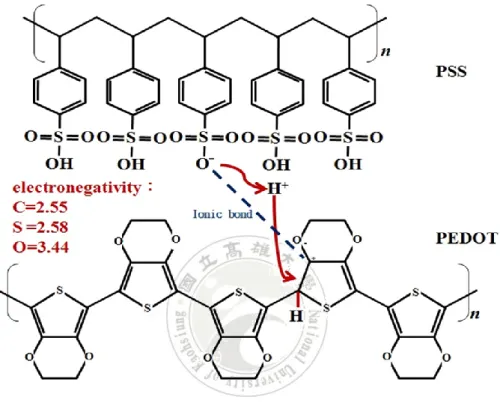
The reaction of the PEDOT and the PSS was shown in Figure 2.2. The -OH groups of the PSS structure were dissociated to H+ in the water. And the H+ actively attacked the double bond of the thiophene of the PEDOT to form hydrogen bonding. However, electrons of the C-O shared electron pairs were attracted by O due to its higher electronegativity. The phenomenon led to the fact that the C of the C-O bond became a positive charge. Finally, the ionic bond was formed between the C+ of the PEDOT structure and the O− of the PSS structure [21].
2-4 Conductive improvement of PEDOT:PSS
The concentration ratio of pristine PEDOT:PSS solution to water have only 1.0-1.3 wt%, resulting in the poor conductivity in PEDOT:PSS due to the fact that the conductive PEDOT is dispersed in excess water to limit the carrier transmission. Thus, it’s necessary to remove excess water in PEDOT:PSS solution, and make the structure closer to facilitate carrier transmission. However, only rely on the reduction of excess water in PEDOT:PSS solution is not enough to drastically improve the conductivity of PEDOT:PSS film. The colloidal particles of PEDOT:PSS are described as entangles of PSS chains with PEDOT oligomer units adsorbed to them. This results in a PEDOT:PSS particle with PEDOT-rich conductive core and insulating PSS-rich shell have poor conductivity. Thus, it necessary for remove the PSS form the PEDOT:PSS film to improve the conductivity of PEDOT:PSS film. The formic acid with high dielectric constant can effectively screens the charge between PEDOT and PSS to bringing about
5
phase separation between them, and the PEDOT chains change from coiled to linear. The conformational change, removal of PSS from the film and a three-dimensional conducting network formation are the mechanisms of conductivity enhancement.
2-5 Application of PEDOT:PSS
Organic electronics, or plastic electronics such as organic light-emitting diode (OLED), liquid crystal displays (LCDs), touch panel displays and wearable device are currently attracting much interest as a promising technology [22-26].These devices all have the transparent conductive film inside to affect its operation. The quality and characteristics of transparent conductive films are important factors in determination the performance and application of consumer electronics. Especially in the flexibility of electrodes which are necessary for wearable devices and curved screen commonly used in the future. The PEDOT:PSS films shows high transparency in the visible range, high mechanical flexibility, and excellent thermal stability and can be fabricated through conventional solution processing. It's a promising material in flexible electrodes to replace the transparent conductive film material commonly-used ITO.
6
Chapter 3
Experiments
3-1 Materials
The glass substrates (H384 UR-GLASS-0.7MM, 0.7mm) with an area of 4.3×4.3 cm2 was purchased form FlamegoldMaterial Co. The Clevios PH1000 PEDOT: PSS
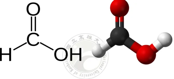
aqueous solution was purchased from Heraeus Co, has a PEDOT: PSS concentration of 1.0-1.3 wt%, and the weight ratio of PSS to PEDOT is 2.5. The filter (VHP01300) with 0.45 m pore size was purchased from SIGMA-ALDRICH. The 25 ml beaker (AK64030-00025) with 55 mm height and 30 mm inner diameter was purchased from DOGGER. The formic acid with 98% concentrations was purchased from SIGMA-ALDRICH. Chemical structure of formic acid was shown in Figure 3.1.
3-2 Preparation
3-2-1 Substrate
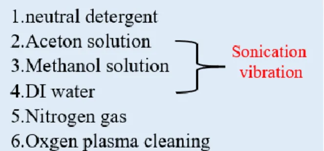
Pre-clean the substrate with a neutral detergent before sonication. After that, the glass substrates were cleaned with sonication in acetone, methanol and de-ionized (DI) water successively with 10 minutes for each cleaner, and then dried in an oven after blowing with N2 gas. The cleaned glass substrates were treated with Oxygen plasma for 30 w, 60 s. The schematic illustration of experiment was shown in Figure 3.2. Oxygen
plasma processing is a simple, low-cost, non-polluting surface treatment technology to clean and surface modification. The substrate can increase the surface energy after the oxygen plasma treatment, because C-O and C = O hydrophilic functional groups were introduced on the surface of the substrate. The surface energy increased in substrate result to the substrate more hydrophilic to reduce the contact angle of the solution with
7
the substrate and increase the adhesion in film to the substrate. The schematic illustration of oxygen plasma surface modification was shown in Figure 3.3.
3-2-2
Optimize solution of PEDOT:PSS
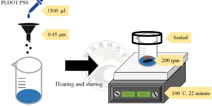
The PEDOT: PSS aqueous solution was filtered through a syringe filter (0.45 m pore size) to filter the impurities in the solution before use. Subsequently, the 1.5g of PEDOT:PSS solution in sealed beaker (AK64030-00025) was carried out by heated and stirred on a stirrers/hot plate (Corning PC-420D) to ensure homogeneous heat distribution. The heating and stirring of PEDOT:PSS solutions were carried out at 100
°C, 200 rpm for at time 22 minutes before further processing. The schematic illustration of experiment was shown in Figure 3.4. After heating and stirring, use a kimwipe to wipe the water vapor around in the beaker to prevent the water vapor from re-dropping into the solution.
3-2-3
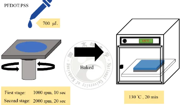
Spin-coating
The PEDOT:PSS solution after optimization was drop 700 l on the cleanly glass substrate and coated by spinner. The spin-coating was carried out at 1000 rpm, 2000 rpm for 10 secs and 20 secs to formed the PEDOT: PSS film. After that, the film of PEDOT:PSS was baked at 130 °C for 20 minutes in ambient conditions by oven. The schematic illustration of experiment was shown in Figure 3.5.
3-3 Acid treatment
3-3-1 Drop acid treatment
The acid treatment was carried out by dropping 450 l of formic acid on the PEDOT:PSS films, and the PEDOT:PSS film will heating at 130 °C for 7 minutes on
8
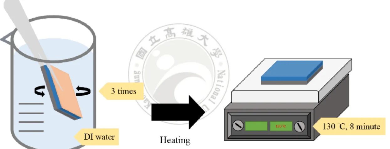
the stirrers/hot plate to dry the formic acid. The schematic illustration of formic acid drop treatment was shown in Figure 3.6. The PEDOT:PSS film were rinsed after acid treatment by using the method of stirring for three times in DI water and dried at 130 °C for 8 minutes on the stirrers/hot plate. The schematic illustration of film rinsed with DI water was shown in Figure 3.7.
3-3-2 Immerse acid treatment
The acid treatment was carried out by immerse the PEDOT:PSS film in formic acid, and the PEDOT:PSS film will heating at 130 °C for 7 minutes on the stirrers/hot plate to dry the formic acid. The formic acid must completely immersion the PEDOT:PSS film for 10 minutes. The schematic illustration of formic acid immerse treatment was shown in Figure 3.8. The PEDOT:PSS film were rinsed after acid treatment by using the method of stirring for three times in DI water and dried at 130 °C for 8 minutes on the stirrers/hot plate. The schematic illustration of film rinsed with DI water was shown in Figure 3.7.
3-3-3 Multiple acid treatment
The multiple acid treatment was carried out by drop after immerse formic acid (DAIFA). The film was immersed in formic acid for 10 minutes, cleaned by using the method of stirring for three times in DI water and dried at 130 °C for 8 minutes on the stirrers/hot plate. Afterward the film was treated with 450 l of formic acid drops on the film and cleaned by stirring for three times in DI water and dried at 130 °C for 8 minutes on the stirrers/hot plate. The schematic illustration of formic acid multiple treatment was shown in Figure 3.9.
9
3-4 Plasma patterning
The optimization of PEDOT:PSS film was covered with a stainless steel contact mash to protect. An oxygen plasma removed the unprotected parts of the PEDOT:PSS film for 30 w, 900 secs to obtain the desired shape of the anode. The schematic illustration of oxygen plasma patterning was shown in Figure 3.10.
3-5 Measurements
The conductivity enhancement mechanism of the PEDOT: PSS film was studied by various chemical and physical measurements. The changes in solution amount of PEDOT:PSS was measured by digital analytical balance (AND HR-200). The sheet resistance of PEDOT: PSS film were measured with four-point sheet resistivity meter (SRM103, Solar Energy Tech., Taiwan). The transmittance of PEDOT: PSS films were measured by UV/visible spectrometer (HITACHI, U-3900) at the wavelength of 550 nm. Film thickness of PEDOT: PSS film was measured using ellipsometer (J. A. Woolam / M2000-DI). The PEDOT to PSS ratio was measured by X-ray photoelectron spectrometer (XPS, JEOL, JAMP-9500F). The surface microscopic image of PEDOT:PSS film was measured by scanning electron microscope (SEM, JEOL JSM-7001). The surface morphology and roughness of PEDOT: PSS films were measured by atomic force microscopy (AFM, Park Systems, XE-70). The current image of PEDOT:PSS film was measured by conductive atomic force microscopes (C-AFM Bruker).
10
Chapter 4
Results and Discussions
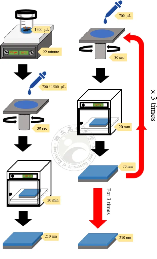
In this study, a simple method to remove excess water in PEDOT:PSS solution by heating and stirring was been proposed. The heating and stirring PEDOT:PSS solution can not only change the structure but also increase the conductivity of PEDOT:PSS film. It’s an effective method to improve the quality and electrical properties of the film simultaneously. The improvement of quality and electrical properties on the film will contribute to the stability and performance of electronic product when the component manufacturing. Compared with the multilayer film, the heating and stirring is also a good method to reduce the process time in multiple coating and baking of PEDOT:PSS films. It can spin-coating a same thickness of PEDOT:PSS monolayer film, because the viscosity of the PEDOT:PSS solution was increased by heating and stirring. The detailed comparison of experiment was shown in Figure 4.1 and Table 4.1. The effect of heating and stirring in film quality and performance will be discussed the details in this article. Conductive PEDOT is insoluble in most solvents, but it can be dispersed in water by using a counter ion of insulation PSS. However, in an aqueous dispersion of PEDOT:PSS, short PEDOT chains are surrounded by a thin PSS-rich surface layer, which is one of the main reasons for its low conductivity. PEDOT:PSS conductivity enhancement is strongly dependent on dielectric constants of the chemicals used for treatment solvents. Formic acid with its high dielectric constant screens the charge between PEDOT and PSS bringing about phase separation between them [27]. Further improve conductivity of the PEDOT:PSS film in second stage, the PSS was removed from the PEDOT: PSS film via twice formic acid treatments to enhance the conductivity without affecting its other desirable properties. The mechanism of twice different formic acid treatment PEDOT: PSS film will be presented.
11
4-1 Optimize the PEDOT:PSS solution by heating and stirring
4-1-1 Effects on solution
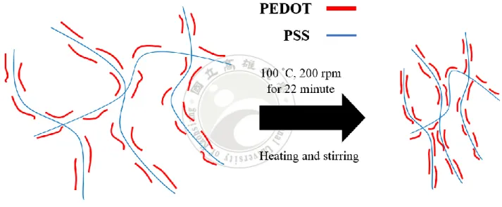
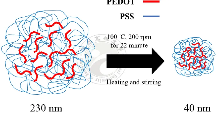
The method of heating and stirring the PEDOT:PSS solution can remove the excess water in solution by thermal evaporation, it not only remove the water in PEDOT:PSS solution but also make the structure between PEDOT and PSS closer. The schematic illustration of structure change was shown in Figure 4.2. The heating and stirring was also affect the particle size of PEDOT:PSS. Similar phenomenon for effect of heating temperature on particle size was reported by Bettina Friedl et al, 2011 [28]. The decreases in particle size of PEDOT:PSS form 230 nm to 40 nm after heating from 60 °C up to 90 °C, representing a size reduction of 83%. This allows the PEDOT:PSS particles to be more evenly dispersed in the film to conducive the charge transmission. The schematic illustration of particle size changed was shown in Figure 4.3. The viscosity of the PEDOT:PSS solution was also increased due to the evaporation of water in PEDOT:PSS by heating and stirring. The reduction in evaporation rate of PEDOT:PSS solution over time may be due to the saturation of the humidity in the sealed beaker. The solution amount and solution concentration of PEDOT:PSS with time of heating and stirring at 100 °C, 200 rpm were shown in Table 4.2. The spin-coating in same speed at 1000 rpm, 2000 rpm for 10 secs and 20 secs in the Figure 4.4 was shown the thickness of PEDOT:PSS film depends on the time of heating and stirring. As the viscosity of the PEDOT:PSS solution increases, the thickness of the PEDOT:PSS film was also increases because the high viscosity of solution was not easily to separate from the substrate by centrifugal force.
4-1-2 Effects on
optical properties
12
measured by UV/visible spectrometer at the wavelength of 550 nm. The Figure 4.5 show the variation of transmittance and solution amount with time of heating and stirring. As the time of heating and stirring was extended, the transmittance of PEDOT:PSS film will decrease due to the fact that increase in the viscosity of the PEDOT:PSS solution result an increase in the thickness of PEDOT:PSS film at constant speed of the spin-coating. The best parameter to optimize the PEDOT:PSS solution is the 65 % of the solution amount after heating and stirring at 100 °C for 22 minutes. The excessive time of heating and stirring will deplete of water in PEDOT:PSS solution, resulting that is difficult to form a intact film of PEDOT:PSS by spin-coating due to the agglomeration of PEDOT:PSS solution. It will also result in a transmittance of film less than 80 %, which is not preferred to be applied for transparent conductive electrodes in photovoltaic devices.
4-1-3 Effects on films
surface
The effects of heating and stirring on surface variation in PEDOT:PSS film was observed by SEM image. All the images size in SEM are 2000 magnification. The Figure 4.6 show the SEM top view images of PEDOT:PSS films heating at 100 °C in different stirring times. The white particles with 3% sulfur atom ratio in surface of PEDOT:PSS films were observed by the energy dispersive spectrometer (EDS) in Figure 4.7. This suggest that the many aggregate particles of PEDOT:PSS in PEDOT:PSS film can't uniform dispersed. This may form the defects to affect the performance of subsequent device production. Heating and stirring the PEDOT:PSS solution can decreases the particle size of PEDOT:PSS to induce uniform dispersed. The effect of heating and stirring to improve the uneven distribution of PEDOT:PSS particles was shown in Figure 4.6d. The white particles of PEDOT:PSS were disappeared nearly completely after heating at 100 °C for 22 minutes. The effect of
13
PEDOT:PSS particles with different heating temperatures in the same solution amount of 65% to improve the uniformity were also investigated in this study. The effect of optimize the PEDOT:PSS solution by heating and stirring at 50 °C, 100 °C and 150 °C were shown in Figure 4.8. The Figure 4.8b SEM top view images of PEDOT:PSS film shows the effects of heating and stirring at 100 °C different from the other temperatures. The Figure 4.8a shows the effect at a temperature of 50 °C, the PEDOT:PSS particles cannot be uniformly dissolved in the PEDOT:PSS solution due to the temperature insufficient, resulting in the white particles on the surface of PEDOT:PSS film were formed. The Figure 4.8c shows the effect at a temperature of 150 °C, the excessive temperature of heating will evaporate the water in PEDOT:PSS solution too fast, resulting in the white particles of PEDOT:PSS were not enough time to uniformly dissolved. In this study the optimal parameter to optimize the PEDOT:PSS solution at 100 °C was obtain. The heating temperatures corresponds to heating time stirring at 200 rpm were shown in Table 4.3.
4-1-4 Effects on films
morphology
The effects of heating and stirring on morphology variation in PEDOT:PSS film was observed by AFM image. All the images size in AFM are 1 μm × 1 μm. The Figure 4.9 show the clear changes in PEDOT:PSS films morphology of AFM images by heating at 100 °C, 200 rpm in different stirring times, and the 3 Dimensions (3D) topographic of AFM images were shown in Figure 4.10. Heating and stirring to remove the water in PEDOT:PSS solution will bring the PEDOT more near the film surface. There were seen to be more aggregated in morphology of PEDOT:PSS films by heating and stirring for longer periods in Figure 4.9d. The morphology AFM images show that the PEDOT:PSS films were slightly increased after heating and stirring for longer periods with root mean square (RMS) roughness of 1.21, 1.54, 1.68 and 1.85 nm. The
14
roughness of PEDOT:PSS films corresponds to heating time stirring at 200 rpm, 100 °C were shown in Table 4.4.
4-1-5 Effects on films
adhesion
The effects of heating and stirring on adhesion variation in PEDOT:PSS film was observed by AFM adhesion map. All the images size in AFM are 1 μm × 1 μm. The Figure 4.11 show the clear changes in PEDOT:PSS films morphology of adhesion map by heating at 100 °C, 200 rpm in different stirring times. There were seen to be more compaction and to darken in adhesion map of PEDOT:PSS films by heating and stirring for longer periods in Figure 4.11d. The adhesion of PEDOT:PSS films were also decreased from 35 nN to 7 nN after heating and stirring for 22 minutes, representing a adhesion reduction of 80%. Figure 4.12 is a schematic representation of a force curve, and important events in the measurement are numbered 1–5. Point 1 is the cantilever position above the surface before initiating the force curve. Once the measurement has begun, the cantilever is moved vertically toward the surface (red line) until it reaches point 2. This is called the jump-to-contact point, where attractive forces acting on the tip cause it to snap to the surface. Between point 2 and point 3, the cantilever deflects upward as the system continues moving toward the surface. This region may be analyzed to yield the stiffness and the elasticity (Young’ modulus) of a sample. Point 3 is the trigger point, which is specified in software, and when this point is reached, the system stops and starts to retract the cantilever from the surface. This setpoint controls the maximum force applied to the sample during the measurement. Point 4 is the snap off, which corresponds to the adhesion force. Point 5 is when the cantilever retracts to its initial starting position. The force curve measurements on the glass substrate showed little or no adhesion force [29]. The reduction of adhesion in PEDOT:PSS film can be used as evidence of the increased in film hardness.
15
4-1-6 Effects on films
conductivity
The effects of heating and stirring on conductivity in PEDOT:PSS film was observed by c-AFM current images. All the images size in AFM are 1 μm × 1 μm. Figure 4.13 illustrates that as the time of heating and stirring increases, there is both a strong increase in the total number of conductive pathways observed by c-AFM. The PEDOT:PSS films were increase rapidly the conductive hot-spots after heating and stirring due to the change of PEDOT:PSS structure. The heating and stirring to remove the water in PEDOT:PSS solution not only bring the PEDOT more near the film surface but also make the structure between PEDOT and PSS closer. The c-AFM current images show in Figure 4.13, the PEDOT:PSS films were increased the current density from 0.52, 4.10, 6.47 to 6.91 nA/μm2after heating and stirring for longer periods,
representing a current density was increased by 13 times more. The longitudinal conductivity of PEDOT:PSS films root mean square (rq) were also increased by7 times more from 0.96, 1.27, 6.12 to 6.69 nA/μm2 after heating and stirring for longer periods.
This suggests that vertical and transversal connectivity between the PEDOT grains is indeed improved, resulting in increased bulk conductivity attributed to an average decrease in the intergrain distance and increase in the number of interparticle connections [30-32]. The current density and longitudinal conductivity in PEDOT:PSS films depend on time of heating stirring were shown in Figure 4.14 and Table 4.5.
4-1-7 Effects on film binding energy
The effects of heating and stirring on binding energy in PEDOT:PSS film was measured by X-ray photoelectron spectrometer (XPS). XPS is a surface-sensitive technique, but no lateral resolution was examined due to fact that the size of the analyzed spot is about a few mm2. Both PEDOT and PSS contain one sulfur atom per
16
in PSS is included in the sulfonate moiety. Due to those different chemical environments, the S (2p) electrons of PEDOT and PSS have different binding energies so that the composition of PEDOT-PSS can be analyzed by XPS. The S (2p) peak at the binding energy between 167 to 171 eV originate from the sulfur atoms in PSS, and the doublet peaks at 164.4 and 165.6 eV corresponds to the sulfur signal of PEDOT were in Figure 4.15 [33]. The Figure 4.15 show the XPS spectra of pristine and solution optimized of PEDOT:PSS films. The binding energies of PEDOT in PEDOT:PSS film after solution optimized by heating and stirring at 100 °C for 22 minute has slight rise. The increased of bind energy in the conductive PEDOT measured under the same measurement range was attributed to a closer structure, that allows them to near more in the PEDOT:PSS film and beneficial to charge transmission.
4-2 Improve film conductivity of PEDOT:PSS by formic acid
multiple treatment
4-2-1 Method of formic acid treatment
The Figure 4.16 shows the conductivity of PEDOT:PSS film by formic acid treatment with four different methods. Formic acid treatment can effectively improve the conductivity of PEDOT:PSS film by more than three orders of magnitude. Among them, formic acid multiple treatment (drop after immerse formic acid, DAIFA) can increase the conductivity from 0.3 S cm−1 to 1763 S cm−1. Every kind of methods for
formic acid treatment have different effects on the PEDOT:PSS films. The dropping formic acid has a stronger reaction than immersing formic acid to remove PSS from the surface of the PEDOT:PSS film, but dropping formic acid can’t fully penetrate the PEDOT:PSS film to a deeper interior. On the other hand, immersing formic acid has no strong reaction to the surface of the PEDOT:PSS film but can penetrate deeper into the
17
interior of PEDOT:PSS film to screen the PSS. In addition, screening the PSS from the interior of the PEDOT:PSS film and bringing it to the surface, then treatment with stronger droppings on the surface can effectively remove the PSS from the PEDOT:PSS film. The synergy effect of formic acid twice treatment to improve the conductivity greater than any single treatment will be confirmed in this article.
4-2-2 Effect on optical properties and sheet resistance
Figure 4.17 shows the variation of sheet resistance and transmittance with heating and stirring time after formic acid multiple treatment. The structure of the PEDOT:PSS solution will be tighter due to the fact that the heating and stirring is a simple method to effectively remove excess water from PEDOT:PSS solution. The sheet resistance depends on the time of heating and stirring due to the variation in film thickness. The heating and stirring time at 22 minutes is also the best parameter for PEDOT:PSS solution multiple treatment by formic acid because the transmittance is more than 80%, which is preferred to be applied in devices. If the heating and stirring time exceeds 22 minutes, it will cause the solution to aggregate, resulting in a decrease in film quality and transmittance. In Figure 4.18, the PEDOT:PSS films with the different method of formic acid treatments were studied by the UV-Vis-NIR absorption spectroscopy. The two absorption bands in the UV range from 180 to 240 nm originate from PSS in PEDOT:PSS [34,35]. Figure 4.18 shows the changes in the absorption of PEDOT:PSS films by different treatments due to the loss of PSS chains. And then the reduction in film thickness is from 225 to 160 nm after DAIFA, i. e., there is the decrease of 29% being treated in DAIFA. For the other treatments of formic acid, the percentage in reduction of film thickness is less than 29%. The reduction in film thickness by different treatment method of formic acid were shown in Table 4.6. Interestingly, whatever the percentage in reduction of film thickness becomes small, the transparency of
18
PEDOT:PSS films is unchanged because of the PSS chains being transparent.
4-2-3 Effect on atomic ratio
Figure 4.19 shows the XPS spectra of pristine PEDOT:PSS and different treated methods with formic acid. The sulfur (2p) peak at the binding energy between 167 to 171 eV originate from the sulfur atoms in PSS, and the doublet peaks at 164.4 and 165.6 eV corresponds to the sulfur signal of PEDOT [33]. The ratio changes in PEDOT and PSS were obviously influenced by the fluctuation of sulfur band (S, 2p) from XPS result. The PEDOT:PSS ratio was calculated by calculating the area under each peak using full width at half-maximum (FWHM) curve fitting. The ratio of PEDOT to PSS increased from 1:2.68 before film treatment to 1:1.38 after film treatment by immersing formic acid, 1:1.27 by dropping formic acid and even increased further to 1:1.21 after treating by DAIFA, which is up to 55% PSS removal from the film surface. The influence on ratio of PEDOT to PSS in PEDOT:PSS film by different treatment method of formic acid were shown in Table 4.7. The two peaks in Figure 4.20 at 532.9 and 531.2 eV are the O peaks from PEDOT and PSS, respectively [18]. For the oxygen (O) 1s spectra as shown in Figure 4.20, the bimodal peak can be depicted in two peaks at around 529–535 eV corresponding to the oxygen atoms in the PEDOT units in higher binding energy regions (532.9 eV), whereas the oxygen atoms in the PSS units give their characteristic peaks in relatively lower binding energy regions (531.9 eV) [36]. The PSS peak became smaller and broadened to the lower energy level after formic acid treatment. It can be observed from this Figure 4.20 that under various methods of formic acid treatment have different effects to remove the PSS from PEDOT: PSS film. It also pointed out that the best results were achieved to screen PSS in the DAIFA treatment.
19
4-2-4 Effect on films
surface
Figure 4.21 shows the SEM images of PEDOT:PSS films treated with different methods of formic acid. It can be observed that the surface of the PEDOT:PSS films has the appearance of the besmirch with micrometer size after the various treatments of formic acid, i. e. , the reacting between formic acid and PEDOT:PSS film. The large area of besmirch reveals that DAIFA treatment can effectively screens PSS from PEDOT:PSS film better than that of other methods. The aggregation of PSS chains formed the besmirch on the surface of film, and they can be washed away with (DI) water. Upon further investigation through energy-dispersive X-ray spectroscopy (EDX), it was found that there are the ingredients of sulfur and oxygen atom in the PEDOT:PSS film. If sulfur atom is unilaterally observed, then sulfur atoms can’t be distinguished between PEDOT and PSS. In addition, oxygen atom from formic acid was absorbed by the hygroscopic polyelectrolyte PSS. This characteristic for hydrophobic PEDOT doesn’t have [24]. Presumably, these besmirch are made of PSSH, which indicates that formic acid can induce the phase separation of some PSS chains from PEDOT:PSS films. This is due to the fact that the interaction between the positively charged PEDOT chains and the acid anions is probably stronger than that of between PEDOT and PSS. Consequently, the protons of the acid are transferred to PSS, so that PSS becomes PSSH and leaves the PEDOT:PSS film as the result of the disappearance of the coulombic interaction between PEDOT and PSSH [37]. One thing worth mentioning is that this phenomenon was also observed after the many acid treatment [38,39].
4-2-5 Effects on films
morphology
The AFM images show that there is clear change in the film morphology after treatment with formic acid, as shown in Figure 4.22. In the image, the brighter (positive) and dark (negative) phase shifts correspond to PEDOT-rich grains and PSS-rich grains,
20
respectively [40]. The topographic AFM images show that the films were quite smooth with root mean square (RMS) roughness of 1.82, 1.94, 2.14, and 2.15 nm before and after treatment with dropping formic acid, immersing formic acid and DAIFA, respectively in the Table 4.8. In Figure 4.22(d), PEDOT chains were seen to be more aggregated after DAIFA treatment. The screening effect of formic acid treatment will facilitate the phase separation between the PEDOT and PSS chains. The depletion of insulating PSS leads to a 3D conducting network of highly conductive PEDOT. Thus, the energy barrier for inter-chain and inter domain charge hopping will be lowered, resulting that charge transmission among the PEDOT chains is easy. The compact and wide distribution PEDOT-rich grains facilitate charge transfer, eventually there will be a tremendously enhanced conductivity.
4-2-6 Effects on details of Formic Acid multiple treatment
It is demonstrated that the DAIFA treatment of formic acid can effectively remove excess PSS to increase the conductivity. However, the immersion of formic acid has an absolute effect on the characteristic of the PEDOT:PSS thin films. Proper immersion of the formic acid can usefully separate PSS in the deep of the PEDOT:PSS film. But longer immersion time of formic acid was harmful to PEDOT:PSS film. Figure 4.23 shows the sheet resistance and transmittance in various immersion times. Firstly, with the increase of immersion time, the conductivity of PEDOT:PSS thin films has arisen due to the separation of deeper PSS. Second, the deep PEDOT will also be separated from PSS and the structure of PEDOT will change from curl to stretch even disperse within the films, which will further decrease the sheet resistance. When the time of immersion is more than 10 minutes, it will cause a rise in sheet resistance. the transmittance and hygroscopicity have slightly decreased and swelling respectively because the opaque PEDOT would block the light and hydrophilic PSS would absorb
21
too much water molecules. The schematic illustration of film transmittance after formic acid treatment was shown in Figure 4.24. Therefore, immersion time will be an important note to determine the quality and conductivity of PEDOT:PSS film.
4-2-7 Conductive mechanism of formic acid multiple treatment
Conductivity enhancement is strongly dependent on dielectric constants of the chemicals used for treatment; solvents with higher dielectric constants induce a stronger screening effect between counterions and charge carriers, which in turn reduces the Coulomb interaction between positively charged PEDOT and negatively charged PSS dopants [27]. The DAIFA treatment with its high dielectric constant screens the charge between PEDOT and PSS bringing about phase separation between them. Increased carrier concentration, the conformational change, removal of PSS from the PEDOT:PSS film and a three-dimensional conducting network are the mechanisms of conductivity enhancement. The schematic illustration of PEDOT:PSS film after DAIFA treatment was shown in Figure 4.25.
4-3 Pattern of PEDOT:PSS film by oxygen plasma
4-3-1 Oxygen plasma
Oxygen plasma refers to any plasma treatment performed while introducing oxygen to the plasma chamber. Oxygen is often used to clean surfaces prior to bonding. It may also be combined with other gases to etch a variety of materials such as plastic and rubber. Oxygen is the most common gas used in plasma cleaning technology due to its low cost and wide availability. Oxygen plasma will clean the surface of a plastic sample and increase its wettability, it can also be used to clean metal surfaces if it's mixed with Argon, Argon gas strips the oxygen molecule away from the metal to
22 prevent oxidation.
4-3-2 Plasma Ashing with Oxygen
Plasma ashing is the process of removing carbon from products during the manufacturing process. Plasma ashing is always performed with oxygen plasma in a high frequency plasma system. Generally, the goal of plasma ashing is to completely remove organic matter, including volatile carbon oxides and water vapor. All removed contaminants are pumped out of the chamber by the vacuum system. Oxygen plasma removes all traces of organic matter and leaves no residues unless there were excessive inorganic contaminants on the sample.
4-3-3 Oxygen Plasma with Argon
Another gas commonly used for plasma treatment is argon. The most notable difference between oxygen and argon is that oxygen plasma is capable of surface modification, while argon is not. Additionally, oxygen will etch while argon will only clean. If left in the plasma for too long, oxygen may modify the surface of some plastics rendering them unbendable, however argon is safe to use for longer periods of time.
4-3-4 Patterned PEDOT:PSS film by oxygen plasma
The PEDOT:PSS film had been patterned by oxygen plasma etching without affecting its other desirable properties. The PEDOT:PSS film with 35 Ω /square and 80% transmittance are keep same before and after etching. One of the main points of oxygen plasma etching was make the mask fit on the film tightly. This prevents the oxygen ions penetrating from the gap of mask and etch the pre-retained of PEDOT:PSS film to affect the conductivity. The results of PEDOT:PSS film etching by oxygen plasma was shown in Figure 4.26.
23
Chapter 5
Conclusion and future work
5-1 Conclusion
In summary, we have shown the effect of heating and stirring the PEDOT:PSS solution and various surface treatments of formic acid on the electrical properties, optical properties, films surface and morphology of PEDOT:PSS films. a simple method to optimize the PEDOT:PSS solution by heating and stirring was been proposed. The structure between PEDOT and PSS was closer, because heating and stirring the PEDOT:PSS solution will evaporate the water in solution. The current density of PEDOT:PSS film was enhanced from 0.52 nA/μm2 to 6.91 nA/μm2 by 13 times greater
than pristine film after heating and stirring the PEDOT:PSS solution. It can not only increase the conductivity but also change the quality of PEDOT:PSS film. The adhesion of PEDOT:PSS film was decreased from 35 nN to 7 nN. In other words, the hardness of film has increased. It’s an effective method to improve the quality and electrical properties of the film simultaneously.
To improve the conductivity of PEDOT:PSS film further, The DAIFA treatment can effectively remove the PSS from PEDOT:PSS film. Up to PSS of 55% was removed after DAIFA treatment. The conductivity increased from 0.3 S cm−1 to 1763 S cm−1 by
more than three orders of magnitude and maintained as high as transmittance of 80 % with sheet resistance of 35 Ω /squre. To enhance the conductivity of PEDOT: PSS, the DAIFA treatment with its high dielectric constant screens the charge between PEDOT and PSS bringing about phase separation between them. The conformational changes are the main mechanisms of conductivity enhancement. The roll-to-roll processability, which also is a determining factor for the cost of devices, is highly dependent on electrodes of the devices. In this study, the process of PEDOT:PSS film is different from
24
the commonly used multilayer film. The single film of high quality in shorter process time can be obtained, which is better than that of multilayer film by the heating and stirring during the process. DAIFA treatment is confirmed as a candidate as a simple process and high quality technique for conductive monolayer film to have more applications in future consumer products.
5-1 Future work
In above study, the PEDOT: PSS films were successfully improved through heating and stirring and multiple treatment. The sheet resistance of PEDOT: PSS film is 35 ohm/square, and the transmittance of PEDOT: PSS film is 80.1%. In the future works, the conductivity of PEDOT: PSS film will be further improved by using carbon nanotube. The improvement of PEDOT: PSS films will be substituted for ITO electrode as the anode of organic photoelectric devices. The PEDOT: PSS film has a great advantage of mechanical flexibility than the ITO film. Thus, the PEDOT: PSS film can be also applied to flexible organic solar cells and flexible organic light-emitting diodes. The ultimate goal of the research is “flexible organic optoelectronic components.”
25
References
[1]. Chipman, A., A commodity no more. Nature 2007, 449, (7159), 131-131.
[2]. Xia, Y.; Sun, K.; Ouyang, J., Solution‐processed metallic conducting polymer films as transparent electrode of optoelectronic devices. Advanced Materials 2012, 24, (18), 2436-2440.
[3]. Shirakawa, H.; Louis, E. J.; MacDiarmid, A. G.; Chiang, C. K.; Heeger, A. J., Synthesis of electrically conducting organic polymers: halogen derivatives of polyacetylene,(CH) x. Journal of the Chemical Society, Chemical Communications 1977, (16), 578-580.
[4]. Chiang, C. K.; Fincher Jr, C.; Park, Y. W.; Heeger, A. J.; Shirakawa, H.; Louis, E. J.; Gau, S. C.; MacDiarmid, A. G., Electrical conductivity in doped polyacetylene. Physical review letters 1977, 39, (17), 1098.
[5]. Groenendaal, L.; Jonas, F.; Freitag, D.; Pielartzik, H.; Reynolds, J. R., Poly (3, 4‐ ethylenedioxythiophene) and its derivatives: past, present, and future. Advanced materials 2000, 12, (7), 481-494.
[6]. Yin, Z.; Zheng, Q., Controlled Synthesis and Energy Applications of One ‐ Dimensional Conducting Polymer Nanostructures: An Overview. Advanced Energy Materials 2012, 2, (2), 179-218.
[7]. Wang, C.; Dong, H.; Hu, W.; Liu, Y.; Zhu, D., Semiconducting π-conjugated systems in field-effect transistors: a material odyssey of organic electronics. Chemical Reviews 2011, 112, (4), 2208-2267.
[8]. Snook, G. A.; Kao, P.; Best, A. S., Conducting-polymer-based supercapacitor devices and electrodes. Journal of Power Sources 2011, 196, (1), 1-12.
26
conducting polymers/nanocomposites for sensor applications. Sensors and Actuators B: Chemical 2009, 136, (1), 275-286.
[10]. Malti, A.; Gabrielsson, E. O.; Crispin, X.; Berggren, M., An electrochromic bipolar membrane diode. Advanced Materials 2015, 27, (26), 3909-3914.
[11]. Gupta, D.; Wienk, M. M.; Janssen, R. A., Efficient polymer solar cells on opaque substrates with a laminated PEDOT: PSS top electrode. Advanced Energy Materials 2013, 3, (6), 782-787.
[12]. Zhang, F.; Zang, Y.; Huang, D.; Di, C.-a.; Zhu, D., Flexible and self-powered temperature–pressure dual-parameter sensors using microstructure-frame-supported organic thermoelectric materials. Nature communications 2015, 6, 8356.
[13]. Groenendaal, L.; Zotti, G.; Aubert, P. H.; Waybright, S. M.; Reynolds, J. R., Electrochemistry of poly (3, 4 ‐ alkylenedioxythiophene) derivatives. Advanced Materials 2003, 15, (11), 855-879.
[14]. Chen, Y.; Zhao, Y.; Liang, Z., Solution processed organic thermoelectrics: towards flexible thermoelectric modules. Energy & Environmental Science 2015, 8, (2), 401-422.
[15]. Kirchmeyer, S.; Reuter, K., Scientific importance, properties and growing applications of poly (3, 4-ethylenedioxythiophene). Journal of Materials Chemistry 2005, 15, (21), 2077-2088.
[16]. Søndergaard, R.; Hösel, M.; Angmo, D.; Larsen-Olsen, T. T.; Krebs, F. C., Roll-to-roll fabrication of polymer solar cells. Materials today 2012, 15, (1-2), 36-49. [17]. Han, T.-H.; Lee, Y.; Choi, M.-R.; Woo, S.-H.; Bae, S.-H.; Hong, B. H.; Ahn, J.-H.; Lee, T.-W., Extremely efficient flexible organic light-emitting diodes with modified graphene anode. Nature Photonics 2012, 6, (2), 105.
[18]. Greczynski, G.; Kugler, T.; Keil, M.; Osikowicz, W.; Fahlman, M.; Salaneck, W. R., Photoelectron spectroscopy of thin films of PEDOT–PSS conjugated polymer blend:
27
a mini-review and some new results. Journal of Electron Spectroscopy and Related Phenomena 2001, 121, (1-3), 1-17.
[19]. Crispin, X.; Marciniak, S.; Osikowicz, W.; Zotti, G.; Van Der Gon, A. D.; Louwet, F.; Fahlman, M.; Groenendaal, L.; De Schryver, F.; Salaneck, W. R., Conductivity, morphology, interfacial chemistry, and stability of poly (3, 4‐ethylene dioxythiophene)– poly (styrene sulfonate): A photoelectron spectroscopy study. Journal of polymer science Part B: Polymer physics 2003, 41, (21), 2561-2583.
[20]. Kemerink, M.; Timpanaro, S.; De Kok, M.; Meulenkamp, E.; Touwslager, F., Three-dimensional inhomogeneities in PEDOT: PSS films. The Journal of Physical Chemistry B 2004, 108, (49), 18820-18825.
[21]. Meen, T.-H.; Chen, K.-L.; Chen, Y.-H.; Chen, W.-R.; Chou, D.-W.; Lan, W.-H.; Huang, C.-J., The Effects of dilute sulfuric acid on sheet resistance and transmittance in poly (3, 4-thylenedioxythiophene): poly (styrenesulfonate) films. International Journal of Photoenergy 2013, 2013.
[22]. Kim, T. Y.; Lee, T. H.; Kim, W. J.; Kim, J. E.; Suh, K. S. In Liquid crystal distortion in LCD panels and their solution using a conductive polymer, Electrical Overstress/Electrostatic Discharge Symposium, 2008. EOS/ESD 2008. 30th, 2008; IEEE: 2008; pp 191-195.
[23]. Kim, W.; Mäkinen, A.; Nikolov, N.; Shashidhar, R.; Kim, H.; Kafafi, Z., Molecular organic light-emitting diodes using highly conducting polymers as anodes. Applied Physics Letters 2002, 80, (20), 3844-3846.
[24]. Crispin, X.; Jakobsson, F.; Crispin, A.; Grim, P.; Andersson, P.; Volodin, A.; Van Haesendonck, C.; Van der Auweraer, M.; Salaneck, W. R.; Berggren, M., The origin of the high conductivity of poly (3, 4-ethylenedioxythiophene)− poly (styrenesulfonate)(PEDOT− PSS) plastic electrodes. Chemistry of Materials 2006, 18, (18), 4354-4360.
28
[25]. Crawford, G., Flexible flat panel displays. John Wiley & Sons: 2005.
[26]. Honda, W.; Harada, S.; Arie, T.; Akita, S.; Takei, K., Wearable, human‐interactive, health ‐ monitoring, wireless devices fabricated by macroscale printing techniques. Advanced Functional Materials 2014, 24, (22), 3299-3304.
[27]. Kim, J.; Jung, J.; Lee, D.; Joo, J., Enhancement of electrical conductivity of poly (3, 4-ethylenedioxythiophene)/poly (4-styrenesulfonate) by a change of solvents. Synthetic Metals 2002, 126, (2-3), 311-316.
[28]. Friedel, B.; Brenner, T. J.; McNeill, C. R.; Steiner, U.; Greenham, N. C., Influence of solution heating on the properties of PEDOT: PSS colloidal solutions and impact on the device performance of polymer solar cells. Organic electronics 2011, 12, (10), 1736-1745.
[29]. Hsieh, S.; Li, I.-T.; Hsieh, W.; Kung, M.-L.; Hsieh, S.-L.; Wu, D.-C.; Kuo, C.-H.; Tai, M.-C.-H.; Wang, H.-M.; Wu, W.-J., Advances in cellular nanoscale force detection and manipulation. Arabian Journal of Chemistry 2015.
[30]. Huang, J.; Miller, P. F.; Wilson, J. S.; de Mello, A. J.; de Mello, J. C.; Bradley, D. D., Investigation of the effects of doping and post ‐ deposition treatments on the conductivity, morphology, and work function of poly (3, 4 ‐ ethylenedioxythiophene)/poly (styrene sulfonate) films. Advanced Functional Materials 2005, 15, (2), 290-296.
[31]. De Jong, M.; Van Ijzendoorn, L.; De Voigt, M., Stability of the interface between indium-tin-oxide and poly (3, 4-ethylenedioxythiophene)/poly (styrenesulfonate) in polymer light-emitting diodes. Applied Physics Letters 2000, 77, (14), 2255-2257. [32]. Pingree, L. S.; MacLeod, B. A.; Ginger, D. S., The changing face of PEDOT: PSS films: substrate, bias, and processing effects on vertical charge transport. The Journal of Physical Chemistry C 2008, 112, (21), 7922-7927.
29
D.-Y., Evolution of nanomorphology and anisotropic conductivity in solvent-modified PEDOT: PSS films for polymeric anodes of polymer solar cells. Journal of Materials Chemistry 2009, 19, (47), 9045-9053.
[34]. Bae, S.; Kim, H.; Lee, Y.; Xu, X.; Park, J.-S.; Zheng, Y.; Balakrishnan, J.; Lei, T.; Kim, H. R.; Song, Y. I., Roll-to-roll production of 30-inch graphene films for transparent electrodes. Nature nanotechnology 2010, 5, (8), 574.
[35]. Kim, Y. H.; Sachse, C.; Machala, M. L.; May, C.; Müller‐Meskamp, L.; Leo, K., Highly conductive PEDOT: PSS electrode with optimized solvent and thermal post‐ treatment for ITO‐free organic solar cells. Advanced Functional Materials 2011, 21, (6), 1076-1081.
[36]. Park, H.; Lee, S. H.; Kim, F. S.; Choi, H. H.; Cheong, I. W.; Kim, J. H., Enhanced thermoelectric properties of PEDOT: PSS nanofilms by a chemical dedoping process. Journal of Materials Chemistry A 2014, 2, (18), 6532-6539.
[37]. Mengistie, D. A.; Ibrahem, M. A.; Wang, P.-C.; Chu, C.-W., Highly conductive PEDOT: PSS treated with formic acid for ITO-free polymer solar cells. ACS applied materials & interfaces 2014, 6, (4), 2292-2299.
[38]. Xia, Y.; Ouyang, J., Significant conductivity enhancement of conductive poly (3, 4-ethylenedioxythiophene): poly (styrenesulfonate) films through a treatment with organic carboxylic acids and inorganic acids. ACS applied materials & interfaces 2010, 2, (2), 474-483.
[39]. Xia, Y.; Ouyang, J., PEDOT: PSS films with significantly enhanced conductivities induced by preferential solvation with cosolvents and their application in polymer photovoltaic cells. Journal of Materials Chemistry 2011, 21, (13), 4927-4936.
[40]. Lang, U.; Müller, E.; Naujoks, N.; Dual, J., Microscopical investigations of PEDOT: PSS thin films. Advanced Functional Materials 2009, 19, (8), 1215-1220.
30
31
32
33
Figure 3.2 The schematic illustration of cleaned the glass substrates and treated with Oxygen plasma.
d
34
35
Figure 3.4 The schematic illustration ofoptimize the PEDOT:PSS solution by filter andheating and stirring.
36
37
38
39
40
41
42
Figure 4.1 The schematic illustration of heating and stirring processing comparison to multiple spin-coating processing.
43
44
45
Figure 4.4 The variation of PEDOT:PSS film thickness and solution amount with time of heating and stirring at 100 °C, 200 rpm.
46
Figure 4.5 The variation of transmittance and solution amount with time of heating and stirring at 100 °C, 200 rpm.
47
Figure 4.6 The SEM top view images of PEDOT:PSS films heating at 100 °C in different stirring times: (a) 0 min, (b) 10 min, (c) 18 min, (d) 22 min. All the scale in the image are 10 μm.
48
49
Figure 4.8 SEM top view images of PEDOT:PSS films formed with 65% amount solution after heating at 200 rpm with different temperatures and times: (a) 50 °C, 100min, (b) 100° C, 22 min and (c) 150 °C, 8.5 min. All the scale in the image are 10 μm.
50
Figure 4.9 The AFM topographic images of PEDOT:PSS films heating at 100 °C, 200 rpm with different stirring times: (a) 0 min, (b) 10 min, (c) 18 min, and (d) 22 min. All the images are 1 μm × 1 μm.
51
Figure 4.10 The AFM 3D topographic images of PEDOT:PSS films heating at 100 °C, 200 rpm with different stirring times: (a) 0 min, (b) 10 min, (c) 18 min, and (d) 22 min. All the images are 1 μm × 1 μm.