THP-1 O(T2)
A design of scanning system based
on
the aspherical lens
C.Y.Jhuang, J.Y.Chen, T.D.Cheng
National Taiwan universality
Room
433,
Institution of Applied Mechanics, NTU,
F., Sec. 4,
Roosevelt Rd., Da-an
District, Taipei City
106,
Taiwan (R.O.C.)
+88602-33665646, +88602-33665638, [email protected],
[email protected],
[email protected]
Abstract
--
The goal of this research is implementing the aspherical lens to design a scanning system. It is proposed to make the bio-optical sysfem possess the higher resolution that spherical can 't achieve.INTRODUCTION
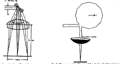
This topic is about optical system design for a biochip scanner. First of all, a light source incident on a rotating dodecahedron mirror, and bended by this rotating mirror. In fig. 1, the designed lenses can focus the incident beam on the specified position. In addition, light can be focused on a spot in the specific range by rotating the dodecahedron mirror. In this article, the commercial software, CODE V, is used to simulate to obtain the best performance.
ANALYTICAL MODEL
In this system there are some goals to be achieved, the distance between the light source and the rotating mirror is about 20-25cm. The geometric figure of the dodecahedron mirror is in fig 2. The radius of incident light is one of the designed parameter. Distance between the dodecahedron mirror and the focal plane is about 10-15 cm, the scanning range is about 7.62 cm, the spot size is smaller than 5pm, and the scanning linearity will be optimized. In order to achieve these goals, the aspheric lenses are adopted in this scanning system.
i--*u,_.J
fig 1. optical configurationI
-
fig 2. The geometric figure of the dodecahedron mirror
RESULT AND DISCUSSION
In the beginning, eleven surface between stop and image surface are inserted. By changing each surface properties such as thickness, material, surface type, and tilting angle, etc, the preliminary scanning system could be obtained. There are some requirements must be checked, one is spot size, and the other is linearity. From the data list by the software, the maximum spot size is about 3.5 ~ m , which is smaller than 5pm. Furthermore, the scanning linearity is taken into account, The better linearity means that the distance between each spots would
0-7803-8676-0/04/$20.00 02004 IEEE
THP-1
O(T2)
X
Y Max=6.392I
Min=6. IO7OW 2$0.@@05 l.BOO0 l t S O O O 0.0 IUF 1m 0 . 0 1.8OW 1.1001) 0.oow 0.00v0 i 3 . ~ 9 ~ i.8onp i.800~ 0.0 - b . i o m 7 - b . t 0 % ~ 7 0.6 1 . 8 0 ~ 1.doao L$O.OOOS 2so.000~ 2 93.6394 1 . 8 0 0 2 2.5510 0.0 -998105.7 -3911105.7 0 . 0 1.1000 1.8000 259.2944 259.2944 3 0.ODOb 1.BOOI 3.6131 0 . 0 -713413.5 -733453.5 0.0 1.1504 1.0000 jb2.9338 351.933 4 -16.9185 1.8004 3.6134 0.1 -133155.5 -733453.5 b . 0 1.PwO 1.8OQO 351.9158 352.9338
s i i . s m 1.eooz 3.61% 0.0 -O.IOIIO? - o . m i d 0.0 1.aooO 1 . 8 6 0 ~ 266.aos3 056.0063 B -11.9542 1.8002 s . m o 0.0 1060475.9 1 0 ~ 4 7 5 . 9 0.0 1 . 0 0 ~ I.BOOD - Z ~ ~ . O W Z - m . o m
B -ZO.YW 1 . 8 0 0 ~ 2 . o e i i 0.0 i a 1 o m . 4 i0109m.# 0.0 i.tow i.som -zss.?914 - Z S S . O ~ ~ ~ 7 0.0000 1.8002 2.0011 0 . 0 1010917.4 1010917.4 0.0 1,8004 l.8WD -255.9914 -255.9?14 9 -9.1894 1.8003 1.8012 0.0 936535.08 95653S.06 0 . 0 1.8OW I.1OOB -216.9509 -276.3509
10 -++62+7 1.9436 2.1230 0.0 43.2484 45.3734 0.V 0.001p V q O O $ t -13.2413 -1S.3233 11 -2.8061 2.1851 2.76335 0 . 0 11.8475 90.1Z19 0 . 0 Q.QOS9 O.aO3D -41.S47a -3D.lZY9 12 - 8 4 . 9 7 3 9 2.2691 2,7001 0 . 0 15.5656 86.1919 0 . 0 0.00% V.0030 -15,56551 -66.1917 I W o . 4 ~ ~ 2 ~ . i s m n.0 21.?011 3 9 . s ~ 0.0 a.ons3 0.0037 - z u m s -19.5~16
Form the above data, the incident beam that expands the radius to 4" incidents into the designed lenses. The x part and y part of Gaussian beam waist radius are 2.4pm and 1.7pm respectively. So it has succeed to achieve all of requirements. They include that the spot size is smaller than 5pm, the linearity maintains in the specified range (0.28mm), and scanning range is 62.56mm.
CONCLUSIONS
The scanning system with higher solution has been designed. The aspherical lenses are adopted to achieve the high performance. The small spot size and the optimized linearity are obtained in the result. For the next stage of this optical system development, the less aspheical lens that ensures the better performance and less cost will be developed. The ultimate goal is to acquire system capabilities for more application.
REFERENCES
[ I ] Warren J. Smith, Modern OpticalEngineering, McGraw-Hill, New York (2000)
[Z] Paul R. Yoder, Ir.,Opto-mechonicalsy~te~ design, Marcel Dekker, Inc., New York (1993)
[3] Eugene Hecht, Optics, Addison Wesley, New York (2002)