Int J Adv Manuf Technol DOI 10.1007/s00170-005-0291-7
O R I G I N A L A RT I C L E
Chun-Fong You . Pei-Jung Tsou . Shen-Chou Yeh
Collaborative design for an assembly via the Internet
Received: 16 February 2004 / Accepted: 7 July 2005 / Published online: 21 January 2006 # Springer-Verlag London Limited 2006
Abstract This investigation proposes the architecture for a collaborative assembly design to shorten the life cycle in product development stages. The architecture adopts STEP-based data representation and CAD feature extrac-tion to enable the implementaextrac-tion of engineering change over the Internet. The collaborative design framework and design change propagation method, which are key to the proposed architecture, are discussed and implemented. The collaborative design approach can greatly shorten a product’s life cycle and improve the productivity of an enterprise. Keywords Collaborative design . Assembly design . Design change propagation . Product life cycle
1 Introduction
Engineering change plays an important role in the environ-ment of concurrent engineering and involves all activities related to design and manufacturing. Engineering change is frequently time-consuming since it often involves some distributed information systems and raises various issues concerning the product life cycle. This investigation pro-poses the architecture for propagating the engineering of change and a mechanism for managing the relationship between CAD and product data management (PDM) systems to shorten the time needed for engineering change. Engineering change is implemented through CAD and PDM systems using the manufacturing features which are critical to the product model. The proposed collaborative architecture follows STEP (STandard Exchange of Product data model) AP224 to define the standard-based feature. The same feature definition is also applied by the PDM system to guarantee the exchangeability of data. All
propagation of data between CAD and PDM systems is executed over the Internet, following the design change propagation methodology.
2 Review
The architecture presented herein is that of a web-based CAD/PDM integrator. Information about parts is stored in the server and all collaborative activities are performed over the Internet. Some studies have concentrated on the approach to a collaborative design framework and methods of propagating design changes. Huang and Mak [1] de-scribed the Internet with a structure that is divided into two parts: server and client. The server performs complex computation and the client is just a viewer of the solution received from the server.
Shyamsundar and Gadh’s [2] work concerned a three-tier architecture that includes the client, an application server (AS) and an intelligent server (IS), whereby the intelligent server is treated as an agent which manages the data information between the client and the application server.
In most off-the-shelf assembly systems, assembly models just records the information regarding faces for the mating conditions among the parts in the assembly model. Since the information based on the face definition does not suffice to reflect the modification of part shape well, the design changes in an assembly model can’t prop-agate properly and completely.
Noort et al. [3] provided a feature that communicates between parts and assembly. A feature is the high-level information in the CAD system such as pad, pocket, shaft and groove, for example. Modifying the data about each feature enables the part model to capture the geometric changes and update the appearance of the parts immediately. When the constraints of the mating conditions in the assembly model are assigned, the related features and faces of the parts are stored. If the feature of parts changes, the pertinent feature data in an assembly model can be searched and altered. Combining the part and assembly
C.-F. You (*) . P.-J. Tsou . S.-C. Yeh Department of Mechanical Engineering, National Taiwan University,
Taipei, Taiwan, 106, Republic of China e-mail: [email protected]
Tel.: +886-2-3631755 Fax: +886-2-3631755
model with the feature can solve the problem of prop-agating design changes. Other studies of the feature model include that of Mascle [4], while Sung’s [5] defined the assembly feature.
Design change (DC) may be propagated through the related feature, if the shape of the feature is changed. The information about assembly is sufficiently complex so that a systematic method must be taken to achieve the task. You and Yeh [6] provided an approach for finishing the process using topological sorting and the shortest path. The means of propagation is also considered in that of study.
This study focuses on building a collaborative assembly model based on a network structure. Figure1illustrates the architecture. Designers can use the system to share the design models and communicate with each other. They can also assemble parts and propagate the design change.
3 Proposed collaborative architecture
The proposed system is established with the thin client and thick server configuration. The server executes all opera-tions of geometric modeling and the client tier performs only the visualization tasks. Figure 1 presents the three-tiered architecture used. The last tier is the data tier that is used to store knowledge held in the enterprise and files about products. The use of the data tier can improve the security of enterprise information.
3.1 Client tier
The client tier provides the switch for CAD and assembly operations. The CAD module visualizes the solid model. When the model is constructed in the server tier, the viewed model is sent to the client tier for viewing using the Java Shared Data Toolkit (JSDT) [7] technology. The product information, in the form of documents for example, can be
viewed and modified in the assembly module of this tier, as indicated in Fig.2.
3.2 Server tier
The server tier is the kernel of this structure. All relevant data such as the facet or triangular mesh of faces in the parts must be computed and stored in the server tier, and then a viewing model will be sent to the client tier for viewing. The server tier is divided into two parts, as described in Fig.3: the intelligent server and the application server.
The intelligent server performs three main tasks: 1. The session manager intelligent server takes over all
communications and transfers messages between session users.
2. The media between the client and the application server’s intelligent server stores the IP address of the application server. When a client user makes a
com-Client Tier
Data
Tier
Server Ti
Intelligent Server Agent Components JSDT Functions Application Server CAD Servlet Data Servlet Assembly Servlet CAD Kernel Assembly Kernel Data Kernel JSDT Server Session_1 Session_2 Session_i Socket/ HTTP Server Local Socket/ HTTP Load/Save Send Object JSDT Functions Assembly Components Constraint Functions Design Change Functions Java CAD Viewer Call Call STEP Files Assembly Files Part Fileser
Fig. 1 Network architecture proposed in this paper
mand and the intelligent server receives a request from the client tier, the corresponding application server will execute the operations. The result is sent back from the application server and then the intelligent server transforms the solid model for viewing and sends it to the client tier.
3. The session data ‘the work model’ for a session is stored in the intelligent server. The work model is a basis for executing operations from client. When a client joins a session, the intelligent server will send the current view model to the client for visualization. The application server is the computing kernel of this system. It builds and operates models. The application server can be divided into three parts including the CAD server, the assembly server and the data server.
1. The CAD server reads CAD files and builds the three-dimensional solid model.
2. The assembly server is used to build the hierarchy of parts in the assembly model and assemble the parts according to the mating conditions. It also propagates design changes.
3. The data server focuses on the actions of save/load files from the data tier. The concept is similar to that of an electronic coffer in that it ensures the security of the enterprise’s knowledge and product information.
3.3 Data tier
The data server can access the data tier. The data managed by the data tier includes solid model files, part files and assembly model files. The data server controls access by users according to the authority and session setting.
4 Propagating design changes
Propagation design change is an important part of col-laborative assembly design. Section4.1describes the over-all propagation process. Section4.2reveals how to spread design change data. Finally Section 4.3 presents how to build new design change data with related feature type and mating conditions.
4.1 Propagation process
Changes in the design of a part often involve the shape modification of other parts in the assembly model, especially in places where there is a tight connection between parts such as the shaft and round hole, and the key and keyway, for example. When a feature of one of the pairs in a tight connection is changed, the corresponding feature should also be changed. Therefore, the related features of the mating conditions should be stored in the assembly model.
After an assembly model receives the design change data, it will propagate this information throughout the whole model in a special process which is presented in Fig.4.
Server Tier Intelligent Server Tier
Collaboration Objects Agent Component JSDT Functions Facet Model Collab Interface
Application Server Tier
Assembly Kernel CAD Kernel Data Kernel CAD Servlet Data Servlet Assembly Servlet Http / Socket Http / Socket Send CollabObject User Save Load File Data Fig. 3 Server tier
Check DC item
NO YES
Load in DC item
Start design change propagation
Search related part
Generate DC item
Finish DC propagation Delete DC item
How to quickly search the propagated parts and establish the item of design change is the critical point of the prop-agation process. Two important issues including the search for related parts and generating a new item of design change, are further identified and illustrated by the dotted lines of Fig.4.
4.2 The search for related parts
During the propagation process, the search for parts is so important that the part must be precisely defined. In this investigation, the related parts must satisfy the following conditions:
1. A relational part must have the characteristics of features.
2. It has to be one of the mating couples with the part’s feature that has the design change data.
3. The mating condition has to be a tight connection. If a part satisfies the above conditions, when a related feature is changed, the corresponding features should also change the shape in order to keep the same mating conditions of the assembly relationship.
4.2.1 Initialization
In order to facilitate and accelerate the process, which is depicted in Fig. 5, before propagation is begun, the in-formation in the assembly model must be initialized ac-cording to the conditions that govern the arrangement of the parts into groups. The parts are divided into groups for two reasons:
1. The changing data in the propagation process are bodies and features. Parts are grouped so as not repeat a design change on the same body.
2. When the feature finishes changing, all parts refer-enced to the body will be influrefer-enced.
In this way, the initialization of assembly model can shorten the search time and improve the efficiency.
4.2.2 The search process
After initialization, the search is begun. The points of this process include searching for related parts and propagating the design change data. Figure6presents the rules of this process.
If a mating condition that meets the restriction in the searching process is found, this mating condition has to be recorded. The aim is to avoid the repeated use the same item.
4.3 Generating a new design change item
When a mating condition that fits the restrictions is found, a new design change item must be established. The way to establish the feature and the mating type has to be
Start design change propagation
Divide parts into groups with body name
Search part group of DC body
Add the part group in DC part array Record DC item in parts Body name in DC item DC items (Feature ID Feature type Direction Size) , , ,
considered. Generally, features can be divided into types by the way in which they were established.
1. Extrusion: Such a feature is specified with a two-di-mensional sketch and the normal vector of the work plane. It includes the boss and the pocket.
2. Revolution: Such a feature is specified using a two-dimensional sketch, an axis of revolution, and the angle of revolution. It includes the shaft, groove and round-hole.
From these types of features, we can find three mating conditions.
1. Extrusion vs. extrusion: This condition includes the conditions for mating the boss and pocket. A design-change item is established by comparing the normal vectors of the work planes. From the compared result and the command of the design change item, the direction of change can be determined.
2. Revolution vs. revolution: This condition includes the condition for mating the shaft and groove, and the shaft and the round-hole. The change item is built according to the direction of the revolution axis.
3. Extrusion vs. revolution: This condition includes the condition for mating the pocket and shaft, the boss and the groove, and the boss and the round-hole. In this way, a new item is built based on the direction of revolution axis.
5 Implementation
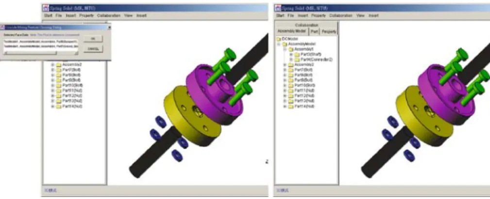
Consider, for example, the engineering change of a shaft coupling. Figure7presents the assembling operation which can be performed collaboratively over the Internet.
En-gineers can share ideas and discuss the three-dimensional model to be changed interactively. The user interface presents the three-dimensional models with parts, geometry and information about its features. A user can change the shape of a part by selecting and modifying its parameters. When an engineering change must be made to a bolt, changing its size from M5 to M8, the changed part with the new parameter is entered into the PDM system. An en-gineering change notification, generated by the PDM system, is issued and passed to the relevant users. The en-gineering change propagation system proposed herein helps to identity and list all the affected items. The first affected item, or the feature next to the changed item, must also be changed by shifting its diameter from 5 to 8 mm. This information is then passed to the CAD module to verify the size of the feature. The same operations are applied to all the affected items in order. Figure8shows the final assembly model after all the engineering changes have been made.
6 Conclusion
This investigation focuses on the architecture of a col-laborative design for an assembly to build a structure for exchanging information instantaneously over Internet/In-tranet about the related engineering changes. The advan-tages of the scheme are as follows:
1. This work emphasizes the web-based collaborative system by which designers from a range of enterprises can coordinate changes with each other.
2. The kernel in the server tier performs the complicated computing and manages the section for reducing the loading of the client tier. It also improves the security of the system kernel and the information of the enterprise.
3. The intelligent server can manage the section data so that information can be exchanged systemically and effectively.
4. The function of the data tier is similar to that of an electronic coffer. It ensures the security of the enterprise’s knowledge and product information. Propagating design change is an important part of col-laborative engineering. The spreading time directly affects the product’s life cycle. This work provides a method for
Fig. 7 Collaborative design of the assemble model
Fig. 8 Results of the design change propagation
propagating these changes which provides the following advantages:
1. It propagates the design changes immediately and ac-curately. This work takes into consideration the process and relevant rules by which design information is distributed.
2. It saves the high-level feature data under mating con-ditions in order to maintain the geometric changes and to instantly modify the corresponding features. 3. The initialization of the assembly model improves the
affectivity of the search and increases the speed of the entire propagating process.
4. It maintains the correctness and feasibility of the dis-tributed data in the propagating process by updating design-change items instantaneously.
References
1. Huang GQ, Mak KL (2002) Design for manufacture and assembly on the Internet. Comput Indus 38:17–30
2. Shyamsundar N, Gadh R (2001) Internet-based collaborative product design with assembly features and virtual design spaces. Comput Aided Des 33:637–651
3. Noort A, Hoek GFM, Bronsvoort WF (2002) Integrating part and assembly modeling. Comput Aided Des 34:899–912 4. Mascle C (2002) Feature-based assembly model for integration
in computer-aided assembly. Robot Comput Integr Manuf 18 (5–6):373–378
5. Sung CW (2001) Automatic assembly feature recognition and dis-assembly sequence generation. PhD Thesis, Heriot-Watt University, Edinburgh
6. You CF, Yeh SC (2002) Engineering change propagation system using STEP. Concurrent Eng Res Appl 10(4):349–356 7. Java Shared Data Toolkit JSDT API 2.0, Sun Microsystem Inc.,