OFDM RF power-fading circumvention for
long-reach WDM-PON
C. W. Chow,1,* C. H. Yeh,2 and J. Y. Sung1
1Department of Photonics and Institute of Electro-Optical Engineering, National Chiao Tung University, Hsinchu 30010, Taiwan
2 Department of Photonics, Feng Chia University, Seatwen, Taichung 40724, Taiwan *[email protected]
Abstract: We propose and demonstrate an orthogonal frequency division multiplexing (OFDM) radio-frequency (RF) power-fading circumvention scheme for long-reach wavelength-division-multiplexed passive-optical-network (LR-WDM-PON); hence the same capacity of 40 Gb/s can be provided to all the optical-networking-units (ONUs) in the LR-WDM-PON. Numerical analysis and proof-of-concept experiment are performed. ©2014 Optical Society of America
OCIS codes: (060.2330) Fiber optics communications; (060.4510) Optical communications. References and links
1. P. D. Townsend, G. Talli, C. W. Chow, E. M. MacHale, C. Antony, R. Davey, T. De Ridder, X. Z. Qiu, P. Ossieur, H. G. Krimmel, D. W. Smith, I. Lealman, A. Poustie, S. Randel, and H. Rohde, “Long reach passive optical networks,” IEEE LEOS Annual Meeting, 2007, Invited Paper, Florida, USA.
2. Z. Xu, Y. J. Wen, W.-D. Zhong, M. Attygalle, X. Cheng, Y. Wang, T. H. Cheng, and C. Lu, “WDM-PON architectures with a single shared interferometric filter for carrier-reuse upstream transmission,” J. Lightwave Technol. 25(12), 3669–3677 (2007).
3. A. Chowdhury, H. C. Chien, M. F. Huang, and J. Yu, “Rayleigh backscattering noise-eliminated 115-km long-reach bidirectional centralized WDM-PON with 10-Gb/s DPSK downstream and remodulated 2.5-Gb/s OCS-SCM upstream signal,” IEEE Photon. Technol. Lett. 20(24), 2081–2083 (2008).
4. C. W. Chow, G. Talli, A. D. Ellis, and P. D. Townsend, “Rayleigh noise mitigation in DWDM LR-PONs using carrier suppressed subcarrier-amplitude modulated phase shift keying,” Opt. Express 16(3), 1860–1866 (2008). 5. C. H. Chang, W. Y. Lin, H. H. Lu, C. Y. Chen, P. Y. Wu, and Y. P. Lin, “An integrated long-reach PON and
GI-POF in-house network architecture for hybrid CATV/OFDM signals transmission,” J. Lightwave Technol. 30(20), 3247–3251 (2012).
6. J. Ma, J. Yu, C. Yu, X. Xin, J. Zeng, and L. Chen, “Fiber dispersion influence on transmission of the optical millimeter-waves generated using LN-MZM intensity modulation,” J. Lightwave Technol. 25(11), 3244–3256 (2007).
7. H. C. Chien, A. Chowdhury, Z. Jia, Y. T. Hsueh, and G. K. Chang, “60 GHz millimeter-wave gigabit wireless services over long-reach passive optical network using remote signal regeneration and upconversion,” Opt. Express 17(5), 3016–3041 (2009).
8. C. W. Chow, C. H. Yeh, C. H. Wang, F. Y. Shih, C. L. Pan, and S. Chi, “WDM extended reach passive optical networks using OFDM-QAM,” Opt. Express 16(16), 12096–12101 (2008).
9. X. Xin, L. Zhang, B. Liu, and J. Yu, “Dynamic λ-OFDMA with selective multicast overlaid,” Opt. Express 19(8), 7847–7855 (2011).
10. D. Qian, S. H. Fan, N. Cvijetic, J. Hu, and T. Wang, “64/32/16 QAM-OFDM using direct-detection for 40G-OFDMA-PON downstream,” Prof. of OFC, 2011, Paper OMG4.
11. J. Y. Sung, K. T. Cheng, C. W. Chow, C. H. Yeh, and C.-L. Pan, “A scalable and continuous-upgradable optical wireless and wired convergent access network,” Opt. Express 22(11), 12779–12784 (2014).
12. D. Z. Hsu, C. C. Wei, H. Y. Chen, W. Y. Li, and J. Chen, “Cost-effective 33-Gbps intensity modulation direct detection multi-band OFDM LR-PON system employing a 10-GHz-based transceiver,” Opt. Express 19(18), 17546–17556 (2011).
13. C. H. Yeh, C. W. Chow, H. Y. Chen, and B. W. Chen, “Using adaptive four-band OFDM modulation with 40 Gb/s downstream and 10 Gb/s upstream signals for next generation long-reach PON,” Opt. Express 19(27), 26150–26160 (2011).
14. T. Jiang and Y. Wu, “An overview: peak-to-average power ratio reduction techniques for OFDM signals,” IEEE Trans. Broadcast 54(2), 257–268 (2008).
1. Introduction
Passive optical networks (PONs) have been deployed in many places. In order to support more and more users, possible solutions are to extend the reach of present PONs [1] and use
wavelength division multiplexing (WDM) [2]. Hence, the ideas of WDM extended-reach (ER)-PON (~40 km) and WDM long-reach (LR)-PON (> 60 km) have been proposed and demonstrated [3–5]. These ER-PON and LR-PON should provide 40 Gb/s for each optical networking unit (ONU). Transmitting a high data rate of 40 Gb/s signal in an optical fiber can result in severe dispersion-induced radio-frequency (RF) power fading [6, 7]. Spectral efficient modulation format, such as orthogonal frequency division multiplexing (OFDM) can reduce the dispersion-induced RF power fading owing to the compact OFDM spectrum [8, 9]. Recently, 40 Gb/s OFDM PON has been demonstrated at standard reach (~20 km) [10]; however, the issue of RF power fading still happens in ER-PON or LR-PON. Up to now, the most effective scheme to mitigate the influence of RF power fading is to use adaptive bit-loading in the OFDM signal [11]. Higher level modulation formats can be applied to frequency band with higher signal-to-noise ratio (SNR). However, data cannot be applied to the intensity nulls appeared at the frequency spectrum; hence this limits the capacities of the ONUs [12]. has proposed an OFDM LR-PON, in which different OFDM frequency-bands can be switched-off (called the “forbidden-band”) depending on the fiber lengths between the optical line terminal (OLT) and different ONUs. This means that the near ONUs and remote ONUs should switch-off different OFDM frequency-bands in order to avoid the spectral intensity nulls due to RF power fading. However, this will reduce the transmission capacity of different ONUs, and complicated frequency planning of the OFDM “forbidden-band” is needed.
In this work, we propose and demonstrate an OFDM RF power-fading circumvention scheme for LR-WDM-PON; hence the same capacity of 40 Gb/s can be provided to all the ONUs in the LR-PON. As a result, switching-off different frequency-bands (forbidden-band) as reported in [12] is not required. In our demonstration, the same level of modulation is applied to each OFDM subcarrier; hence bit-loading scheme is not necessary. Numerical analysis of the proposed scheme under different fiber transmissions is studied. Proof-of-concept experimental demonstration is also performed. Results show that the OFDM RF power fading effect can be significantly circumvented without scarifying the OFDM spectrum.
2. Proposed architecture and numerical analysis
Figure 1 shows the proposed architecture of the OFDM RF power-fading circumvention scheme. Here, only the downlink of the network is discussed. Usually the uplink data rate is lower than the downlink data rate; hence the RF power fading in uplink signal may not be significant. If 40 Gb/s symmetric network is required, the proposed scheme could also be applied in the uplink signal. In the OLT, a continuous-wave (CW) laser is launched to a Mach-Zehnder modulator (MZM) which is biased at null and electrical driven at 20 GHz sinusoidal signal; hence an optical carrier suppressed (OCS) signal is produced. The 40 GHz apart optical two tones of the OCS are wavelength separated by an optical red/blue filter (RBF); then each tone is launched into an optical modulator (MOD). The electrical OFDM signal produced by the OFDM generator is divided into two copies, and they are applied to the two MODs with the opposite alpha chirp parameters of + 1 and −1 simultaneously as shown in Fig. 1. The electrical bandwidths of the two MODs are 10 GHz. In the OFDM generator, in order to generate 40 Gb/s OFDM data, high-speed 10 GHz bandwidth electronic analog-to-digit and digit-to-analog converters (ADC/DAC) are required if 16 quadrature-amplitude-modulation (QAM) is used. The 10 GHz bandwidth ADC/DAC is not available in our laboratory; hence in the experiment, we use a four-band OFDM signals generated by two sets of arbitrary wavelength generators (AWGs) to provide the aggregated data rate of 40 Gb/s. The four-band OFDM generation is similar to the scheme described in [13].
As shown in the inset of Fig. 1, band 1 OFDM consists of 40 OFDM subcarriers occupying bandwidth of 1.5625 GHz to produce a data rate of 6.25 Gb/s. Band 2 to 4 are upconverted to frequencies of 3.1641 GHz, 6.0547 GHz and 8.9453 GHz by using I–Q modulation, respectively. In band 2 to 4, each band consists of 72 subcarriers (excluding the local oscillator carrier at the center of each band), occupying bandwidth of 2.8124 GHz to
produce a data rate of 11.2496 Gb/s. Hence, a total data rate of 39.9988 Gb/s ( = ~40 Gb/s) is obtained. In the experiment, band 1 OFDM is generated by AWG1, while band 2 to 4 OFDM are generated by AWG2. Three 4-port IQ mixers from Hittite are used for the band 2 to 4 frequency upconversion. The four-band OFDM signals use the same modulation of 16-QAM with a total fast-Fourier transform (FFT) size of 512 and cyclic prefix (CP) size of 8. By excluding the CP, the net data rate is 38.7488 Gb/s. The OFDM generation consists of serial-to-parallel (S/P) conversion, QAM symbol encoding, inverse fast Fourier transform (IFFT), CP insertion, and DAC. The DAC used is the AWG. Then the identical 40 Gb/s optical OFDM signals carried by the optical two tones with alpha chirp parameters of + 1 and −1 are transmitted in different length of standard single mode fiber (SMF) to emulate different ONU transmission distances. In each ONU, the two optical tones are wavelength separated and directly detected by PIN photodiodes (PDs), which are connected to the OFDM detector. In the OFDM detector, the received electrical four-band OFDM signals are separated, down-converted and captured by using off-line Matlab programs. The demodulation process includes the synchronization, FFT, one-tap equalization, and QAM decoding. Finally, the bit error rate (BER) is obtained according to the measured SNR of each OFDM subcarrier.
OLT Rx Laser ONU Optical amplifier SMF PD PD MODA MODB OFDM Generator Op tic al MU X O FDM Detec to r ONU ONU Op ti ca l MU X OCS Band 2
Band1 Band 3 Band 4
GHz 0.8789 3.1641 6.0547 8.9453
1.5625 2.8124 2.8124 2.8124
Fig. 1. Proposed architecture of OFDM RF power-fading circumvention scheme for LR-WDM-PON. OCS: optical carrier suppress signal; MOD: modulator; SMF: single mode fiber; PD: photodiode. Inset: schematic spectrum of the 4 OFDM bands.
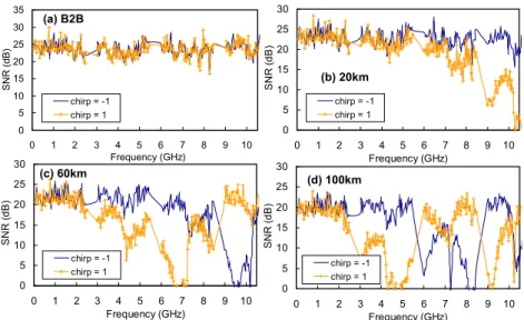
When the optical signal is propagating in an optical fiber, fiber chromatic dispersion causes a differential delay to be progressively added to the sidebands and the carrier; hence this results in spectral intensity nulls, called RF power fading in the received signal. Numerical analysis of the dispersion-induced RF power fading at different SMF transmissions is performed by using VPI Transmission Maker V.7.5. The signal used in the simulation is the 4-band OFDM signal described in last paragraph. Figures 2(a)-2(d) shows the simulated dispersion-induced RF power fading effects. We can observe that there is no RF power fading null at back-to-back (B2B) as shown in Fig. 2(a), and the null shift to lower frequencies when fiber transmission increases as shown in Fig. 2(b) and 2(c), and the number of nulls will increase in the spectrum. As shown in Fig. 2(c), the RF power fading nulls occur at 10 GHz and 7 GHz when the −1 chirped and + 1 chirped MODs are used respectively. When the transmission distance increases to 100 km, the RF power fading nulls occur at 6, 8 and 10 GHz when using −1 chirped MOD; and the RF power fading nulls occur at 5, 7 and 9 GHz when using + 1 chirped MOD, as shown in Fig. 2(d). As shown in Fig. 2(b)-2(d), we can observe that the RF power fading nulls occur at different frequency bands when the + 1 and −1 chirped MODs are used, then the Media Access Control (MAC) layer at the ONU can select the OFDM subcarriers with higher SNR and restore the transmission performance. Figures 3(a)-3(d) show the corresponding calculated BER based on the SNR analysis shown in Fig. 2(a)-2(d) respectively. As shown in Figs. 3(c) and 3(d), if only one MOD is used, the BER cannot satisfy the forward error correction (FEC) requirement.
0 5 10 15 20 25 30 0 1 2 3 4 5 6 7 8 9 10 Frequency (GHz) SN R ( d B) chirp = -1 chirp = 1 0 5 10 15 20 25 30 35 0 1 2 3 4 5 6 7 8 9 10 Frequency (GHz) SNR ( d B ) chirp = -1 chirp = 1 0 5 10 15 20 25 30 0 1 2 3 4 5 6 7 8 9 10 Frequency (GHz) SN R ( d B) chirp = -1 chirp = 1 (a) B2B (b) 20km (c) 60km (d) 100km 0 5 10 15 20 25 30 0 1 2 3 4 5 6 7 8 9 10 Frequency (GHz) SN R ( d B ) chirp = -1 chirp = 1
Fig. 2. Simulated dispersion-induced RF power fading effects under different SMF transmissions when using −1 and + 1 chirped MODs.
-3.5 -3 -2.5 -2 -1.5 -1 -0.5 0 -32 -30 -28 -26 -24 -22 -20 -18 -16 -14 -12 Received optical power (dBm)
Log ( B E R ) chirp = -1 chirp = +1 proposed -5.5-5 -4.5-4 -3.5-3 -2.5-2 -1.5-1 -0.50 -26 -24 -22 -20 -18 -16 -14 -12 -10 -8 Received optical power (dBm)
Log ( B E R ) chirp = -1 chirp = +1 proposed -5 -4.5-4 -3.5-3 -2.5-2 -1.5-1 -0.50 -28 -26 -24 -22 -20 -18 -16 -14 -12 -10 -8 Received optical power (dBm)
Log ( B E R ) chirp = -1 chirp = +1 proposed -3.5 -3 -2.5 -2 -1.5 -1 -0.5 0 -30 -28 -26 -24 -22 -20 -18 -16 -14 -12 -10 Received optical power (dBm)
Log ( B E R ) chirp = -1 chirp = +1 proposed (a) B2B (b) 20km (c) 60km (d) 100km
Fig. 3. BER based on the SNR analysis under different SMF transmissions when using −1, + 1 chirped MODs and the proposed scheme.
-19 -18 -17 -16 -15 -14 0 5 10 15 20 25 30 35 40 45 0 10 20 30 40 50 60 70 80 90 100 R x s ens itiv ity (dBm ) Bit -rat e (Gb/ s) Fiber length (km) 15 16 17 18 19 20 21 22 23 24 25 0 5 10 15 20 25 30 35 40 45 0 10 20 30 40 50 60 70 80 90 100 Av e SN R (dB) Bi t-rat e (Gb/ s) Fiber length (km) (a) (b)
Fig. 4. (a) Total data rate and Rx sensitivity, (b) total data rate and average SNR of the proposed scheme at different SMF transmissions.
Figure 4(a) and 4(b) show the total data rate, the corresponding Rx sensitivity and the corresponding average SNR of the proposed scheme at different SMF transmissions respectively. Although the Rx sensitivity at FEC and the average SNR degrade when the fiber length increases, the same 40 Gb/s data rate can be achieved by all the ONUs.
3. Experiment results and discussion
The experiment based on the architecture shown in Fig. 1 is performed. Due to the unavailable of the exact −1 and + 1 chirped MODs, we commercially obtain the two MZMs with + 0.53 chirp and −0.7 chirp parameters (according to the specifications). In order to test whether the two chirped MZMs have similar behavior as our analysis in Section 2, we measure the received SNR at B2B and after 20 km SMF using the two MZMs. The 40 Gb/s OFDM experimental generation and detection are described in last section. 5 GS/s sampling rate is used in each OFDM band with 8-bit resolution. OFDM signal has a high peak-to-average power ratio (PAPR), and the system performance will be degraded if non-linear components are presented [14]. The spurious free dynamic range (SFDR) is > 35 dB by proper DC-biasing the MZM with the modulator driver. In this proof-of-concept experiment, two distributed feedback lasers (DFB-LDs) with wavelengths of 1550 nm and 1550.8 nm are used instead of the OCS. The use of two wavelengths may reduce the number of channels in the WDM-PON and increase the complexity as two OFDM signals have to be processed; however, much higher capacity can be assigned to different ONUs. Besides, we can also make use of the free spectral range (FSR) property of the optical multiplexer (MUX), and select the two wavelengths which are one FSR apart.
Figures 5(a) and 5(b) show the measured SNR of each OFDM subcarrier at the B2B and 20 km SMF fiber transmission using the two MZMs. No RF power fading effect is observed at B2B in both cases. After 20 km, the measured SNRs drop from 8 GHz to 10 GHz, and the SNR is the worst at around 10 GHz region as shown in Fig. 5(a). The reduction of experimental SNR shows similar behavior when compared with the simulated RF power fading using + 1 chirped MOD shown in Fig. 2(b). As shown in Fig. 5(a), the average SNR cannot achieve FEC requirement (SNR = 16.5 dB at BER = 3.8 x 10⁻³), when the OFDM subcarrier frequency is > 7.2 GHz. Therefore, the total data rate cannot achieve 40 Gb/s in 20 km SMF transmission due to the worse SNR in nearly one third of the OFDM spectrum. Fig. 5(b) shows the measured SNR when the −0.7 chirped MZM is used. The frequency response is relatively flat for the whole frequency range. The experimental SNR shows similar behavior when compared with the simulated RF power fading using −1 chirped MOD shown in Fig. 2(b). The measured SNRs of nearly all the OFDM bands are higher than FEC requirement; hence the total data rate of 40 Gb/s can be provided to the ONU using the −0.7 chirped MZM. 0 5 10 15 20 25 30 0 1 2 3 4 5 6 7 8 9 10 Frequency (GHz) S NR ( d B) 0 5 10 15 20 25 30 0 1 2 3 4 5 6 7 8 9 10 Frequency (GHz) SN R ( d B) (a) +0.53 chirped MZM B2B 20km SMF (b) -0.7 chirped MZM B2B 20km SMF
Fig. 5. SNR of the OFDM subcarriers at B2B and after 20 km SMF when using (a) + 0.53 chirped MZM and (b) −0.7 chirped MZM.
In the ONU, the signals received by the 2 PDs (2 different wavelengths) are demodulated and analyzed. At each subcarrier frequency, the 2 signals are compared and the higher SNR
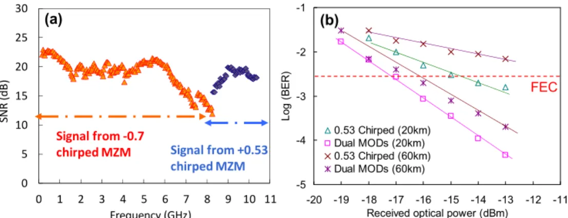
value is selected. The compare-and-select function can be built in the ONU-MAC. Hence a spectrum of higher SNR against subcarrier frequency can be obtained. For example, Fig. 6(a) shows the spectrum of the higher SNR against subcarrier frequency after 60 km of SMF. At lower frequency subcarriers, higher SNR signals are obtained from the −0.7 chirped MZM (in orange color); and at higher frequency subcarriers, the higher SNR signals are obtained from the + 0.53 chirped MZM (in purple color). Finally, the average SNR is 19.18 dB.
Finally, BER is obtained according to the SNR of each OFDM subcarrier in different scenarios described above. As shown in Fig. 6(b), the proposed scheme can achieve the BER below the FEC limit in 20 km and 60 km transmissions without sacrificing the capacity, while using a single MZM cannot.
0 5 10 15 20 25 30 0 1 2 3 4 5 6 7 8 9 10 11 SNR (d B ) Frequency (GHz) Signal from -0.7
chirped MZM Signal from +0.53
chirped MZM -5 -4 -3 -2 -1 -20 -19 -18 -17 -16 -15 -14 -13 -12 -11
Received optical power (dBm)
Lo g ( B E R ) 0.53 Chirped (20km) Dual MODs (20km) 0.53 Chirped (60km) Dual MODs (60km) FEC (a) (b)
Fig. 6. (a) Spectrum of the higher SNR against subcarrier frequency after 60 km, (b) BER of using a single + 0.53 chirped modulator and the proposed scheme using two chirped modulators.
4. Conclusion
RF power fading is one of the critical issues in 40 Gb/s OFDM ER-PON and LR-PON. Up to now, schemes such as adaptive bit-loading and the use of “forbidden-band” depending on different fiber transmission lengths have their limitations. In this work, we proposed and demonstrated an OFDM RF power-fading circumvention scheme for LR-WDM-PON. The same capacity of 40 Gb/s can be provided to all the ONUs in the LR-PON. Here, only the downlink of the network was discussed. If 40 Gb/s symmetric network is required, the proposed scheme could also be applied in the uplink signal. Numerical analysis of the proposed scheme was performed. In the proof-of-concept demonstration, MZMs with + 0.53 chirp and −0.7 chirp parameters were used. Besides, the same level of modulation (16-QAM) can be used in all the OFDM subcarriers. Experimental results showed that significant RF power fading effect can be circumvented without scarifying the OFDM spectrum.
Acknowledgments
This work was supported by Ministry of Science and Technology, Taiwan, ROC, MOST-103-2221-E-009-030-MY3, MOST-101-2628-E-009-007-MY3, Aim for the Top University Plan, Taiwan, and Ministry of Education, Taiwan.