Low efficiency droop in blue-green m-plane InGaN/GaN light emitting diodes
Shih-Chun Ling, Tien-Chang Lu, Shih-Pang Chang, Jun-Rong Chen, Hao-Chung Kuo, and Shing-Chung Wang
Citation: Applied Physics Letters 96, 231101 (2010); doi: 10.1063/1.3449557
View online: http://dx.doi.org/10.1063/1.3449557
View Table of Contents: http://scitation.aip.org/content/aip/journal/apl/96/23?ver=pdfcov Published by the AIP Publishing
Articles you may be interested in
Size-dependent efficiency and efficiency droop of blue InGaN micro-light emitting diodes Appl. Phys. Lett. 101, 231110 (2012); 10.1063/1.4769835
Efficiency and droop improvement in green InGaN/GaN light-emitting diodes on GaN nanorods template with SiO2 nanomasks
Appl. Phys. Lett. 101, 233104 (2012); 10.1063/1.4768950
Raman and emission characteristics of a-plane InGaN/GaN blue-green light emitting diodes on r-sapphire substrates
J. Appl. Phys. 109, 043103 (2011); 10.1063/1.3549160
Understanding efficiency droop effect in InGaN/GaN multiple-quantum-well blue light-emitting diodes with different degree of carrier localization
Appl. Phys. Lett. 97, 201112 (2010); 10.1063/1.3520139
Efficiency droop alleviation in InGaN/GaN light-emitting diodes by graded-thickness multiple quantum wells Appl. Phys. Lett. 97, 181101 (2010); 10.1063/1.3507891
This article is copyrighted as indicated in the article. Reuse of AIP content is subject to the terms at: http://scitation.aip.org/termsconditions. Downloaded to IP: 140.113.38.11 On: Wed, 30 Apr 2014 10:16:05
Low efficiency droop in blue-green m-plane InGaN/GaN light
emitting diodes
Shih-Chun Ling,1Tien-Chang Lu,1,2,a兲Shih-Pang Chang,1,3Jun-Rong Chen,1 Hao-Chung Kuo,1,a兲 and Shing-Chung Wang1
1
Department of Photonics, Institute of Electro-Optical Engineering, National Chiao Tung University, Hsinchu 300, Taiwan
2
Institute of Lighting and Energy Photonics, National Chiao Tung University, Tainan 711, Taiwan 3
R&D Division, Epistar Co. Ltd., Science-based Industrial Park, Hsinchu 300, Taiwan 共Received 15 April 2010; accepted 17 May 2010; published online 7 June 2010兲
We investigated the electroluminescence and relatively external quantum efficiency 共EQE兲 of m-plane InGaN/GaN light emitting diodes 共LEDs兲 emitting at 480 nm to elucidate the droop behaviors in nitride-based LEDs. With increasing the injection current density to 100 A/cm2, the m-plane LEDs exhibit only 13% efficiency droop, whereas conventional c-plane LEDs suffer from efficiency droop at very low injection current density and the EQE of c-plane LEDs decrease to as little as 50% of its maximum value. Our simulation models show that in m-plane LEDs the absence of polarization fields manifest not only the hole distribution more uniform among the wells but also the reduction in electron overflow out of electron blocking layer. These results suggest that the nonuniform distribution of holes and electron leakage current due to strong polarization fields are responsible for the relatively significant efficiency droop of conventional c-plane LEDs. © 2010 American Institute of Physics. 关doi:10.1063/1.3449557兴
In the state-of-art c-plane InGaN/GaN multiple-quantum-well 共MQW兲 light-emitting diodes 共LEDs兲, the quantum efficiency reaches its peak at very low current density, typically⬍10 A/cm2, and monotonically decreases with further increasing drive current, which is the critical
restriction for the usage of LEDs in high power
application.1,2 This phenomenon, well known as efficiency droop, becomes more severe while the peak emission wave-length of LEDs further increases from UV spectral range toward blue and green spectral range.3 Even though driving the blue/green LEDs under short and low-duty cycle pulses to minimize the self-heating effect, the droop in quantum efficiency remains nearly identical.3 Various methods are proposed to mitigate the efficiency droop, including quater-nary AlInGaN barriers that eliminate electron overflow,4,5 thick active region of double heterostructure that reduce Au-ger nonradiative recombination rate,6,7 reduction in barrier thickness that makes hole distribution more uniform among the wells,8 and so on. Nonpolar 关11¯00兴 m-plane epitaxial orientation has been demonstrated to increase internal quan-tum efficiency in LEDs because of the absence of polariza-tion fields.9–11The usage of nonpolar orientation in LEDs is
also expected to reduce the electron overflow and enhance holes transport throughout the active region, once again ow-ing to the absence of polarization fields, and therefore miti-gation of efficiency droop is predicted. Recently, Li et al.11 reported that the near UV 共⬃400 nm兲 m-plane LEDs can achieve efficiency retention even at high current injection level. Nevertheless, an overall physical explanation for effi-ciency retention of m-plane LEDs is still absent. Moreover, the behavior of efficiency droop of m-plane LEDs in blue-green emission wavelength range has not yet been reported, where the conventional c-plane LEDs suffer a more signifi-cant drop in quantum efficiency at high injection current den-sity. In this paper, we present the comparison of efficiency droop in c-plane and m-plane LEDs with 480 nm emission wavelength and, for the exploration of origin of efficiency droop, the carrier injection and distribution in the polar c-plane and nonpolar m-plane active region are investigated numerically by the advanced physical models of semicon-ductor devices 共APSYS兲 simulation program, which was
de-veloped by the Crosslight Software Inc.12
The respective c-plane and m-plane LED structures in-vestigated are grown on c-plane GaN templates on sapphire
a兲Electronic addresses: timtclu@mail.nctu.edu.tw and hckuo@mail.nctu.edu.tw.
0 20 40 60 80 100 120 0 2 4 1KHz, 0.1% c-plane LED
Current density (A/cm2)
Li g h t int e n sity (a.u. ) 0 20 40 60 80 100 N o rm alize d E Q E (% ) 0 20 40 60 80 100 120 0 2 4 1KHz, 0.1% m-plane LED
Current density (A/cm2)
Li gh t intens it y (a .u. ) 0 20 40 60 80 100 N o rm a liz e d E Q E (% )
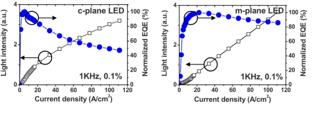
FIG. 1. 共Color online兲 Integrated EL intensity and normalized EQE as a function of forward current density for c-plane LED and m-plane LED, re-spectively. Both samples have the same MQW active region and EBL structure.
APPLIED PHYSICS LETTERS 96, 231101共2010兲
0003-6951/2010/96共23兲/231101/3/$30.00 96, 231101-1 © 2010 American Institute of Physics
This article is copyrighted as indicated in the article. Reuse of AIP content is subject to the terms at: http://scitation.aip.org/termsconditions. Downloaded to IP: 140.113.38.11 On: Wed, 30 Apr 2014 10:16:05
and on m-plane bulk substrates using the low pressure met-alorganic chemical vapor deposition system. Both they com-prises a 2-m-thick undoped GaN layer, followed by a 2-m-thick n-type GaN layer with an electron concentration of 3⫻1018 cm−3. Then a six-period InGaN/GaN MQW ac-tive region is grown, consisting of 2.7-nm-thick In0.22Ga0.78N wells and 11-nm-thick GaN barriers. On top of the active region is 20-nm-thick p-Al0.1Ga0.9N electron blocking layer 共EBL兲 and 0.2-m-thick p-type GaN capping layer with a hole concentration of 1⫻1018 cm−3. Subsequently, 300 ⫻300 m2diode mesas are defined by chlorine-based reac-tive ion etching. Indium-tin-oxide共230 nm兲 layer is used as the transparent p-contact and finally Cr/Au共100/200 nm兲 are deposited to be the p-GaN and n-GaN contact pads. The EL measurements are performed in an unencapsulated wafer form, in which light output are collected primarily on-axis into the integrating sphere with a Si photodetector. Devices are tested in pulsed mode with 1 KHz frequency and 0.1% duty cycle to prevent self-heating effect. The EL spectra showed the center wavelength for both reference c-plane LEDs and m-plane LEDs is around 480 nm.
Figure1shows the light output intensity and normalized external quantum efficiency共EQE兲 as a function of forward current density for c-plane LED and m-plane LED, respec-tively. The light output-current curve of the reference c-plane LED is linear at low current density but becomes sublinear at high current density, indicating a reduced EQE. Its peak ef-ficiency occurs at⬃5 A/cm2. Over this peak efficiency, the efficiency decreases rapidly. When the current density ex-ceeds 100 A/cm2, the EQE is reduced to just 50% of its maximum value. In contrast, the m-plane LED exhibits only 13% efficiency droop with increasing the injection current density to 100 A/cm2, which shows almost negligible droop. It is also noticeable that the characteristic current density, which marks the peak efficiency, is extended to ⬃23 A/cm2.
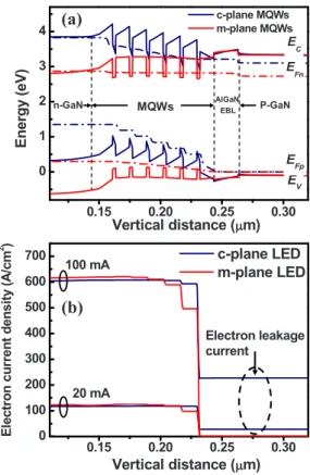
For the exploration of physical origin of efficiency droop in InGaN/GaN LEDs, we performed the simulation of afore-mentioned polar c-plane and nonpolar m-plane LED struc-ture using the APSYS simulation software. Commonly ac-cepted parameters are used in the simulations, including a Shockley–Read–Hall recombination lifetime of 1 ns, an Au-ger recombination coefficient of 2⫻10−30 cm6s−1, and total polarization charge densities of 8.3⫻1012 cm−2 at the inter-faces between the wells and barriers in the active region, respectively. Figure 2共a兲shows the calculated energy band diagram of the reference c-plane and m-plane LED at a for-ward current of 20 mA. For the c-plane LED, as a result of the polarization charges, a severe situation of band bending, i.e., sloped triangular barriers and wells, is observed. Fur-thermore, the conduction band slopes upward while it
ap-proaches to the MQW active region from the n-GaN side and consequently the conduction band close to n-GaN is higher than the conduction band close to p-GaN, which results in a large electron leakage current. Even though an AlGaN EBL is introduced, the electron current overflows out of the MQW region even at a low current of 20 mA. With increasing the forward current to 100 mA, the electron leakage becomes more severe, as shown in Fig. 2共b兲. The electrons escaped from MQW active region are not contributed to radiative recombination and thereby lower the LED efficiency. This reveals the electron leakage current due to polarization fields is one of the dominated mechanisms that results in efficiency droop. In the m-plane LED, because of the absence of polar-ization fields, its GaN barriers do not exhibit triangular shape and the conduction band near p-GaN side is now higher than that near n-GaN side. As a result, the electron leakage current as well as efficiency droop is reduced significantly.
Figure 3 shows the carrier distribution in the whole InGaN/GaN MQWs structure at 20 mA forward current for the m-plane LED and the c-plane LED. It is obvious that in
0.15 0.20 0.25 0.30 0 100 200 300 400 500 600 700 Electron leakage current 100 mA 20 mA c-plane LED m-plane LED El e c tr o n c ur re nt de ns it y (A /c m 2 ) Vertical distance (μμm) MQWs n-GaN AlGaN EBL P-GaN 0.15 0.20 0.25 0.30 0 1 2 3 4 EV EFp EFn EC c-plane MQWs m-plane MQWs Energy (eV) Vertical distance (μμm)
(a)
(b)
FIG. 2. 共Color online兲 共a兲 Calculated band diagram of m-plane LED and reference c-plane LED under forward bias operation.共b兲 Simulated electron current density throughout the whole m-plane LED structure as well as c-plane LED structure at 20 and 100 mA forward current.
0.15 0.20 0.25 0.30 16 18 20 Electron Hole Carrier co ncen tr at ion (l og) (1/ cm 3 ) Vertical distance (μμm) 0.15 0.20 0.25 0.30 16 18 20 Electron Hole Car rier concent ra ti on (l og) (1/cm 3 ) Vertical distance (μμm) m-LED
(a)
(b)
c-LEDFIG. 3.共Color online兲 Distribution of carrier concentration of InGaN/GaN MQWs structure at 20 mA forward current density for共a兲 m-plane LED and共b兲 c-plane LED.
231101-2 Ling et al. Appl. Phys. Lett. 96, 231101共2010兲
This article is copyrighted as indicated in the article. Reuse of AIP content is subject to the terms at: http://scitation.aip.org/termsconditions. Downloaded to IP: 140.113.38.11 On: Wed, 30 Apr 2014 10:16:05
the c-plane LED both electrons and holes distributions are quite nonuniform among the quantum wells especially for holes. This is because holes have a relatively larger effective mass and therefore a very low mobility. Moreover, the trian-gular potential barriers which result from polarization fields hinder the holes transport throughout the active region as well. Under these circumstances, a large amount of minority carrier holes accumulate in the last well next to the p-GaN side, which means only the last quantum well next to p-GaN contributes to radiative recombination in the c-plane LED. It results in two circumstances. One is inefficient recombina-tion with electrons in the other five wells increases the excess electron density and thus enhances the electron leakage. Sec-ond is the higher carrier density accumulated in the last well of c-plane LEDs, as compared with the m-plane LEDs, causes the greater radiative recombination rate relative to the nonradiative recombination rate, which is responsible for that the c-plane LEDs reach maximum efficiency at much lower current density than the m-plane LEDs do. In addition, in a recent paper, Shen and co-workers demonstrate that the Auger recombination coefficient is ⬃2⫻10−30 cm6s−1 rather than a previous accepted value of 1⫻10−34 cm6s−1.6 which is large enough to significantly decrease the internal quantum efficiency of InGaN/GaN MQW LEDs at their stan-dard operating currents. Since the carrier density accumu-lated in the c-plane MQWs is larger than that in the m-plane MQWs at the same forward current, it is expected that the Auger recombination rate in the c-plane LED is higher. The Auger coefficient in m-plane GaN has not yet been reported, we assume that Auger coefficient is also 2⫻10−30 cm6s−1 for m-plane orientation. In our calculation, at 20 mA forward current, the Auger recombination rate of the c-plane LED is 1.4⫻1027 cm−3s−1, which is approximately twice higher than that of m-plane LED共⬃8⫻1026 cm−3s−1兲 and thereby causes more severe efficiency droop.
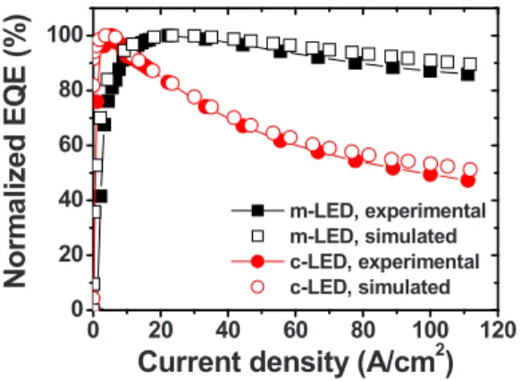
After considering three aforementioned droop factors 关including 共1兲 electron leakage 共2兲 hole transport and injec-tion efficiency 共3兲 Auger recombination兴, we simulated the EQE droop for c-plane LEDs and m-plane LEDs. The simu-lated and experimental EQE as a function of forward current density for c-plane LEDs and m-plane LEDs is plotted in Fig.4, which shows good agreement between the experimen-tal data and our simulation. It suggests that strongly inherent polarization fields are responsible for the significant effi-ciency droop of c-plane LEDs. Contrary to the c-plane LED, the m-plane LED exhibits the efficiency retention at high current injection as a result of the absence of polarization fields.
In conclusion, we have demonstrated relatively low effi-ciency droop in blue-green m-plane InGaN/GaN LEDs as compared with the c-plane LEDs. The EQE is nearly retained in m-plane LEDs even at a high forward current density of 100 A/cm2 共only 13% droop兲, whereas c-plane LEDs
ex-hibit as high as 50% efficiency droop under the same injec-tion current density. Our theoretical simulainjec-tions reveal that the strong polarization fields in the c-plane MQW active re-gion enhance the electron leakage as well as the nonuniform distribution of holes, which are responsible for the severe efficiency droop. Therefore, the almost negligible droop in m-plane LEDs is a reasonable consequence of the absence of polarization fields.
This work was supported by the Ministry of Economic Affairs of the Republic of China共MOEA兲 and in part by the National Science Council of Taiwan under Contract Nos. NSC 98-3114-M-009-001. The number of the MOEA project was 7301XS1G20 for the nonpolar GaN epitaxy and MOVPE part.
1M. R. Krames, O. B. Shchekin, R. Mueller-Mach, G. O. Mueller, L. Zhou, G. Harbers, and M. G. Craford,Proc. SPIE 3938, 2共2000兲.
2T. Mukai, M. Yamada, and S. Nakamura,Jpn. J. Appl. Phys., Part 1 38, 3976共1999兲.
3Y. Yang, X. A. Cao, and C. Yan,IEEE Trans. Electron Devices 55, 1771 共2008兲.
4M. H. Kim, M. F. Schubert, Q. Dai, J. K. Kim, E. F. Schubert, J. Piprek, and Y. Park,Appl. Phys. Lett. 91, 183507共2007兲.
5M. F. Schubert, J. Xu, J. K. Kim, E. F. Schubert, M. H. Kim, S. Yoon, S. M. Lee, C. Sone, T. Sakong, and Y. Park,Appl. Phys. Lett. 93, 041102
共2008兲.
6Y. C. Shen, G. O. Müeller, S. Watanabe, N. F. Gardner, A. Munkholm, and M. R. Krames,Appl. Phys. Lett. 91, 141101共2007兲.
7N. F. Gardner, G. O. Müeller, Y. C. Shen, G. Chen, and S. Watanabe,
Appl. Phys. Lett. 91, 243506共2007兲.
8X. Ni, Q. Fan, R. Shimada, Ü. Özgür, and H. Morkoçb,Appl. Phys. Lett.
93, 171113共2008兲.
9P. Waltereit, O. Brandt, A. Trampert, H. T. Grahn, J. Menniger, M. Ram-steiner, M. Reiche, and K. H. Ploog,Nature共London兲 406, 865共2000兲.
10A. E. Romanov, T. J. Baker, S. Nakamura, and J. S. Speck,J. Appl. Phys.
100, 023522共2006兲.
11X. Li, X. Ni, J. Lee, M. Wu, Ü. Özgür, H. Morkoç, T. Paskova, G. Mul-holland, and K. R. Evans,Appl. Phys. Lett. 95, 121107共2009兲.
12
APSYS by Crosslight Software Inc, Burnaby, Canada, http:// www.crosslight.com. 0 20 40 60 80 100 120 0 20 40 60 80 100
N
o
rm
al
ized
E
Q
E
(%
)
Current density (A/cm
2)
m-LED, experimental m-LED, simulated c-LED, experimental c-LED, simulated
FIG. 4. 共Color online兲 Experimental and simulated normalized EQE as a function of forward current density for c-plane LED and m-plane LED. 231101-3 Ling et al. Appl. Phys. Lett. 96, 231101共2010兲
This article is copyrighted as indicated in the article. Reuse of AIP content is subject to the terms at: http://scitation.aip.org/termsconditions. Downloaded to IP: 140.113.38.11 On: Wed, 30 Apr 2014 10:16:05