A 6-degree-of-freedom measurement system for the accuracy
of X-Y stages
Kuang-Chao Fan
a,*, Mu-Jung Chen
baDepartment of Mechanical Engineering, National Taiwan University, Taipei, Taiwan, R.O.C., andbDepartment of Mechanical Engineering, Lunghwa Institute of Technology, Taoyuan, Taiwan, R.O.C.
Received 4 March 1998; received in revised form 15 March 1999; accepted 19 April 1999
Abstract
A precision 6-degree-of-freedom measurement system has been developed for simultaneous on-line measurements of six motion errors of an X-Y stage. The system employs four laser Doppler scales and two quadrant photo detectors to detect the positions and the rotations of an optical reflection device mounted on the top of the X-Y stage. Compared to the HP5528A system, the linear positioning accuracy of the developed measurement system is better than⫾0.1m to the range of 200 mm and the vertical straightness error is within ⫾1.5 m for the measuring range of⫾0.1 mm. The yaw and pitch errors are about ⫾1 arcsec, and the roll error is about ⫾3 arcsec within the range of⫾50 arcsec. © 2000 Elsevier Science Inc. All rights reserved.
Keywords: X-Y stage; 6-degree-of-freedom; Motion accuracy
1. Introduction
X-Y stages are extensively used in high accuracy appli-cations such as micro-machining, inspection, semiconductor processing, and part insertion. A rigid body moving in a specified plane (e.g., X-Y plane) will inherently have posi-tion and orientaposi-tion errors in 6 degrees of freedom, which are three linear errors (X- or Y- linear positioning error, horizontal straightness and vertical straightness errors) and three rotational errors (pitch, yaw, and roll errors) [1].
In recent years, some research reports have been pub-lished utilizing multi-error detectors. Almanar [2], Fang, and Fan [3] developed a multi-function error calibration system for NC machine tools by using three sets of quadrant photo detectors to measure simultaneously five-degree-of-freedom (5-DOF) errors. The MDFM system developed by Ni et al. [4,5] employs 4 position sensitive detectors for 5-DOF measurement, except for the positioning error. Sim-ilar to Ni’s system, Chou et al. [6] replaced quadrant detec-tors with CCD cameras and successfully developed a 5-DOF measurement system. Tanimura [7] proposed a re-flection device, in which a plane mirror is suspended by a
thin leaf spring. This device could detect simultaneously three angular components using an autocollimator. Shimizu et al. [8] also proposed a measuring method for table motion errors in 6 degrees of freedom by using three quadrant photo detectors and a single-axis interferometric system. Fan et al. [9] developed a 6-DOF system with three length measuring lasers and two quadrant photo detectors for all six motion errors of a linear stage. The above systems, however, focus only on the multi-error measurements for each moving axis of a machine. In dual-axis and multi-degree techniques, a typical method to measure and control the two linear posi-tions and one yaw orientation of a precision stage can be achieved by using a laser interferometer system with two plane mirror reflectors [10]. Sommargren [11] developed a dual measurement interferometer to measure a linear and an angular displacement for wafer stage metrology concur-rently. Nakamura et al. [12] proposed a method with four interferometers and a corner cube to measure the 3-dimen-sional coordinate of a microscopic scanning stage.
The purpose of a precision X-Y stage is to provide high accuracy positioning of a specified point for a particular application. The wafer stage in IC fabrication is a typical example. As the wafer size as well as the working range of the stage increases, the influence of the 6-DOF errors of the stage on its positioning accuracy becomes more significant. An additional fine adjustment stage is normally required to
* Corresponding author.
E-mail address: fan@ccms.ntu.edu.tw (K.-C. Fan).
0141-6359/00/$ – see front matter © 2000 Elsevier Science Inc. All rights reserved. PII: S 0 1 4 1 - 6 3 5 9 ( 9 9 ) 0 0 0 2 1 - 5
implement error compensation [13]. The objective of this study is to develop such a system on an X-Y stage that can perform simultaneous on-line measurements of the motion errors in 6 degrees of freedom at any moving position.
2. System configuration
Fig. 1 shows the schematic diagram of the system. This system is composed of a moving part which is fixed on the top of the X-Y stage, and a stationary part that can be mounted on a reference table. The moving part is an optical reflection device that consists of an L-shaped plane mirror and a long right-angle mirror. The L-shaped mirror is a conventional device for measuring the X-axis and Y-axis movements of a 2-dimensional stage. It consists of an X-axis plane mirror and a Y-X-axis plane mirror that are perpen-dicular to each other. The long right-angle mirror is com-posed of two long plane mirrors perpendicularly aligned to each other, like a right-angle roof-top in shape. The station-ary part consists of four laser heads, two beam splitters, and two quadrant photo detectors (QD). The laser heads use four laser Doppler scales (LDS, model 109N, made by Optodyne Co.), with wavelength stability to 0.1 ppm, three of which are parallel to each other and housed in a single compact package. The upper two laser beams can be reflected by the long right-angle mirror, and the lower beam by the Y-plane mirror. The fourth laser beam is aligned in the X-axis and reflected by the X-plane mirror. Comparing the four linear measurements by the four LDSs, the X and Y positioning errors of the moving table and its pitch and yaw errors in the Y-axis can be determined. The upper two reflecting beams from the long right-angle mirror are split by the beam splitters, one for each beam. Each split beam is received by a quadrant photo detector. Comparing the signals of the two quadrant detectors, the vertical straightness error and the roll error in the Y-axis can be obtained at the same time.
These measurement data can be obtained and then rapidly calculated via software in the computer. The system, there-fore, provides the capability to detect all six kinds of motion errors in one measurement of the top plate of an X-Y stage along any axis.
3. Accuracy considerations
3.1. Alignment of the laser beams and the mirror
As shown in Fig. 2, the relations of the unit normal vector of the mirror (n), the unit vector of the beam axis (b), and the travel axis (T) will affect the accuracy of distance measurement. When the stage (or the Y-plane mirror) moves a vector Tyalong the Y-direction, the length MM⬘
equals (Ty䡠 ny)/coscor (Ty䡠 ny)/(by䡠 ny), and the length
RM⬘ equals MM⬘ cos2c. Thus the physical optical path
(⌬L1) measured by LDS1 is half of the optical path change
and can be expressed as: [14] [Eq. (1)]
⌬L1⫽ 共RM⬘ ⫹ MM⬘兲/ 2 ⫽ 共Ty䡠 ny)cosc
⫽ 共Ty䡠 ny) (by䡠 ny) (1)
Fig. 1. Schematic diagram of the measurement system for the motion accuracy of X–Y stages.
Fig. 2. Relations of unit normal vector of mirror (n), measurement beam (b), and travel axis (T).
where (by 䡠 ny) is the alignment error between the LDS1
beam and the normal vector of the Y-plane mirror, and (Ty䡠 ny) is the cosine error between the Y-direction of travel
and the normal vector of the Y-plane mirror. In the exper-iment, ny can be adjusted with an autocollimator to align
with Ty, and bycan be tuned to align with nyby checking
the intensity of the returned beam. Both misalignment an-gles can be easily achieved to within⫾100 arcsec. From Eq. (1), the difference between⌬L1and Ty can, therefore, be
estimated smaller than ⫾0.24 ppm, or ⫾0.05m for the measuring range of 200 mm.
3.2. Parallelism alignment of three laser beams
In order to minimize the cosine errors among the three displacement measurements and to ensure angular accuracy for pitch and yaw measurements, the parallelism of these beams should be precisely adjusted. Fig. 3 illustrates the optical alignment technique by attaching a plane mirror to the probe head of a coordinate measuring machine. Using the auto-reflection alignment technique, each beam emitting from the laser head is reflected back by the plane mirror. The intensity of the returned laser beam can be adjusted by tuning the beam direction until the receiver can obtain the maximum signal. Then, the plane mirror is replaced by a quadrant photo detector, and the detector is moved toward and away from each of the laser heads individually for fine beam alignment. The parallelism of all three beams can thus be precisely adjusted to within⫾10m for the measuring range of 200 mm.
3.3. Squareness alignment of the mirrors
As shown in Fig. 4, the squareness of the X- and Y-plane mirrors is adjusted in comparison with a true square using an autocollimator. A similar approach can also apply to the right-angle mirror. Having been carefully adjusted, the squareness can be guaranteed to an accuracy on the order of a few arcsec.
3.4. Flatness error of plane mirror
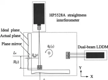
The flatness error of the plane mirror will also affect the positional reading in the direction normal to the mirror. This error should be calibrated in advance and stored for later compensation. The set-up for flatness calibration of X-plane mirror is illustrated in Fig. 5. During the stage motion in Y-axis, the L4positional reading may consist of (1) flatness
error of the plane mirror (␦mx(y)), (2) straightness error of
motion (␦x(y)), and (3) yaw error induced linear error
(S(y)z(y)). Therefore,␦mx(y) can be calculated as [Eq. (2)]:
␦mx(y)⫽ ⌬L4⫺␦x(y)⫹ S(y)z(y) (2)
where ⌬L4 and S(y) can be read by the LDS4 and LDS1
respectively, ␦x(y) can be measured by the HP straightness
interferometer,z(y) by the dual-beam LDDM (Laser Doppler
Displacement Meter, made by Optodyne Co.). The same ap-proach can be applied to the Y-plane mirror as well. By means of this method, the flatness errors of plane mirrors can be compensated to the accuracy of 0.1m in the later use.
3.5. Linear errors referred to a common point
A useful approximation is to treat the stage as a rigid body. In this case, all six motion errors are measured with respect to different points on the stage respectively. To
Fig. 4. Optical alignment of the optical reflection device.
Fig. 5. Flatness deviation calibration of reflectors.
convert all linear errors to a certain point P for a particular purpose, e.g., wafer lithography, a matrix transformation can be applied, that is [Eq. (3)]:
冋
⌬Xp ⌬Yp ⌬Zp册
⫽冋
⌬X⌬Y ⌬Z册
⫹冋
x y z册
⫻冋
XYpp⫺ X⫺ Y Zp⫺ Z册
(3)where x, z, yare the pitch, yaw and roll errors of the
stage, and ⌬X, ⌬Y, ⌬Z are the measured linear errors. x represents the vector cross product, and Xp⫺X, Yp⫺Y, Zp⫺Z are offsets from measured points to point P.
4. Principle of measurement
4.1. Measurements of displacement, pitch and yaw along the Y-axis
In the designed system, by taking three simultaneous linear distance measurements (L1, L2, and L3) parallel to the Y-axis
using LDS1, LDS2 and LDS3, one can obtain displacement, pitch and yaw errors along the Y-axis of the moving body at one measurement. In the system, the measured point is defined
as the center point P on the surface of the top plate and aligned in X-Y plane, so that the Abbe´ error introduced by the pitch and roll motions can be neglected. Moreover, assume that the coordinate system of the optical reflection device is aligned in line with the measurement axes and the surfaces of these mirrors are treated as ideal planes. When the center of the stage moves along the Y-direction, the actual displacement of point
P in the Y-axis can be obtained from the displacement of
LDS1, [Eq. (4)] i.e.
Y displacement共Ly兲 ⫽ L1 (4)
Similarly, when the center of the stage moves along the X-axis, the actual displacement of point P in the X-axis is [Eq. (5)]
X displacement共Lx兲 ⫽ L4 (5)
The yaw error of the stage can be computed by the differ-ence between the two laser displacements in the horizontal plane divided by the distance between these two beams (Dh). Yaw共z兲 ⫽ 共L3⫺ L2兲/Dhradian (6) where Dhis found to be 51.727 mm by experiment. This is done by rotating the plane mirror (PM1) a known angle (z),
and solving Dhwith Eq. (6).
Similarly, the pitch error in the Y-axis can be obtained from the difference between the two laser displacement readings (LDS1 and LDS2) in the vertical plane divided by the separation of these two beams (Dv). For small pitch, it is [Eq. (7)]
Pitch共x兲 ⫽ 共L1⫺ L2兲/Dvradian (7) where Dvis 51.308 mm by experiment.
Fig. 7. Relative dimensions among the laser beam, optical reflection de-vice, and top plate.
Fig. 8. Measuring principle of roll error. Fig. 9. Set-up for vertical straightness calibration.
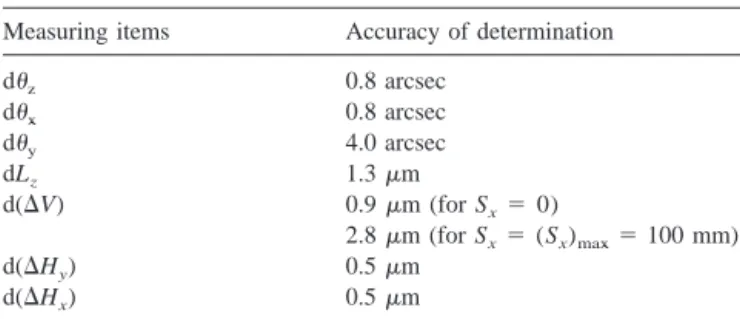
m (for Sx⫽ (Sxmax⫽ 100 mm)
d(⌬Hy) 0.5m
4.2. Measurement of straightness errors
The quadrant photo detector adopted in use is to sense the deviations of the beam [15]. Additionally, in order to eliminate the noise from foreign light sources, a band pass filter is placed in front of each photo detector. As shown in Fig. 6, when a stage is moved with a certain vertical dis-placement (␦), the laser beam reflected by the right-angle mirror will be shifted by a vertical distance of 2␦ which can be detected by the corresponding QD. Thus, the sensitivity of the vertical error measurement can be improved by a factor of 2. Since, in practice, this developed system can
only detect the vertical motion of the right-angle mirror, to realize the vertical motion of any particular point it is necessary to apply Eq. (3). In this system, the vertical straightness error of the right-angle mirror is detected by QD1, as seen in Fig. 1. It can also be seen from Fig. 7 that this measured error only refers to the point Q which is the incident point of beam LDS2 on the roof edge of the right-angle mirror. From Abbe´’s principle, the effective angular terms to compute the vertical straightness error at any other point on the top plate will be the pitch (x) and the
roll (y). Let the vertical straightness error measured at point
Q be v1/2 [Eq. (8)]. Then
Vertical error at point P:⌬V ⫽ v1/2⫹xSye⫺ySx (8) where Syedenotes the y displacement of point P relative to the roof edge, and Sxdenotes the x displacement of point P relative to the intersecting point O of LDS1 and LDS4 beams. In some applications, the objective of position con-trol is to concon-trol the vertical displacement at point O. The vertical error at this stationary point can be calculated from [Eq. (9)]:
Vertical error at point O: Lz⫽ v1/ 2⫹xSyo (9) where Syois the y displacement of point O relative to point
Q.
Based on rigid body kinematics, the horizontal straight-ness error of point P during Y-motion can be indirectly obtained from the lateral displacement of the plane mirror and the yaw rotation of the stage as [Eqs. (10) and (11)]:
Horizontal error along Y-axis:⌬Hy⫽ ⌬L4⫺zSy (10) Horizontal error along X-axis:⌬Hx⫽ ⌬L1⫹zSx (11)
Fig. 10. Vertical straightness calibration: (a) results; (b) residual errors.
Fig. 11. Residual errors of pitch calibration.
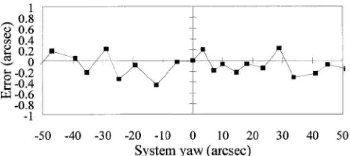
Fig. 12. Residual errors of yaw calibration.
where Sxand Sycan be obtained from the outputs of LDS4 and LDS1, respectively.
4.3. Measurement of roll error
As illustrated in Fig. 8, when the stage (or the reflection device) is moved with a rotation about the Y-axis, each reflected beam from the right-angle mirror will change its
Roll共y兲 ⫽ 共v1/ 2⫺ v2/ 2兲/Dhradian (12) where v1and v2are the vertical outputs of QD1 and QD2
respectively.
4.4. Estimation of system errors
In order to get an idea of the inaccuracy of the measure-ment system, every measuring term is estimated using par-tial differentiation. In comparison with an HP interferome-ter, the accuracy of the displacements (L1, L2, L3, L4) can be
measured by LDSs with the accuracy of⫾0.1m, and the deviations of beams (v1, v2) by QDs with the accuracy of
⫾1m. The measuring range of the displacement is limited
to 200 mm which simulates the travel of an 8-inch wafer stage. Assuming that the measuring range of the angular
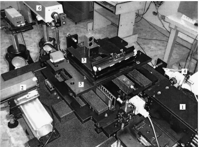
Fig. 14. Experimental set-up for testing the motion error of the stage.
Fig. 15. Photo of the experimental set-up (1: LDS head unit, 2: LDS4, 3: Optical reflection device, 4: Quadrant photo detector, 5: X-Y stage, 6: HP5528A interferometer).
errors is limited to⫾200 arcsec, then the differences among
L1, L2, and L3 are approximately⫾50 m. The distances
(Dh, Dv) and the positional parameters (Sx, Sy, Syo, Sye) can all be easily measured to the accuracy of⫾10 m.
Suppose that every measuring term Miis a function of a number of individual signals, sj, from the LDSs, detectors and positional parameters. The compound error of Mican be expressed as: [16]
dMi⫽ ⌺
冋
⭸Mi⭸sj
␦sj
册
(13)where dMi denotes the accuracy of determination of the measuring item Mi.
⭸Mi ⭸sj
is the differential coefficient of Mi with respect to a certain measuring parameter sj.According to Eq. (13), the accuracy of each measuring term can be derived from Eqs. (6 –12) and expressed as [Eqs. (4)–(20)]:
dz⫽ ⫾
冉
␦L3⫺␦L2 Dh ⫹共L2⫺ L3兲␦Dh Dh 2冊
radian (14) dx⫽ ⫾冉
␦L1⫺␦L2 Dv ⫹共L2⫺ L1兲␦Dv Dv2冊
radian (15) dy⫽ ⫾冉
␦v1⫺␦v2 2Dh ⫹v2⫺ v1 2Dh 2 ␦Dh冊
radian (16) dLz⫽ ⫾ 共␦v1/ 2⫹x␦Syo⫹ Syo␦x兲 (17) d(⌬V) ⫽ ⫾ 共␦v1/ 2⫹ Sye␦x⫹ Sx␦y⫹x␦Sye ⫹y␦Sx兲 (18) d(⌬Hy)⫽ ⫾ 共␦L4⫹ Sy␦z⫹z␦Sy兲 (19) d(⌬Hx)⫽ ⫾ 共␦L1⫹ Sx␦z⫹z␦Sx兲 (20) According to the above equations, we can find the esti-mated compound error for every measuring item as shown in Table 1.5. System calibration
The calibration tests for two positioning errors, a vertical straightness error, and three angular errors were carried out with an HP5528A interferometer measurement system. The resolution of the HP interferometer system is 0.01 m for displacement and straightness, and 0.1 arcsec for pitch and yaw. These two systems are set up on an optical table with vibration isolation and tested in a temperature and humidity controlled room (20⫾ 0.3°C, 40–60% humidity).
5.1. Calibration tests of linear errors
The accuracy calibration of X and Y positioning errors was made in direct comparison with the HP5528A readouts.
Fig. 16. Signal-processing diagram of the measurement system.
Fig. 17. Horizontal straightness error of the stage.
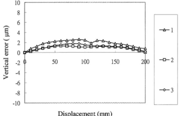
Fig. 18. Vertical straightness error of the stage.
Both errors are found to be better than⫾0.1m to the range of 200 mm. The vertical straightness error of the developed system was calibrated with reference to the HP straightness interferometer in a range of ⫾0.1 mm, with 10m incre-ment generated by a jack, as shown in Fig. 9. Fig. 10(a) shows the vertical characteristic curve. Fig. 10(b) indicates the calibrated errors of the system. The accuracy is found to be within⫾1.5 m for a measuring range of ⫾0.1 mm.
5.2. Calibration tests of angular errors
The tests of the roll and pitch error were carried out with two adjustable jacks. By adjusting the height of each jack, the roll and pitch motions could be generated. The calibra-tion of the yaw error was performed by rotating a rotary table at an increment of approximately 5 arcsec. Both the reflection device and the HP retroreflectors are mounted on this table for the calibration of the pitch, yaw and roll errors. Figs. 11, 12 and 13 show the calibrated results of the pitch, yaw and roll errors. Comparing the developed system with the HP system, the calibrated pitch and yaw errors are better than⫾1 arcsec and the roll error is –3 to 1 arcsec within the measuring range of⫾50 arcsec.
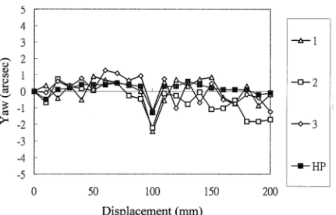
ence. Fig. 16 illustrates the signal-processing diagram of the measurement system. All the systems are set up in a tem-perature and humidity-controlled room. Using software compensation, the displacement measurements of LDSs are corrected for atmospheric effect. When the X-Y stage is moved point-by-point along the Y-axis, the system mea-sures and calculates the X- and Y-positions, horizontal and vertical straightness errors, and three rotational errors of the current position. The measured point is the center point P of the top plate. In this experiment, measurements were per-formed by moving the stage along the Y-axis for a distance of 200 mm, with an increment of 10 mm, for 3 runs. For comparison, the HP5528A interferometer was also used for the pitch and yaw measurements and a Wyler electronic level for the roll measurement, with the resolution of 0.2 arcsec. Figs. 17 to 21 show the individual motion errors of the stage. Experimental results show that the pitch and yaw measured by the system are consistent with those measured by the HP system and also the roll with respect to the electronic level.
7. Conclusions
This paper presents a newly developed system that is able to measure simultaneously the motion errors in 6-de-grees-of-freedom of the X-Y stage. The moving part is wire-less which eliminates any errors introduced by pushing and pulling the wires. The developed system is simple in prin-ciple and can be mounted on a precision stage to provide the real-time compensation signal of 6 degrees of freedom.
Acknowledgment
This report forms part of the project funded by the National Science Council of R.O.C. on the Development of High Precision Stages.
References
[1] Weck MM. Geometric and kinematic errors. Technology of Machine Tools, 1980, 5: 9 –12.
[2] Almanar IP. A study of pre-calibrated techniques for compensation of geometrical errors on large machine tools. Ph.D. thesis, UMIST, 1986.
[3] Fang CY, Fan KC. Development of multi-function error calibration system for NC machine tools. Proc. of the 3rd ROC-ROK Metrology Symposium, 1990, (Taipei, Taiwan): 163–71.
Fig. 20. Yaw error along Y-axis of the stage.
[4] Ni J, Huang PS, Wu SM. A multi-degree-of-freedom measuring system for CMM geometric errors. J Engng Ind, Trans ASME, 1992, 114: 362–9.
[5] Huang PS, Ni J. On-line error compensation of coordinate measuring machines. Int J Mach Tools Manufact, 1995, 35: 725–38.
[6] Chou C, Chou LY, Peng CK, Fan KC. CCD-based CMM geometrical error measurement using Fourier phase shift algorithm. Int J Mach Tools Manufact, 1997, 37: 579 –90.
[7] Tanimura Y. Reflection device of autocollimator for measuring the three components of angular alignment. Int J Japan Soc Prec Eng, 1994, 28: 275– 6.
[8] Shimizu S, Lee, HS, Imai N. Simultaneous measuring method of table motion errors in 6 degrees of freedom. Int J Japan Soc Prec Eng, 1994, 28: 273– 4.
[9] Fan KC, Chen MJ, Huang WM. A six-degree-of-freedom measure-ment system for the motion accuracy of linear stages. Int J Mach Tools Manufact, 1998, 38: 155– 64.
[10] Slocum AH. Precision Machine Design. Englewood Cliffs, N.J.: Prentice-Hall, 1992: 196.
[11] Sommargren GE. Linear/angular displacement interferometer for wa-fer stage metrology. Proc SPIE, 1989: 1088: 268 –72.
[12] Nakamura O, Goto M. Microscopic coordinate measurement by four-beam laser interferometry. J Japan Soc Prec Eng, 1993, 59: 155– 60.
[13] Tomita Y, Kodaira K, Satoh F, Itoh K, Koyanagawa Y. A 6-axes motion control method for parallel-linkage-type fine motion stage. J Japan Soc Prec Eng, 1992: 58: 684 –90.
[14] Bobroff N. Critical alignments in plane mirror interferometry. Prec Eng, 1993, 15: 33– 8.
[15] Madden RM. Silicon position sensing detectors for precision mea-surement and control. Advances in Optical Metrology, Proc SPIE, 1978, 153: 101–7.
[16] Galyer JFW, Shotbolt CR. Metrology for Engineers, 5th ed. London: Cassell, 1990: 6 –7.