Fast Vehicle and Pedestrian Detection Using 2D
Shapes and 3D Sizes
Yen-Liang Lin
∗, Ping-Han Lee
†, Yi-Ping Hung
† ∗Graduate Institute of Networking and MultimediaNational Taiwan University
†Department of Computer Science and Information Engineering
National Taiwan University
Abstract—Most existing pedestrian and vehicle detection algo-rithms use 2D features of objects, such as pixel values, color and texture, shape information or motion. The use of 3D features in object detection, on the other hand, are not well studied. In this paper, we propose a two-stage algorithm that uses both 2D and 3D features to detect pedestrian and vehicle in videos. The first stage compares the 2D contours between moving foreground and a set of object-specific shape kernels, to find the object candidates. A shape kernel is the contour of the object viewed from a certain panning and tilting angles, as well as a bounding cube that enclose this object. We have prepared 1584 and 1188 shape kernels for pedestrian and vehicle, respectively, and a speedup scheme is proposed to reduce the number of contour matching needed. The second stage further verifies the object candidates based on their 3D sizes, its width, height and length. Given shape kernels, the 3D sizes of the objects in a static scene monitored by a camera can be obtained using the intrinsic and extrinsic parameters of that camera. We employ a calibration-free method to estimate the camera parameters. The proposed algorithm can also handle partially occluded objects. Our experimental studies demonstrate that the proposed method can detect objects accurately and efficiently. It achieves a precision of 90%(90%) in detecting pedestrians(vehicles) at 15 frame-per-second.
Index Terms—vehicle detection, pedestrian detection I. INTRODUCTION
With the prevalence of the all kinds of cameras and advance-ment in computer hardwares, the computer aided surveillance systems have become realistic in recent years. The very basic issue in a computer aided surveillance systems is to detect the moving objects, or foregrounds in the scene. Intensive effort of researchers have been spent on this topic [1] [2] [3]. Typically the most interesting objects in a surveillance scene are moving pedestrians and vehicles. There are many works concerning pedestrian detection. An Adaboost algorithm based on both appearance and motion features was proposed to detect human in a single image [4]. Chen et al [5] proposed a new cascade structure, which consists standard Adaboost-stages [6] and meta-stages. Negative examples are further rejected in this structure, thus besides being accurate, their algorithm is also efficient at the same time. On elaborating feature extraction methods, Dalal et al [7] proposed the Histograms of Oriented Gradients (HOG) as a new feature extraction method, and demonstrated that HOG features are very effective in detecting human. To deal with the occlusion problems in crowded scene, Wu and Nevatia [8] decomposed the whole human bodies into
head-shoulder, torso and legs, and formulated the partially oc-cluded human detection problem as the maximum a posterior (MAP) estimation problem. More pedestrian detection works can be found in [9] [10].
There are also several works concerning vehicle detection problem. In the work proposed by Wang and Chen [11], the moving objects resulting from the spatial-temporal wavelet transform on difference of consecutive frames are regarded as vehicles in their work. Tan et al [12] proposed a two-stage vehicle detection algorithm. The first two-stage is a typical background learning procedure. The second stage classifies all the pixels in a frame into three categories, namely road surface, lane lines and others. The vehicle is defined as the moving objects in the road surface. Besides model-free algorithms [11] [12], there are some algorithms that model vehicles explicitly [13]. Song and Nevatia [13] used generic shape models of classes of vehicles. Under the Baysian framework, the hypotheses of vehicles are formed and upon which the posterior probabilities are calculated. Their algorithm was reported to have good performance when vehicles are occluded from each other. More vehicle detection works can be found in [14] [15] [16] [17].
Typically detecting objects in a single image requires sliding a detection window exhaustively on that image, probably with several different sizes. For each detection window, features of certain kinds (e.g. Harr-like feature) are extracted. Most of the existing pedestrian detection algorithms fall in this category [4] [5] [7] [8]. Basically the high computational complexity of such algorithms prohibits these algorithms from real-time applications. On the other hand, since usually we are more interested in moving objects than static objects, one can perform foreground detection first and detect objects of interest only in the foreground regions. In this way the computation is reduced significantly. Furthermore, potentially we can even eliminate some false alarm in the background regions. Some object detection algorithms of this kind are tailor-made for traffic monitoring system and these algorithms regard the moving objects as vehicles [11] [18].
The features for objects used in most existing object detec-tion algorithms include pixel values, Harr wavelet, color and texture, shape information and motion [19]. Basically these features are 2D features from 2D images. The use of 3D features in object detection, on the other hand, is not well
studied in the literature. The 3D features of objects in the scene can be derived using the parameters of the camera monitoring the scene. The camera parameters can be obtained through some camera calibration procedure, and this procedure can be made very simple. For example, the algorithm proposed by Chen et al [20] simply requires users to specify 6 points of a cuboid on a single frame captured by the camera. In this paper we propose a vehicle and pedestrian detection method that uses both 2D shapes and 3D sizes. We apply [20] to estimate the camera parameters in order to calculate the objects’ 3D sizes. Compared with the existing algorithms, the distinguishing features of the proposed algorithms are summarized as the following:
• It uses both 2D and 3D features, while most existing algorithms use only 2D features.
• It is a general object detection method and can be applied to detect pedestrian and vehicle, or other object classes, while most of algorithms deal with a single object class.
• With the introduction of the shape kernels, the proposed
method can also determine the poses and orientations of objects. By enforcing the consistency of objects’ poses and orientations across consecutive video frames, the proposed method can also be applied to perform object tracking. The aforementioned topic highlight our future research directions.
A. Related Work
Kanhere et al also used 3D information for vehicle detec-tion [18]. The calibradetec-tion process in [18] requires multiple consecutive frames with a vehicle moving precisely along the lane, and users are asked to specify 6 points or more in several designated frames. With the camera parameters, they found and tracked feature points in the scene and clustered these features based on their 3D features. All feature points belonging to the same cluster define an object, which are assumed to be a vehicle. Their work can handle some vehicle occlusion problems. However, their algorithm actually detects moving objects instead of a specific object class. Their work is not able to distinguish moving pedestrians and vehicles. Our work, on the other hand, models the two object classes explicitly and is able to distinguish them. Furthermore, their calibration procedure requires more user interactions than the cuboid algorithm we apply in this paper.
In our previous work, we proposed a pedestrian and vehicle detection algorithm using solely 3D features [21]. In video frames, our previous work extracts moving objects’ width and height, and uses these 3D features to verify whether or not a moving object is a pedestrian or a vehicle. Because of some simplifications made in our previous work, dubbed as the billboard model, it suffers in the following aspects:
• An object’s 3D size includes width, height and length.
Our previous work assumes that a moving object can be regarded as a billboard, and it neglects the object’s length. However, this assumption breaks when the objects are close to the camera.
• The extracted widths and heights are sensitive to the objects’ viewing angles, especially the tilting angles. A more robust 3D size extraction algorithm across tilting angles needs yet to be developed.
We propose the cube model that solves the aforementioned problems. The proposed algorithm extracts objects’ widths, heights and lengths robustly under different viewing angles and different objects’ distances to the camera. Furthermore, the proposed algorithm considers both object’s 2D shape and 3D sizes, and it achieves better results than our previous work. The rest of the paper is organized as the following. Section II gives an overview of the proposed algorithm. The proposed algorithm is introduced in Section III, which describes the cube model and the shape kernels (Section III-A), the 2D shape matching scheme (Section III-B) and the 3D size estimation method (Section III-C). The experimental results are included in section IV, followed by the conclusions and future works are given in section V.
II. OVERVIEW OF THEPROPOSEDSYSTEM
In this paper, we propose an algorithm that detects objects in videos based on their 2D and 3D features. Fig. 1 summarize the proposed algorithm. The objects’ 3D features can be derived if we have the intrinsic and extrinsic parameters of the camera monitoring the video scene. We apply the cuboid method [20] to estimate the camera parameters. This calibration process requires only one frame form the camera and needs users to specify only 6 points of a cuboid on a single frame captured by the camera.
Upon each frame we first detect the moving foreground using the codebook method [3] and remove shadow regions using the algorithm proposed by Zhou and Hoang [22]. The codebook algorithm adopts a quantization/clustering technique to construct a background model from a long video sequence. It captures the periodic motion and handle illumination varia-tions, an it is efficient in memory and speed. As for the shadow removal, generally speaking, we assume that the shadow regions are semi-transparent. An area cast into shadows often results in a significant change in intensity without much change in chromaticity. To utilize the color invariant feature of shadow, Zhou and Hoang [22] used the normalized color components in YUV color space to detect shadows, and we apply their algorithm in this paper.
Fig. 2 (a) illustrates a video frame, and Fig. 2 (b) shows the corresponding foregrounds with shadow removed. The resulting shadow-free foreground is further processed using morphological opening and closing to eliminate the noise. Then we find all the connected components in the processed foreground and draw a rectangle for each connected compo-nent, as shown in Fig. 2 (c). We define each resulting rectangle as a moving blob. A moving blob can be a pedestrian, a vehicle, or simply some foreground noise, and will be verified later.
To verify whether or not a moving blob is a pedestrian or a vehicle, we firstly find the edge map enclosed by this moving blob and compare it with a set of object-specific 2D shape
Fig. 1. The overview of the proposed system.
(a) an input frame (b) the foreground (c) a moving blob Fig. 2. Extraction of moving blobs in a video frame.
kernels. The shape kernels of an object class is a collection of the contours of that object observed from different viewing angles. We apply the chamfer distance when we calculate the distance between a moving blob and a shape kernel. This procedure can be seen as a template matching process, and a speedup scheme is also proposed. If a moving blob matches an object’s shape kernel, then we calculate the 3D sizes, the width, length and the height of the object in this moving blob. Two generative models are designed, one can determine whether a moving blob is a pedestrian or not, and the other can determine whether a moving blob is a vehicle or not. A moving blob is identified as a pedestrian or a vehicle if it matches both the 2D shape and the 3D size of that object class. Via using both 3D sizes and 2D shapes jointly, the proposed system achieves satisfying pedestrian and vehicle detection results.
III. OBJECTDETECTIONUSING2D SHAPES AND3D SIZES
A. The Cube Model and Shape Kernels
Given a moving blob resulting from the previous section, we assume there is only one object, or none, inside the associating rectangle. We will verify whether or not the content enclosed is a pedestrian or a vehicle in this Section. In the next Section we will not assume there is only one object in a moving blob anymore, and we propose a scheme that is able to find the occluded pedestrians and vehicles.
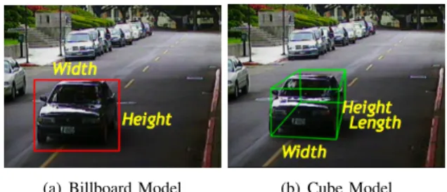
Assume we detect a moving blob shown as the red rectangle in Fig. 3 (a), the billboard model in [21] will give us the width and the height of this rectangle in the 3D space. As stated earlier, the extracted width and height are sensitive to the panning and tilting angles between the object and the camera, as well as the distance between them. To estimate the 3D size of an object inside a moving blob more precisely, we propose
(a) Billboard Model (b) Cube Model Fig. 3. Comparison of billboard model and cube model.
the cube model which calculates the width, height and length of that object in this paper. To do so, a bunch of object-specific shape kernelsare needed. A shape kernel is shown as the right most picture in Fig. 4. It is defined as the contour of the object extracted from a certain panning and tilting angles between the object and the camera, as well as the 3D cube that encloses this object. As shown in Fig. 4, the width, height and length, denoted as {W, H, L}, of the object can be calculated if we know the four vertices on the cube: W = P1P2, H = P1P4,
and L = P1P3.
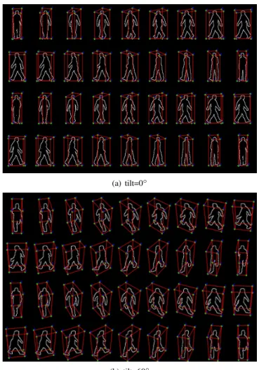
For each object class, the variation among all its possible contours, or shapes, is caused by (1) different viewing angles; (2) different appearance of the object. In order to efficiently encode the variance of the shape of each object, we choose a couple of the most representative types, and for each type we generate shape kernels viewed from hundreds of different camera angles. We choose four types for pedestrian: two are men and two are women, as shown in Fig. 5 (a), (b), (c), and (d). These pedestrian types are different in their body poses. We also choose three vehicle types, as shown in Fig. 5 (e), (f), and (g). For each object type, we prepare the corresponding 3D meshes and use the Autodesk Maya, a 3D computer graphics software, to render the contours of shape kernels and the cube enclosing the 3D meshes under a large number of different viewing angles of the virtual camera. These viewing angles are combinations of 36 panning angles ranging from 0◦ to 180◦ and 11 tilting angles ranging from 0◦ to 60◦, resulting in 396 shape kernels for an object type. Fig. 4 illustrates the process of generating the shape kernels. Table I shows the statistics of the shape kernels for pedestrian and vehicle. Fig. 6 and figure. 7 illustrates some examples of shape kernels for
pedestrian and vehicle, respectively.
Fig. 4. Generation of shape kernels.
(a) man1 (b) man2 (c) woman1 (d) woman2
(e) vehicle1 (f) vehicle2 (g) vehicle3 Fig. 5. Illustration of the object types used in this paper.
PEDESTRIAN VEHICLE #shape kernels 1584 1188 #types 4 3 #panning angles 36 36 #tilting angles 11 11 TABLE I
STATISTICS OF THE SHAPE KERNELS FOR PEDESTRIAN AND VEHICLE.
The object detection algorithm using the cube model is summarized as the following:
1) Find all the moving blob in the given video frame. 2) For each moving blob, calculate the edge map of the
enclosed image patch, and then obtain the distance-transformed(DT) image.
3) For each object-specific shape kernel, match its contour with the resulting DT image. We resize the shape kernel and make it to roughly have the same size with the moving blob.
4) If a shape kernel’s matching score exceeds a pre-defined threshold, we assume there is an object candidate inside this moving blob, and then the four vertices of this shape kernel are used to calculate the 3D size of this candidate. 5) The previous step may result in a candidate whose con-tour looks like an object, but its 3D size is inconsistent to the real object (e.g. a 10-meter-tall pedestrian or a vehicle of only 50 centimeter in length). We employ the object-specific classifier to exclude the candidates with wrong 3D sizes.
In the following, Section III-B will detail the matching between the contour of a shape kernel and the DT image patch
(a) tilt=0◦
(b) tilt=60◦
Fig. 6. Examples of shape kernels for pedestrian.
(a) tilt=30◦
Fig. 7. Examples of shape kernels for vehicle.
enclosed by the moving blob. Section III-C will derive the 3D width, height and length of an object enclosed by the moving blob using the shape kernel.
B. 2D Shape Matching
Given a video frame, for each moving blob detected we first inferwhether there exist object candidates inside this moving blob, and this inference are based on the 2D shapes. We apply well-know template matching method, chamfer matching, to find all matched shaped kernels.
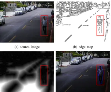
Chamfer matching was proposed by Barrow et al. [23] and later refined in [24]. Gavrila et al. [25] applied this technique to detect pedestrians in videos. Assume we find a moving blob,
(a) source image (b) edge map
(c) distance-transformed (DT) image (d) source image with a shape kernel superimposed
Fig. 8. A video frame and its edge map and the corresponding chamfer image. The image patch enclosed by the red rectangle in (c) is denoted as IDT.
shown as the red rectangle in Fig. 8 (a). The chamfer matching process is summarized as the following:
1) Calculate the edge map of the original frame. Fig. 8 (b) gives the edge map of Fig. 8 (a).
2) Based on the edge map, calculate the distance-transformed(DT) image, and it is shown as Fig. 8 (c). The DT image computes the distance of each pixel to the nearest edge pixels [23]. We denote the the image patch enclosed by the moving blob in the DT image as IDT.
3) Superimpose the shape kernel on the IDT. There may
be one, or multiple object candidates inside IDT, and
these candidates are possibly partially occluded by each other. To find all the candidates, we slide shape kernels of different sizes in IDT. The height of each shape kernel
ranges from 0.6 to 1.0 times of the height of IDT and
the ratio between width and height of the shape kernel is fixed when we resize the shape kernel. This step plays a cruical part in detecting occluded objects using the proposed method. Fig. 8 (d) illustrates a shape kernel superimposed on the DT image.
4) The distance between the contour of a shape kernel, denoted as Γ, and IDT can be written as
D(Γ, IDT) = 1 n X i IDT(Γi) (1)
where Γ = {Γ1, Γ2, ..., Γn} is the collection of pixel
locations on the contour of the shape kernel and n is the number of pixels on the contour.
If D(Γ, IDT) < θ, where θ is a pre-defined threshold, then
we infer there is an object candidate inside this moving blob.
The advantage of matching a shape kernel with the DT image rather than with the edge image is that the resulting similarity measure will be smoother as a function of the shape kernel transformation parameters.
For a moving blob, basically we will have to compare its DT image between all the shape kernels for a object class. In this paper, we have 1584 shape kernels and 1188 shape kernels for pedestrian and vehicle, respectively. To reduce the computation, a speedup scheme is proposed in the following section.
Speed Up Template Matching Scheme
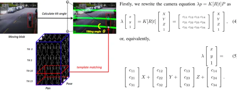
With knowing camera parameters, the lens center position, C, and its projection point, P , the middle point of the bottom of the moving blob can be obtained. Fig. 9 gives an illustration. The tilting angle, θ, of the moving blob can be derived:
θ = cos−1 −−→ GC ×−GP−→ −−→ GC −−→ GP
As the tilting angle of each shape kernel is known, we need
Fig. 9. Calculate the tilting angle of the moving blob.The green line denotes the tilting contour in the scene. C denotes the lens center, P denotes the project point of the lens center on the ground and G denotes the middle point of the bottom of the moving blob.
only to use the subset of shape kernels whose tilting angles equals to, or are close to θ when we perform the 2D shape matching, see Fig. 10.
There are two advantages of this speedup scheme:
• We use less shape kernels to execute the template match-ing process, which will speed up the matchmatch-ing process up to 11 times faster than using all shape kernels.
• Using only the shape kernels with correct θ can reduce a lot of false alarms caused by the matched shape kernel with incorrect θ.
C. 3D Size Estimation
In the previous section we have identified the object can-didates inside the moving blobs. Object candidates are those whose 2D shapes match the object’s contour, but we don’t know whether or not their 3D sizes match the certain object’s 3D size. In this section we will further verify the 3D sizes of object candidates. We will calculate the 3D sizes first, and
Fig. 10. Speedup template matching process.The red cube implies the subset of shape kernels, the tilting angles of which are closet to the tilting angle of the moving blob.For describing our method clearly, we only draw parts of our shape kernels.
based on which the object-specific classifier will perform the final object verification.
The object’s 3D size are its width, height and length, denoted as W , H and L respectively (see Fig. 11). Suppose a shape kernel matches a moving blob, and it is superimposed on the image, as illustrated in Fig. 11. In this case we know the four vertices on the image, p1, p2, p3 and p4,
where pi = {xi, yi}. In the following we will derive the
corresponding four vertices in the 3D space, P1, P2, P3 and
P4, where Pi = {Xi, Yi, Zi}. We will derive P1, P2 and P3
first, and based on P1, we can derive P4.
CalculatingP1,P2 and P3
Since typically the objects of interest are on the ground, we assume Z1 = Z2 = Z3= 0. Let’s focus on the point P1 for
the moment. With Z1= 0, we can rewrite the camera equation
λp = K[R3∗3| t3∗1]P, (2) as K[R(1)R(2)|t] X/λ Y /λ 1/λ = x y 1 , (3)
where R(i) is the i-th column in the rotation matrix R. The three unknown variables, X/λ, Y /λ and 1/λ, in equation (3) can be solved, and thus X and Y can be obtained via multiplying the first and the second variables by λ. Similarly, we can also solve P2= {X2, Y2, 0} and P3= {X2, Y2, 0}.
CalculatingP4
Once the we solve P1 = {X1, Y1, 0}, we can also solve
P4 = {X4, Y4, Z4} with the assumption X1 = X4, Y1 = Y4.
Firstly, we rewrite the camera equation λp = K[R|t]P as
λ " x y 1 # = K[R|t] X Y Z 1 = " c 11c12c13c14 c21c22c23c24 c31c32c33c34 # X Y Z 1 , (4) or, equivalently, λ x y 1 = (5) c11 c21 c31 X + c12 c22 c32 Y + c13 c23 c33 Z + c14 c24 c34 .
Using the fact that λ = c31X + c32Y + c33Z + 1 and simplify
equation 6, we have c13− c33x c23− c33y 0 Z = (6) (c31x − c11)X + (c32x − c12)Y + (c34x − c14) (c31y − c21)X + (c32y − c22)Y + (c34y − c24) 0 .
Note that the third equation can be eliminated and now we have 2 equations with 1 unknown variable Z. The Z can be estimated using the least-mean-square method. The authors in [18] had also derived how to solve X3, Y3 and Z1 between a
pair {P1, P3} in a similar scenario, and basically our derivation
yields the same result with theirs. With P1, P2, P3 and P4
solved, we associate the cube in 2D image with a cube in 3D space, the 3D features of which are W = dist(P1, P3),
H = dist(P1, P3) and L = dist(P1, P2). dist(Pi, Pj) is the
distance between Piand Pj in 3D space. Note that the W , H
and L of a real pedestrian, or vehicle, should be in consistent in different scenes or different locations with different viewing angles in the same scene.
Object Verification Based on 3D size
The resulting 3D size Ωx = {Wx, Hx, Lx} of the object
candidate is verified using the object-specific classifier. There are two main sources of error which make Ωxs
noisy. One is the object localization error in ’noisy’ contour image using shape kernels, the other is the error in coordinate transformation from 2D image plane to 3D space using the cuboid method. These error are assumed to be Gaussian, and we construct a generative model for each object class. For each of the two object classes, its training samples are re-sulted from the above 3D size estimation process of manually specified 500 pedestrian locations and 300 vehicle locations. These samples are collected from several other videos with different camera viewing angles. More precisely, for each object class, we fit all the pedestrian training data into a normal distribution to obtain the N (µp, Σp), and likewise we
obtain N (µv, Σv). Using the generative model achieves good
detection rate in our experimental study, more importantly, its low computational complexity makes it excellent choice for the real-time application. When detecting an object class in video, take the pedestrian for example, we say that a pedestrian is detected, if the Mahalanobis distance between its associated generative is below a pre-defined threshold. The Mahalanobis distance between a new observation Ωx and N (µp, Σp) is
q
(Ωx− µp)TΣ−1p (Ωx− µp).
IV. EXPERIMENTALRESULTS
We evaluate the proposed algorithm on outdoor video sequences with the resolution of 320*240. These video se-quences are different from the sese-quences used for training our object models and contains both pedestrians and vehicles. We manually annotate all pedestrians and vehicles with both width and height greater than 20 pixels (i.e. we specify the corresponding rectangles and the object class labels.). To calculate the accuracy, we define a successful detection being the detected rectangle occupies at least 50% of a ground truth rectangle and its size is no greater than 200%1of that ground
truth rectangle.
We have compared our algorithm with a pedestrian detection algorithm [5], a simple 2D Ratio Model, and our previous work [21], denoted as the Billboard Model. The 2D Ratio Model simply uses the ratio between the height and width of the moving blob as the features to detect vehicle and pedestrian. Table II includes pedestrian and vehicle detection results. We can see in this table that the proposed method has comparable performance to [5]. However, the proposed algorithm, is 7 times faster than [5]. It achieves 15 fps while [5] is only 2 fps, on a laptop with 1.66 GHz Intel core2 CPU. Furthermore, [5] can only detect pedestrian, while the proposed algorithm can detect both pedestrians and vehicles. In additional, among
1The accuracy of the algorithm in comparison [5] is affected by the size
of detecting rectangles. We found that the accuracy drop significantly when this value being smaller than 300%, under which precision and recall are 87.0% and 80.0%. The proposed algorithm, on the other hand, has the same performance when this values equals to 120% and 300%. The proposed algorithm has much more compact detection results compared with [5].
Pedestrian(#1524) Vehicle(#895) Precision Recall Precision Recall
[5] 53% 50% n\a n\a
2D Ratio Model 92% 73% 83% 62%
Billboard Model [21] 96% 71% 96% 48%
The proposed 90% 86% 90% 91%
TABLE II
PEDESTRIAN AND VEHICLE DETECTION RESULTS.
(a) (b)
(c) (d)
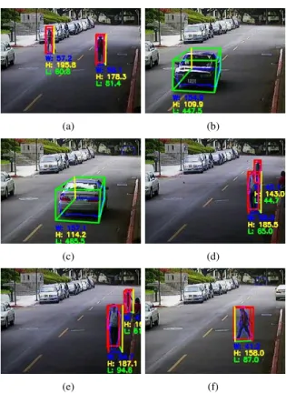
(e) (f)
Fig. 12. Some results of vehicle and pedestrian detection. Where the blue contour within the cube denotes the best matched shape kernels, the red and green cube denotes detecting pedestrian and vehicle respectively.The W(width), H(height), L(length) of a object in the 3D space are shown on the bottom of the 3D bounding box
all 1524(895) of pedestrians(vehicles), only 18(6) are wrongly detected as vehicles(pedestrians). Only 24 pedestrians and vehicles out of 2419 ones (0.9%) are wrongly detected as the other. This result shows that the generative models for the two object classes are well separated from each other, making the proposed algorithm very effective in discriminating the two classes.
V. CONCLUSIONS ANDFUTUREWORKS
In this paper we proposed a two-stage object detection system using both 2D shapes and 3D sizes, which are width, height and length of objects. We created 1584 shape kernels for pedestrian and 1188 shape kernels for vehicle. These shape kernels are taken under many combinations of panning and tilting angles, and they are effective in matching objects’ 2D contours and 3D sizes. To handle the partially occlusion of objects, a scheme that slides shape kernels in the occluded
foreground regions is also proposed. The proposed algorithm is able to detect pedestrians and vehicles with precision of 90% and 90% at 15 frame per second. We also find that the proposed algorithm is able to effectively discriminate pedestrians and vehicles. This may primarily due to the width, height and length of pedestrians and vehicles are very different from each other. The proposed algorithm performs reasonably well when the occlusion between objects are not significant.
The introduction of the shape kernels not only allow us to detectobjects based on their 2D and 3D information, but it also enable a new way to track objects. Since each shape kernel has its own attributes, the panning and tilting angles, and the type, we can assume that the same object in the consecutive frames should have similar panning and tilting angles, and their type should be the same. Our future work will model this relationship using the Hidden-Markov Model, and apply it to the object tracking problem.
VI. ACKNOWLEDGEMENTS
This paper is mainly supported by Construction of Vision-Based Intelligent Environment, National Chiao Tung Univer-sity of Taiwan under grant NO. 97-EC-17-A-02-S1-032.
REFERENCES
[1] C. Stauffer and W. Grimson, “Adaptive background mixture models for real-time tracking,” Computer Vision and Pattern Recognition, vol. 2, no. -252, 1999.
[2] W. L.Li, I. Y.-H. Gu, and Q. Tian, “Statistical modeling of complex backgrounds for foreground object detection,” IEEE Transactions on Image Processing, vol. 13, pp. 1459–1472, 2004.
[3] T. H. C. Kyungnam Kim, “Real-time foreground-background using codebook model,” Real-Time Imageing, vol. 11, pp. 172–185, 2005. [4] P. Viola, M. Jones, and D. Snow, “Detecting pedestrians using patterns
of motion and appearance,” ICCV, vol. 2, pp. 734– 741, 2003. [5] Y.-T. Chen and C.-S. Chen, “A cascade of feed-forward classifiers for
fast pedestrian detection,” ACCV, pp. 905– 914, 2007.
[6] P. Viola and M. Jones, “Rapid object detection using a boosted cascade of simple features,” CVPR, pp. 511–518, 2001.
[7] N. Dalai and B. Triggs, “Histograms of oriented gradients for human detection,” CVPR, vol. 1, pp. 886–893, 2005.
[8] B. Wu and R. Nevatia, “Detection of multiple, partially occluded humans in a single image by bayesian combination of edgelet part detectors,” ICCV, vol. 1, pp. 90–97, 2005.
[9] Q. Zhu, M.-C. Yeh, and K.-T. Chen, “Fast human detection using a cascade of histograms of oriented gradients,” CVPR, vol. 2, pp. 1491– 1498, 2006.
[10] B. Wu and R. Nevatia, “Cluster boosted classifier for view, multi-pose object detection,” International Conference on Computer Vision, vol. 2, pp. 1491–1498, 2007.
[11] Y.-K. Wang and S.-H. Chen, “A robust vehicle detection approach,” IEEE Conference on Advanced Video and Signal Based Surveillance, pp. 117– 122, 2005.
[12] X. Tan, J. Li, and C. Liu, “A video-based real-time vehicle detection method by classified background learning,” World Transactions on Engineering and Technology Education, vol. 6, pp. 189–192, 2007. [13] X. Song and R. Nevatia, “A model-based vehicle segmentation method
for tracking,” ICCV, vol. 2, pp. 1124–1131, 2005.
[14] R. Taktak, M. Dufaut, and R. Husson, “Road modelling and vehicle detection by using image processing,” IEEE International Conference on Systems, Man, and Cybernetics, Humans, Information and Technology, vol. 3, pp. 2153–2158, 1994.
[15] G. B. Z. Sun and R. Miller, “On-road vehicle detection using gabor filters and support vector machines,” International Conference on Digital Signal Processing, 2002.
[16] Z. Sun, G. Bebis, and R. Miller, “Improving the performance of on-road vehicle detection by combining gabor and wavelet features,” The IEEE 5th International Conference on Intelligent Transportation Systems, pp. 130–135, 2002.
[17] N. Chumerin and M. V. Hulle, “An approach to on-road vehicle detec-tion, description and tracking,” IEEE Workshop on Machine Learning for Signal Processing, no. 265-269, 2007.
[18] N. K. Kanhere, S. T. Birchfield, and W. A. Sarasua, “Vehicle segmenta-tion and tracking in the presence of occlusions,” Intelligent Transporta-tion Systems and Vehicle-Highway AutomaTransporta-tion, pp. 89– 97, 2006. [19] L. M. Brown, “View independent vehicle/person classification,” in
Pro-ceedings of the ACM 2nd international workshop on Video surveillance and sensor networks, 2004, pp. 114–123.
[20] C. S. Chen, C. K. Yu, and Y. P. Hung, “New calibration-free approach for augmented reality based on parameterized cuboid structure,” ICCV, vol. 1, pp. 30–37, 1999.
[21] P.-H. Lee, Y.-L. Lin, T.-H. Chiu, and Y.-P. Hung, “Real-time pedestrian and vehicle detection in video using 3d cues,” ICME, 2009.
[22] J. P. Zhou and J. Hoang, “Real-time robust human detection and tracking system,” CVPR Workshops, pp. 149–149, 2005.
[23] H. Barrow, R. B. J.M. Tenenbaum, and H. Wolf, “Parametric correspon-dence and chamfer matching: Two new techniques for image matching,” IJCAI, 1977.
[24] G. Borgefors, “Hierarchical chamfer matching: A parametric edge matching algorithms,” PAMI, 1988.