Guiding Acoustic Wave Characteristic Analysis with 2D Phononic Crystal
Jia-Yi Yeh
Department of Information Management, Chung Hwa University of Medical Technology.
E-mail : yeh@mail.hwai.edu.tw
Abstract
The wave propagation characteristics of the selective phononic crystals with defect will be studied in the study. It is used to design a new type of devices according to the characteristics of the band gaps of the phononic crystals (PCs). Additionally, the selective materials are combined and used to be as different types of defects in the system and the characteristics of the wave propagations of the system are investigated. The band structures and transmission characteristics of the perfect and defect modes of the phononic crystal are obtained by The plane wave expansion method and supercell calculation.
Keywords: phononic crystal, defect, waveguide, supercell.
1. Introduction
Within the last two decades, there has been a great deal of interest in photonic crystals (PCs). The PCs named acoustic/sonic band gap media are the elastic analogues of photonic crystals and have also received renewed attention recently [1,2]. A phononic crystal means a number of identical structural components which are composed together to form the structure. The PCs exhibit unique dynamic characteristics that make them act as elastic or acoustic filters for wave propagation and have unique characteristics called “phononic band gaps” (PBGs) within which sound and vibrations are forbidden.
James et al. [3] presented the propagation of an acoustic wave through one-dimensional PCs and calculated the transmission coefficients of various finite structures. Then, for two-dimensional PCs, extensive work has been done on analyzing the propagation of the elastic wave. As to the composite systems constituted by periodic inclusions of a given material in a host matrix, the PBGs were investigated and calculated theoretically and experimentally by Kushwaha et al. [4] and Montero et al. [5]. Straight or bent line defects introduced in a PC had been shown to be able to act as acoustic waveguides in many studies. The transmittivity through straight and stublike waveguides in a two-dimensional phononic crystal were investigated by Khelif et al. [6]. Then, Li and Liu [7] obtained the Bending and branching of acoustic waves in two-dimensional phononic crystals with linear defects in their studies. Lanzillotti-Kimura et al. [8] studied the Phonon engineering with acoustic nanocavities of theoretical considerations on phonon molecules, band structures, and acoustic Bloch oscillations.
Several theoretical methods have been used to study the dynamics for wave propagation in PCs, such as, the plane-wave expansion (PWE) method, the finite difference time domain (FDTD) method and the multiple-scattering theory (MST). Among these methods, the PWE method is most extensively used to calculate band structure because of its convenience. The PWE method was adopted to investigate the characteristics of the periodic system by Kushwaha et al. [9]. Tanaka, Tamura [10] and Garcia-Pablo [11] adopted the finite difference time domain method to study the wave propagation problems of the PCs. Additionally, Kafesaki, Economou [12] ©2007 National Kaohsiung University of Applied Sciences, ISSN 1813-3851
and Lai [13] studied the wave propagation problems by multiple scattering theory.
The Guiding acoustic wave characteristic of the PCs are studied and the defect bands, band structures are also determined in this study. The calculation is based on the plane wave expansion method and the defect mode is obtained by supercell calculation. This work investigates the acoustic wave in linear defects of 2D PCs which are composed of steel cylinders with square arrays embedded in air background. In addition, the propagation characteristics in the PCs was calculated in this study by using commercial software, COMSOL Multiphysics [14].
2. Analytical Model and Calculation Method
In this paper, the band structure of the two-dimensional periodic PCs with point defect is studied. The justification is that this seems to be the only case in which the wave equation for inhomogeneous solids greatly simplifies. The wave equation of the PCs is known to be:
) ( ) ( 2 1 2 1 11 P P ∇ ⋅ ∇ = ∂ ∂ − − ρ t C , (1)
where ρ is the mass density, is the longitudinal elastic constant, is the longitudinal speed of acoustic wave, is the pressure, and is the two-dimensional nabla. Making use of the periodicity of the PCs system, the quantities and can be expanded in the two-dimensional Fourier series as the following equations: 2 11 cl C =ρ
c
l P ∇ ) ( 1 r − ρ C11−1(r)∑
⋅ − = G r iG e r) ( ) ( 1 ρ G ρ , − =∑
⋅ , (2a,b) G r iG e r C111( ) τ(G)where G is the two-dimensional reciprocal-lattice vector.
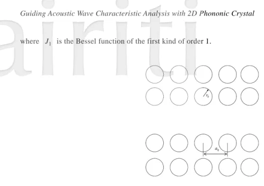
As shown in Fig. 1, the supercell with 5x5 circular cylinders (material A, steel) embedded in a background medium (material B, air), and introduces a defect by removing a central cylinder, to form two dimensional lattices with lattice spacing
a
0. The corresponding densities of the system are ρ and A ρ , respectively. Then, the B Fourier coefficient can be written as follows:⎪⎩ ⎪ ⎨ ⎧ ≠ Δ ≡ ⎭⎬ ⎫ ⎩⎨ ⎧ − × − = ≡ − − + − = − − = ⋅ − − = × ⋅ − − − − − −
∑
∑
) ( ) ( ), for 0 ( ) ( ) ( 0 for , ] ) 1 ( 1 [ ) 1 ( ) ( 1 1 [( , ) ] (0,0) 1 1 1 2 1 2 1 2 2 1 G G G G G G G F e e F f N f N N N m i N N m a m m i B A B A ρ ρ ρ ρ ρ ρ ρ (3) in which, 2 0 2 2 0 a N rf =π is the filling fraction of one cylinder in the supercell and F(G) is the structure factor. An equation analogous to Eq.(3) can be written for τ(G) in terms of . For the cylinder with radius in present system, the structure factor F(G) can be written as follows:
1 11− C
r
0 0 0 1( ) 2 ) ( r r J f F G G G = , (4)where J1 is the Bessel function of the first kind of order 1.
Fig.1. The 5x5 supercell with a linear defect.
Then, the eigenvalue equation can be obtained as the following form by applying the Bloch theorem:
∑
≠ ′ − − − − + − ′ + Δ + ⋅ + ′ −Δ − ′ ′ = G G k k G k G k G G G G G k ( ) ]P ( ) [ ( ) ( ) ( ) ] ( )P ( ) 0. [ρ 1 2 C111 ω2 ρ 1 C111ω2 F (5)This is a set of linear, homogeneous equations for the eigenvectors Pk(G) and eigenfrequencies ω(k) if G is permitted to take all the possible values. The Band structures of the PCs can be obtained by letting k scan the area of the irreducible region of the Brillouin zone as shown in Fig. 2.
Fig. 2. The first Brillouin zone of a square lattice crystal
Additionally, the COMSOL Multiphysics 3.4 software is used to simulate the acoustic wave propagation in the PCs with a point defect and the equation utilized to analyze present problem and pressure fields in the cavity of the PCs is the following equation:
P P 2 2 l c ρ ω ρ = ∇ ⋅ ∇ − . (6)
3. Results and Discussions
In this study, the guiding acoustic wave characteristics of the PCs system with linear defect consisting of steel cylinders in air background are presented. The materials properties and relative parameters are
, , , and 3 / 7800kg m A = ρ 3 / 2 . 1 kg m B =
ρ cA=6100m/s cB =343m/s. Besides, the filling fractions of the cylinder in the unit cell, 02
2 0 a
r
f′=π , investigated and discussed in this paper are 0.4 (r0 a0 =0.3568) and 0.5 (r0 a0 =0.4).
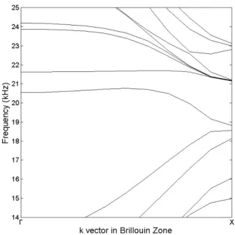
Fig. 3 show the waveguide band structures with filling fraction f′=0.4 for the PCs with linear defect. The linear defect is created by removing a single cylinder from the middle of the perfect PCs. According to the plane wave expansion method and supercell calculation, the band structure of the PCs with linear defect can be calculated. The defect band of the PCs can be observed in the band gaps of the perfect PCs. The defect band can act as the pass band and the acoustic wave can pass through the PCs with linear defect at the frequency of the defect band. Besides, the frequency of the defect band is called the resonant frequency of the defect and the acoustic will be localized in the linear defect.
Fig. 3. waveguide band structure for the PCs with filling fraction f =0.4.
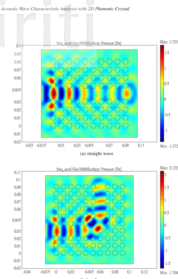
Fig. 4 shows the simulated results of the pressure fields of the PCs with linear defect with the filling fractions 0.4. Fig. 4(a) and (b) present propagation characteristics for the straight and bending acoustic wave, respectively. It can be observed that the acoustics wave can be restricted in the waveguide within specific frequency. Additionally, the acoustic wave also can be propagated in the designed waveguide as the results in Fig. 4(b). According to the numerical results, it can be utilized to design some acoustic waveguide of the PCs and used to design the novel acoustic devices in the mechanical applications.
= f
(a) straight wave
(b) bending wave
Fig. 4. Pressure field simulation of the PCs with linear defect
The waveguide band structures with filling fraction f′=0.5 for the PCs with linear defect are presented in Fig.5. It can be seen that the characteristics of the PCs with different filling fraction can change the restricted frequency. Additionally, the wave propagation characteristics of the PCs can be used to design controllable acoustic device according to the results.
Fig. 5. waveguide band structure for the PCs with filling fraction f =0.5.
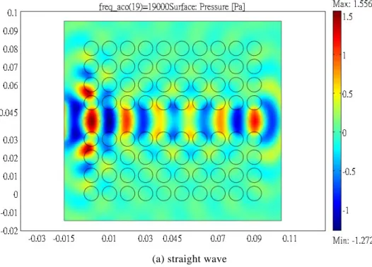
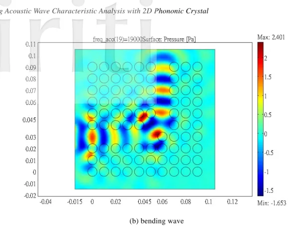
Fig. 6 shows the simulated results of the pressure fields the PCs with linear defect with the filling fractions 0.5. Fig. 6(a) and (b) present propagation characteristics for the straight and bending acoustic wave, respectively. The acoustics wave can be restricted in the waveguide within different frequency from the simulated results. On the other hand, the acoustic wave propagation in the designed waveguide also can be obtained as shown in Fig. 6(b).
= f
(b) bending wave
Fig. 6. Pressure field simulation of the PCs with linear defect
4. Conclusions
In this paper, the guiding acoustic wave characteristics of the PCs with linear defect are presented and the defect bands, band structures are also determined. The calculation is based on the plane wave expansion method and the defect mode is obtained by supercell calculation. The following conclusions can be drawn according to the numerical and simulated results. The incident acoustic wave of the resonant frequency will propagate along the designed waveguide (linear defect) of the PCs according to the numerical and simulated results. And, the band gaps of the PCs can be controlled with different filling fraction and also can be used to design some acoustic devices. Finally, , the propagation characteristics of the PCs with various linear defect can be utilized to design some novel acoustic devices. In this study, those analytical results can be used in the development of the novel acoustic applications for the PCs with defects.
Acknowledgements
This research was partially supported by the National Science Council in Taiwan through Grant NSC 99-2221-E-273-001-.
Reference
[1] Vasseur J.O., Djafari-Rouhani B., Dobrzynski L., Kushwaha M.S. and Halevi P., “Complete acoustic band gaps in periodic fibre reinforced composite materials: the carbon/epoxy composite and some metallic systems,“ Journal of Physics: Condensed Matter, Vol.6, pp. 8759,1994.
[2] Goffaux C. and Vigneron J.P.,” Theoretical study of a tunable phononic band gap system,” Physical Review B, Vol. 64, pp. 075118, 2001.
[3] James R., Woodley S.M., Dyer C.M. and Humphrey V.F., “Sonic bands, bandgaps, and defect states in layered structure-Theory nad experiment,” Journal of the Acoustical Society of America, Vol. 97, pp. 2041, 1995.
[4] Kushwaha M.S., Halevi P., Dobrzynski L. and Djafari-Rouhani B., “Acoustic band structure of periodic elastic composites,” Physical Review Letters, Vol. 71, pp. 2022, 1993.
[5] Montero de Espinoza F.R., Jimenez E., and Torres M., “Ultrasonic Band Gap in a Periodic Two-Dimensional Composite,” Physical Review Letters, Vol. 80, pp. 1208, 1998
[6] Khelif A., Djafari-Rouhani B., Vasseur J.O., Deymier P.A., Lambin Ph. and Dobrzynski L., “Transmittivity through straight and stublike waveguides in a two-dimensional phononic crystal,“ Physical Review B, Vol. 65, pp. 174308, 2002. [7] Li X.C. and Liu Z.Y., “Bending and branching of acoustic waves in two-dimensional phononic crystals with linear
defects,“ Physics Letter A, Vol. 338, pp. 413, 2005.
[8] Lanzillotti-Kimura N.D., Fainstein A., Balseiro C.A. and Jusserand B., “Phonon engineering with acoustic nanocavities: Theoretical considerations on phonon molecules, band structures, and acoustic Bloch oscillations,”Physical Review B, Vol. 75, pp. 024301, 2007.
[9] Kushwaha M. S. and Halevi P., “Giant acoustic stop bands in two-dimensional periodic arrays of liquid cylinders,” Applied Physics Letters, Vol. 69(1), pp. 31, 1996.
[10] Tanaka Y. and Tamura S.I., “Two-dimensional phononic crystals: surface acoustic waves,” Physica B, Vol. 263, pp. 77, 1999.
[11] Garcia-Pablo D., “Theory and Experiments on Elastic Band Gaps,” Physical Review Letters, Vol.84, pp. 4349, 2000. [12] Kafesaki M. and Economou E.N., “Multiple-scattering theory for three-dimensional periodic acoustic composites,”
Physical Review B, Vol.60, pp. 11993, 1999.
[13] Lai Y., Zhang X. and Zhang Z.Q., “Engineering acoustic band gaps,” Applied Physics Letters, Vol. 79, pp. 3224, 2001. COMSOL 3.4a, The COMSOL Group, Stockholm, Sweden.