A
N E W DESIGN AND IMPLEMENTATION
O F
8 x 8
2-D D C T / I D C T
Yung-Pin Lee Liang-Gee Chen Mei-Juan Chen
Chung-Wei K u
DSP/IC Design Lab, Dept. of' Electrical Engineering National Taiwan University
Taipei, Taiwan, R.O.C.
A b s t r a c t - We describe a novel 8 x 8 2-D DCT/IDCT a r c h i t e c t u r e based on t h e direct 2-D approach a n d t h e r o t a t i o n technique. The com- p u t a t i o n a l complexity is reduced by taking advantage o f ' t h e special at- t r i b u t e of c o m p l e x n u m b e r . Unlike other direct approach, t h e proposed a r c h i t e c t u r e is regular, hence, i t is suitable for VLSI implementation.
I N T R . 0
D
U C
T I 0 N
Among various transform techniques for image compression, the discrete cosine transform ( D C T ) is the most popular and effective one in practical applications because it gives a n almost optimal performance and can be im- plemented at a n acceptable cost. There are three methods t o realize N x N 2-D D C T : (1) indirect method by the row-column decomposition[1],[2]; (2) direct method [3],[4], such as using polynomial transform [ 3 ] ; (3) using other transforms, such as D F T and DHT. T h e indirect method has the advantage of regularity for VLSI implementation. Therefore, most chips for 2-D D C T had been implemented by indirect method[l],[2]. However, the computation amount of the indirect method is more tha.n t h a t of the direct method. T h e direct method requires less computations, but it incurs the irregularity. T h u s , the direct method is not suitable for chip implementation. Nevertheless, t h e feature of low computation complexity is still a,ttractive. T h e fact motivates t h a t a low-computation and regular 2-D D C T structure is researched recently.
In this paper, we propose a cost-effective architecture for 8 x 8 2-D DC- T architecture which bears both the advantages of high regularity a,nd less computation amount. A t first, the real number .input is mapped into corn- plex number in the N x N 2-D DCT[3]. Then the computation complexity can be reduced 6 y the rotation techniques in the complex number system. For 8 x 8 2-D D C T / I D C T , further modification is required t o make the ar- chitecture more regular and this results in the fact tha,t the architecture can be folded t o a n economically-allowable size for VLSI implementation. T h e fi- nite wordlength analysis demonstrates tha,t the proposed architecture requires less internal bits t h a n other methods. In the following section, we illustrate
CT/IDCTs and some additional summations. Wit,h some rnodificdtions, wc can obtain a more regular architecture for 8 x 8
2-D
DCT/IDCTs. Finally, we analyze the internal wordleiigth problem.METHODOLOGY
The Mapping of Input Data
T h e 2-D D C T of a n N x N real signal zn1,,, is defined as
c(0) =
.i
and c ( n ) = 1 for n#
0 ,A’
For convenience, we introduce
c ( n , ) / N so t h a t
a n d
x k I k a
Ykl,k2
by neglecting the kernal factor 2 c ( n l ) .In the following, we will assume N t o be a power of 2 . IJsing t h e permiita- tion[3], signal z,,,,, can be permuted as:
Z 2 n 1 , 2 n 2 X Z N - - Z n l - l , Z n 2 X 2 n 1 , 2 N - 2 n z - 1 2 2 ~ - 2 ~ ~ - - 1 , 2 ~ - 2 ~ ~ - - 1 n1 = 0, ’ . . , N / 2 - 1 , n 1 = N / 2 , . . . ,
N
- 1, n1 = 0, . . . , N / 2 - 1 , .n1 = N / 2 , . . . ~ N - 1, ‘n2 z 0, - . - , N I 2 - 1 n 2 = 0 , - - . , N / 2 - 1 n2 = N / 2 , . . . , N - 1 n2 = N / 2 , . . . ,N
- 1. - Y n l , n z - - - __ __ - -(2a) can be rewritten as:
( 3 )
1
N - 1 N - 1
Y k 1 , k z Y n l ; n 2 C O S
[
2n(4n;; 1 ) h nl=ll n2=11Now consider the following expression:
n l = l l n2=11
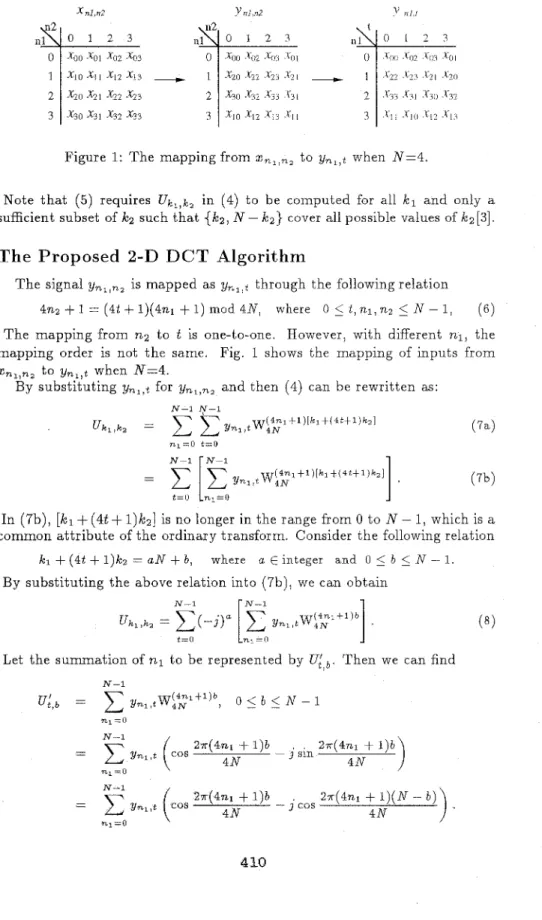
Figure 1: T h e mapping from x,,,,, to ynl,t when N=4
Note t h a t (5) requires U k l , k z in (4) t o be computed for all k l a n d only a
sufficient subset of IC2 such t h a t {ICs, N - ka} cover all possible values of Ic2[3].
T h e Proposed
2-D
D C T Algorithm
T h e signal y n l , n 2 is mapped as ynl)t through the following relation
0
5
t , n l , n z5
N - 1 ,4nz
+
1 = (4t+
1)(4nl+
1) mod 4 N , where (6)The mapping from n2 to
t
is one-to-one. However, with different n1, themapping order is not t h e same. Fig. 1 shows the mapping of inputs from
xn1,,, t o y n l , t when N=4.
By substituting ynl,t for ynl,n2 a n d then (4) can be rewritten as:
N-1 N-I n l = 0 t=O N-1 N-1 (7b) - ( 4 % t l ) [ k l S ( 4 t t l ) k ~ 1 -
5
[Z"yn1.-.4NIn (7b), [IC1
+
(4t+
l)lc~] is no longer in the range from 0 to N - 1, which is acommon attribute of the ordinary transform. Consider t h e following relation
IC1
+
(4t+
1)kz = U N+
b , where a E integer and 0 5 b 5N
- 1 By substituting the above relation into (7b), we can obtainIt is clear that is a complex number. However, its real part is indeed an N-point 1-D DCT, and its imaginary part is relative t o the real part by the relation:
I":,b> = 0
Im{Ui,b} = - R e { U & - t , b } , 1 5 t , b
5 N
- 1This reveals that U& can be achieved by calculating N-point 1-D DCT. Since the term belongs sign operation, only additions and subtractions are needed. Therefore, a n
k'
x N 2-D DCT can be realized by N N-point1-D DCT's with some additions. Nevertheless, the row-column method nerds 2 N N-point 1-D DCT's. Similar result has been deduced in [4] with different approach, but its structure is not regular, and so is unsuitable for VLSI implementation. To overcome this problem, the proposed algorithm develops
a regular architecture as illustrated in the following section.
ARCHITECTURE O F A N
8 x 8
2-D
DCT/IDCT
To realize the 2-D DCT, the additions are always irregular, ?specially whrn
N is large. However, most proposed video compression standards, such a s H.261, JPEG[6], MPEG-1 and MPEG-2, need only 8 x 8 2-D DCT/IDCT. In this section, we present a regular structure for 8 x 8 2-D D C T / I D C T and further can fold the architecture t o one forth of original size. The following subsection analyzes the interlial wordlength prcblem.
The Parallel
8 x 8
2-D DCT Architecture
As mentioned in [3], when N = 8 , it is only t o compute u k l , k z for all IC1 but
kz=O, 1, 2, 4, a n d 5. Then the summation oft in (7a) with diiferent IC2 can
be expanded as follows: 7 u k , , k 2 = U n l ,k2 W:yi
''
" k 1'
k 2'
, k2 = O,4, 1 , 2 , S (9) nl=ll where 7 7u n 1 . 0 Y",,O %I,* Yr,?,,
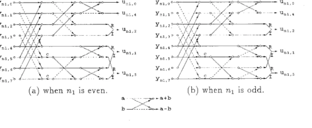
(a) when n1 is even. ( h ) when n1 is odd.
- a + b
:XL
Figure 2: Stage 1 - Pre-addition
%,,z, %,,l, and u,,,S; Stage 2 - Complex D C T and post-a.ddition: computing
the summation of n1 and (5).
T h e Stage 1 for realizing pre-addition is shown in Fig. 2, where the t e r m W8 (=1/&) requires two multiplications for each nl and both architectures for even n a n d odd n are somewhat different. In Stage 2, firstly consider
Uk,,a,
ukl/l, and
&..,S.
In the three cases, the inputs belong complex number, and the computations can be concluded as:7
U k , , k , ? L , , , k 2 W ~ ~ 1 t 1 " k 1 t k 2 ' ~ w h e r e k2 1 1, 2, 5. (10)
nl=ll
This equation is like 1-D D C T , except the input is complex number and the t e r m (IC1
+
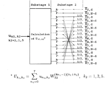
IC;?) is not in the range from 0 t o N ~~ 1. Fig. 3 ( a ) implies the computations of u k l , k 2 with k z = 1 , 2, 5, and which leads t o Yk,,h, for all hia n d ICz= 2, 6, 1, 7, 5, and 3 from (5). In this figure, the first substage is t o
realize
Ukl,k2,
and the second substage is t o realize the post-a.dder.Since u,,,o a n d u,,,4 are real number, we can use the same architecture in
Fig. 3(a) together with the third substage, as shown in Fig. 3 ( b ) , to derive
Yk,,O
and Yk1,4 for allkl
directly by setting the input to beBetween the Stage 1 and Stage 2, the interconnection is not loca.1, b u t it is still regular. This feature of regularity will be utilized t o fold the architecture in the next subsection. T h e following Sta.ge 2 needs four &point complex DCT's with different I C z , and four same butterfly modules. Only the corn-
putation of Ykl,kz with k;?=o,4 requires a.n additional butterfly sta.ge. This reveals t h a t the structure is more regular than [4].
~ j u , , , 4 .
Folding
t h e Parallel Architecture
of
8 x 82-D
I D C T
unl,k2- k2=2,1,5
Substage 11 Substage 2 I
o ~ _
~-
qGal CUI ation
YO,d Y0,N-d Yl,d yl, N-d Y2.d y2, N-d Y3.d y3; N-d Y4,N-d Y5,d y5, N-d Y6,d y6, N-d Y7,d yl, N-d Y4,d
(a) Computation of y k , , k 2 for all k l and k 2 = 2 , 6 , 1, 7 , 5, a.nd 3.
Substage 1 Substage 2 Substage 31
C a l c u l a t i o n
(b) Computatiim of Y k l , k z for all k l and kz= 0 and 4. Figure 3: Stage 2 - Computation of Y k l , k z .
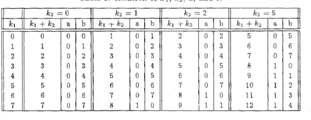
Table i: Relation of Icl, Icz, a, and b.
Before folding the architecture] let’s consider the computation of U,, , k z Ic2= 0, 1, 2, 5. If the index IC1
+
Icz
is replaced by 8a+
b, both a and b areinteger, a n d 0
5
b5
7, then we can derive7
nl=ll
T h e relation among k l , k ~ , a, and b is illustrated in Table 1. Therefore, the computation of U t l , k z can be achieved by the following three steps:
Step 1: Calculate the summation of n1 in (11) for the values of b from 0 to 7. T h e output is denoted by U,
Step 2: T h e output
IT*
from step 1 is multjplird b y 1 or -3 according t o the value of a. For example, in the case of k z = 2 , the output needs to be multiplied by - j when b=O, 1.Step 3: T h e output from step 2 is rotated t o make the output order t o be the increasing order of k l . This step can be implemented by a barrel shifter.
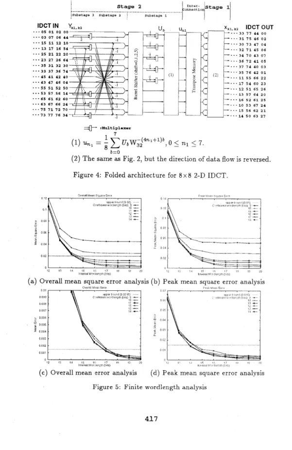
We then fold the structure and reverse the d a t a flow to obtain the archi- tecture of 8 x 8 2-D IDCT. T h e folded architecture is described in the Fig. 4 Among the four sets of the input, only the first set needs to pass through the Substage 3, so the multiplexers a t the end of this substage can select the correct d a t a t o t h e next substage. T h e Substage 2 is similar t o Fig 3, but the direction of the d a t a flow is reversed. T h e Substage 1 includes a barrel shifter,
a s e t of multiplexers to select whether the d a t a multiplying - 3 or not, and a
complex IDCT: un, =
xi=D
UbWi$4n1+1)b. For the sake of the regularity of t h e interconnection, the interconnection can be represented by four 4-by-4 transpose memories. Finally, the Stage 1 is obtained by reversing the d a t aT o realize unl in the Fig. 4, we rewrite ub=p+jq, and then obtain
T h i s computation requires two 1-D IDCTs together with 16 additions. There- fore, according t o the Fig. 4 , the proposed design can be implemented using two 1-D IDCTs and one transpose memory, which is just required by row- column design method together with 76 extra adders and 4 extra consta.nt multipliers.
Finite Wordlengt
h
A nalysis
When implementing a n IDCT architecture, there are two inherent errors which will reduce t h e accuracy of outputs; one is quantization error of co- efficients a n d another is finite internal wordlength. Therefore, the Joint C- CITT/ISO committee has established a specification t o evaluate t h e errors caused by finite wordlength in IDCT[6]. According t o this specification, the proposed I D C T architecture requires 10,000 8 x 8 blocks of random number-
s in the range from -256 to 255 as the input. The plots of overall mean square error versus internal wordlength with different coefficient wordlengths are shown in Fig. 5(a). The horizontal dashed line is the upper bound for overall mean square error. Fig. 5(b), (c), and (d) describe the analysis of peak mean square error, overall mean error, and peak mean error, respective- ly. T h e above analysis implies that 11-bit coefficient wordlength a n d 17-bit internal wordlength will be enough t o satisfy the four error requirements.
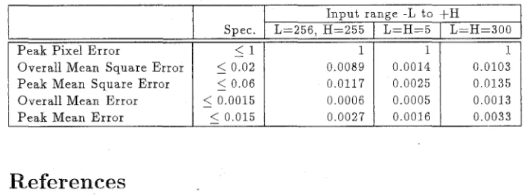
Based on the same analysis, Table 2 shows the results for three different input ranges ([-256:+255], [-5:+5], and [-300:+300], which are also mentioned by Joint CCITT/ISO) with 12-bit coefficient wordlength and 18-bit internal wordlength. It is clear that d l the values are much smaller than the specifi- cations except for the overall mean error a t the range of [-300:+30L'].
CONCLUSIONS
This research analyzes the N x N 2-D D C T / I D C T using direct method a n d develops a regular architecture. After folding the architecture, it will be very suitable for VLSI implementation. Traditionly, direct method has less computation complexity but irregularity; on the other hand, the row-column method is more regular with the penalty of requiring more computations. However, t h e proposed archit,ecture has both the advantages of low computa- tion complexity and high regularity. According to the specification by Joint CCITT/ISO committee on the IDCT, the proposed design needs only coeffi- cient wordlength of 1 2 bits and internal wordlength of 18 bits.
Table 2: Accuracy Analysis for Three Difference Input Ranges
P e a k Pixel E r r o r
I n p u t ranRe
-
-L t o +HSpec. L=256, H=255
I
L=H=5I
L=H=300 - < II
1 1 I 1 I Overall Mean S qua re ErrorP e a k Mean S qua re Error Overall Mean Error P e a k Mean E r r o r 5 0.02 0.0089 0.0014 0.0103
5
0.06 0.0117 0 . 0 0 2 5 0.01355
0.0015 0 . 0 0 0 6 0.0005 0.00135
0.015 0.0027 0.0016 0.0033References
113 D. Slawecki and W. Li,“DCT/IDCT processor design for high d a t a rate image coding,” IEEE Trans. Circuits Syst. Video Technol., vol. 2, pp. 135-146, J u n e 1992.
[a]
A. Madisetti and A . N. Willson, “A 100 MHz 2-D 8 x 8 D C T / I D C T processor for HDTV applications,” I EEE Trans. Circuits Syst. VideoTechnol., vol. 5, pp. 158-165, Apr. 1995.
[3] P. Duhamel a n d C. Guillemot, ‘LPolynomial transform computation of 2-D D C T , ” in Proc. ICASSP’90, pp. 1515-1518, Apr. 1990.
[4] N. I. Cho a n d S . U . Lee, “Fast algorithm and implementation of 2-D discrete cosine transform,” IEEE Trans. Circuits S y s t . , vol. CAS-38, p- p. 297-305, Mar. 1991.
[5] B. G. Lee, “A new algorithm t o compute the discrete cosine transform,”
I EEE Trans. Acust., Speech, Signid processing, vol. ASSP-32, p p . 1243- 1245, Dec. 1984.
[6] ISO/IEC J T C l / S C 2 9 / W G 1 0 , J P E G Committee Draft
CD
10918, 1991. [7] N. Weste and K . Eshraghian, Principle of CMOS VL SI Design, A Sys-IDCT IN Yk1,,, - - - 0 5 0 1 02 00- "'15 11 12 10 * * * 1 3 17 16 54 * * - 2 5 21 22 20
.
* * 23 17 26 64 * * * 3 5 31 32 30...
33 37 36 14 .. .45 41 42 40 * * * 43 47 46 04 - * * 5 5 51 52 50 *-
53 57 56 14...
65 6 1 6 2 60-
* f 63 67 66 24 - - - 7 5 71 72 70 * * * 7 3 7 7 76 34 =#- :Multiplexer+
r
X,, IDCT OUT --'** 33 77 44 00 ...31 15 46 02I--.
...
...
30 3 4 32 7 3 7 0 7 1 43 45 47 06 01 04 --'... 36 7 2 41 05 .*.37 7 4 40 03 - - - 3 S 76 42 0 1...
11 5 5 66 22 + * * . 17 S 4 60 23 -..-12 5 1 65 26 13 57 6 4 2 0...
16 52 61 2 5 10 53 67 24 15 56 62 21...
14 50 63 27 ... ......
1 (1) U,, = - UbW;J4nl+1)b, 05
77,l5
7. b=O 8(2) T h e same as Fig. 2, but the direction of d a t a flow is reversed. Figure 4: Folded architecture for 8 x 8 2-D IDCT.
Overall mean square error analysis
Overall M ? w Emir 0 01 0 000 O O O R 0 007 0 o o i 0005 0 004 0 002 0002 0 0 0 1 0 0 1 4 0 1 2 12 -"- 1:
-
i 4 t 0 1 0 OL 0 0' 0 C'l 0 02,
(b) Peak mean square error analysis r - IM E,, I
(c) Overall mean error analysis (d) Peak mean square error ana.lysis