Design of Multicode CDMA Systems for 3-D
Stereoscopic Video over Wireless ATM Networks
Po-Rong Chang, Member, IEEE, Chin-Feng Lin, and M. J. Wu
Abstract—This paper investigates the application of multicode
spread-spectrum code-division multiple-access (SS-CDMA) tech-niques to three-dimensional (3-D) stereoscopic video transmission over wireless asynchronous transfer mode (ATM) networks. Three-dimensional visual communications, made through the use of stereoscopic images, are able to achieve total display realism. Such services allow users to share the virtual reality (VR) world without any geographical restrictions. In order to create a 3-D system with two images (left and right) that should be transmitted over a bandlimited mobile channel simultaneously, a cost-effective Motion Picture Experts Group (MPEG)-based wavelet multires-olution coding with a joint motion and disparity compensation is developed to reduce a large amount of information contained in the images to meet the low-transmission rate limitation of mobile channels. However, the rapidly variable bit rate (VBR) charac-teristics of the MPEG-based 3-D videos seems a weakness to the transmission of such videos via a constant bit-rate (CBR) mobile channel. The ATM technique is especially well suited for VBR MPEG-based 3-D video because of its ability to allocate bandwidth on demand to these services. However, since the mobile radio has a limited channel capacity, the overall capacity of the traditional ATM-based SS-CDMA system may not be sufficient to accommo-date the MPEG-based 3-D video services requested by the multiple mobile users simultaneously. To tackle this difficulty, a multicode CDMA technique is proposed to provide VBR MPEG-based 3-D video services by varying the number of spreading codes assigned to the 3-D video to meet its dynamic throughput requirement. Powerful forward error correction (FEC) codes are necessary to protect the video data so that it can be successfully transmitted at an acceptable signal power level. Two separate FEC code schemes are applied to the header and payload of an ATM cell containing 3-D video data, respectively. The ATM cell header is protected by a relatively powerful FEC code to ensure correct delivery and low cell loss rate (CLR). On the other hand, the ATM cell payload is encoded for varying degrees of error protection according to the priority of the payload data in 3-D videos. An adaptive FEC code combining scheme is proposed to provide the good protection for payload data with the maximization of its code rate to minimize the extra bandwidth for FEC overhead.
Index Terms—Multicode CDMA, 3-D video, wireless ATM.
I. INTRODUCTION
I
N THE NEAR future, third-generation (3-G) mobile communications based on the asynchronous transfer mode (ATM) are developed to support a wide variety of multimeda services with diverse statistical characteristics and quality of service (QOS) requirements at cell and call levels. AmongManuscript received August 5, 1997; revised May 5, 1999. This work was supported by the National Science Council, Taiwan, R.O.C., under Contract NCS 88-2213-E009-128.
The authors are with the Department of Communication Engineering, Na-tional Chiao-Tung University, Hsin-Chu, Taiwan, R.O.C.
Publisher Item Identifier S 0018-9545(00)02551-2.
the various kinds of services, video service is becoming an important component of multimedia communication. In this paper, we are particularly interested in three-dimensional (3-D) stereoscopic video. One could acquire the 3-D video by wearing a portable stereoscopic eyeglasses with wireless communication capability. Stereoscopic image display is a simple and compact means of portraying depth information on a two-dimensional (2-D) screen. The binocular parallax or disparity between two images of the same scene, shot from two nearby points of view, contains information about the relative depths of the objects in the scene. Two pictures acquired in this manner form a stereopair. This relative depth can be deduced by humans, when each eye is presented with its corresponding image. In other words, the sense of stereovision can be simulated by acquiring these two pictures of the same scene with the disparity and by presenting the left picture to the left eye and the right picture to the right eye. Thus, stereoscopic image transmission requires twice the conventional monocular transmission bandwidth. However, several schemes [1]–[4] have been developed to exploit the disparity relation to achieve compression ratios higher than that obtained by the independent compression of the two pictures.
In order to further increase the compression ratio, in this paper, we apply the mixed-resolution coding technique [1] to incorporate with the disparity-compensated stereoscopic image compression. The mixed-resolution coding is a per-ceptually justified technique that is achieved by presenting one eye with a low-resolution picture and the other eye with one high-resolution picture. Psychophysical experiments [1] have shown that a stereo image pair with one high-resolution image and one low-resolution image provides almost the same stereoscopic depth to that of a stereo image with two high-resolution images. By combining both the mixed-res-olution coding and disparity-compensated techniques, one reference (left) high-resolution image sequence can be com-pressed by a Motion Picture Experts Group (MPEG)-based motion-compensated discrete consine transform (DCT) scheme independent of the other (right) image sequence. By performing low-resolution disparity-compensated technique, the disparity is able to predict the low-resolution right image sequence from the left image sequence at a lower resolution using the disparity relation. The low-resolution images are obtained using the well-known novel wavelet decomposition [5], [6]. The another advantage of the wavelet decomposition is that it is very suitable for image compression. After the wavelet decomposition, an image is divided in several layers with different importances. Subimages at different layers correspond to different resolutions and different frequency ranges, which 0018–9545/00$10.00 © 2000 IEEE
match the frequency-selected properties of human visual system. The wavelet low-resolution subimage in the left image is encoded by a well-known motion-compensated DCT scheme called the MPEG phase 2 (MPEG2) compressed video [9] since its characteristics are quite similar to the original image. In addition, the other high-frequency wavelet detail subimages in the left images are encoded by a motion-compensated scheme with a multiresolution scalar quantizer, where each quantization level corresponds to a detail subimage at its corresponding resolution level. On the other hand, the right image can be reconstructed from the left image by using the wavelet-based disparity-compensated technique. Since the estimation of both the motion vector and disparity is the computational burden of the joint motion and disparity-compensated technique, we apply the variable block-size multiresolution block matching method [3] to reduce their computational complexity. Both the estimated motion vector and disparity are then differential pulse code modulation (DPCM) coded, and all quantities are entropy coded prior to the transmission.
The ATM technology utilizes the nature of the traffic to effec-tively allocate the network resources via statistical multiplexing. Recently, wireless ATM has become an important research topic over the last three years [10]–[12]. Such services allow users to share novel multimedia applications without any geographical restrictions. J. Zhang et al. [13] have investigated an applica-tion of wireless ATM techniques to the transmission of MPEG video. However, they did not consider the problem of transmit-ting high-variable bit-rate (VBR) MPEG-based 3-D video over a narrow-band wireless channel. This problem could be ame-liorated via multicode code-division multiple-access (CDMA) transmission [8], [14]–[16]. In other words, high data transmis-sion rates are achieved by allocating more than one spreading code to a single MPEG-based 3-D video in order to create more than one virtual channel for the 3-D video. The code number as-signed to each 3-D video is proportional to the dynamic source bit rate of 3-D video. Therefore, a spreading code assignment mechanism has been proposed to assign an appropriate code number to each 3-D video in order to achieve the maximum re-source utilization. Furthermore, in order to avoid the self-inter-ference that a 3-D video employing multiple codes may incur, the multiple codes to/from one 3-D video should be made or-thogonal. This particular spreading coding scheme is called the concatenated orthogonal/PN spreading code [15] which is ca-pable of subdividing a high rate stream belonging to a 3-D into several parallel lower basic bit-rate streams without self-inter-ference. In addition, the quality of received 3-D video may de-grade severely when the ATM cell loss occurs due to the mul-tipath fading, interference, and channel noise. In Section IV, an adaptive forward error control (FEC) code combining scheme has been proposed to eliminate the cell loss according to both the statistical behavior and the importance of data in 3-D video. The objective of code combining is to maximize its code rate and to provide good error protection with reasonable delay. Simula-tion results show that this FEC code combining scheme is able to protect the 3-D video data and achieve the good received pic-ture quality without a large amount of extra FEC overhead data. Moreover, Zhang and Lee [13] have shown that the error con-cealment techniques are very effective in improving both
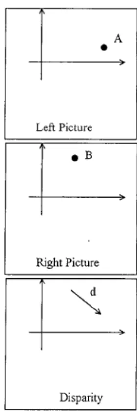
objec-Fig. 1. Stereo disparity: A and B are matching points in the stereopair and d Id the disparity vector.
tive and subjective quality of received MPEG video via multi-path fading channels. Therefore, in Section VI, a modification of both the spatial and temporal error concealment techniques [18]–[23], [35] is applied to recover the left picture in 3-D video with information loss. Moreover, a disparity error concealment technique is proposed to recover the damaged right image. Fi-nally, a typical 3-D video test sequence is conducted to verify the effectiveness of the proposed ATM-based multicode CDMA system in various aspects.
II. STEREOSCOPIC IMAGECOMPRESSIONUSING MIXED-RESOLUTIONCODINGTECHNIQUES
A. Theory of Stereovision
The sense of stereovision is normally simulated by viewing a true 3-D scene. It is possible to stimulate the sense of stere-ovision artificially by acquiring two pictures of the same scene from separated positions and by presenting the left picture to the left eye and the right picture to the right eye. Two pictures ac-quired in the manner form a stereopair. One of the most impor-tant ideas in the study of stereopairs is that of disparity. Fig. 1 illustrates the concept of disparity. Given a point A in the left picture, its matching point B in the right picture does not in gen-eral lie directly underneath A. The vector connecting B to A has been called the disparity, the stereo disparity, the binocular dis-parity, and the binocular parallax of the point pair (A, B). The disparity associated with the point pair (A, B) consists of two components: a horizontal component and a vertical compo-nent . Depending on the camera geometry being used, each component of the disparity can be either positive or negative. When negative disparity occurs, the scene being viewed will
appear to be floating in the space between the viewer’s eyes and monitor. This type of imagery cannot be produced without the aid of stereoscopic devices such as shutter glasses. For another case of parallel axes camera geometry, the vertical component of disparity is always zero and the horizontal component of the disparity is always positive. This implies that the parallel axes geometry processes a simple mathematical relationship between the disparity of a point pair and the distance to the object it rep-resents. In general, the disparity vector can be used to predict one image of stereopair from the other. For example, given a luminance level of the left picture at a position the luminance level of its corresponding right picture can be calcu-lated as
(1) where denotes the disparity vector whose direction is from left to right.
B. Mixed-Resolution Coding for Stereopair Data Compression Using Wavelet Multiresolution Techniques
Mixed-resolution coding is a perceptually justified technique for compressing stereopairs. The compression is achieved by presenting one eye with a low-resolution picture and the other eye with a high-resolution picture. Psychophysical experiments [1] have shown that a stereo image with one high-resolution image and one lower resolution image is sufficient to provide almost the same stereoscopic depth as that of a stereo image with two high-resolution images. Thus, the eye/brain can easily fuse such stereopairs and perceive depth in them. In summary, the concept of mixed-resolution technique can be symbolically represented by the following:
(Stereo image) (High-resolution left image)
(Low-resolution right image) (2)
(LR right image) (LR left image) (Disparity between
both LR images) (3)
where LR denotes the low-resolution image. From the above discussion, the mixed-resolution coding is able to significantly reduce the bit rate required to transmit a stereo image with two high-resolution images. To implement the mixed-resolution coding, one of the novel techniques is based on the well-known wavelet multiresolution signal representation [5], [6]. In the remainder of this section, we would give a brief review on the wavelet multiresolution technique.
Mallat [6] showed that the 2-D wavelet at a given resolution can be completely represented by three separable orthog-onal 2-D wavelet basis functions in : 1)
; 2) ; and 3)
, where and are shift parame-ters for and directions, respectively. The one-dimensional (1-D) wavelet is defined by
(4)
where is the mother wavelet, is a scaling parameter and is a shift parameter, and the 1-D scaling function is defined by
(5) whereφis the mother scaling function. Hence, a 2-D wavelet transform of image between the scale and can be represented as a sequence of subimages
(6) where is the approximation of image at the lowest resolution and the detail subimages at resolution are defined in terms of an inner product
(7) The 2-D separable wavelet decomposition can be implemented first in columns and then in rows independently by using the
high-pass filter and the low-pass filter
, respectively. This decom-position provides subimages corresponding to different reso-lution levels and orientations with resoreso-lution depth More-over, Zhang and Zafar [5] have shown that the decomposed image forms a pyramid structure up to layers with three de-tail subimages in each layer and one lowest resolution subimage on the top. The pyramid structure of the 2-D wavelet decompo-sition with resolution depth three consists of a total of seven
subimages . The resolution
decreases by a factor of four (two in the horizontal direction and two in the vertical resolution) with each layer increased.
After the wavelet decomposition, an image is divided into several layers with different importances. Subimages at different layers correspond to different resolutions and different frequency ranges, which match the frequency-selected properties of the human visual system. It is well known that human viewers are more sensitive to lower frequency than higher frequency image components. Additionally, energies after wavelet decomposition become highly nonuniform. The higher the layer is, the higher the energy becomes. For ex-ample, over 80% of the energy is concentrated in the subimage . For the implementation of mixed-resolution coding, the low-resolution right image can be obtained by performing the wavelet decomposition. However, in order to further achieve the higher compression ratio, the next section will present a new disparity-compensated multiresolution coding scheme which is able to compress the stereo image by aid of low-resolution disparity estimation.
III. JOINTMOTION/DISPARITY-COMPENSATEDWAVELET MULTIRESOLUTIONCODING FOR3-D STEREOIMAGE
SEQUENCECOMPRESSION
This section presents a joint motion/disparity-compensated wavelet multiresolution coding for 3-D stereo image sequence to achieve the higher compression ratio. The left image se-quence (reference image sese-quence) is compressed independent of the right image sequence using a combination of discrete
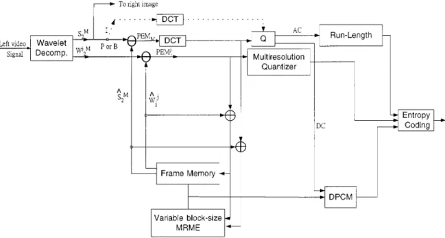
Fig. 2. Interframe MPEG-based hybrid motion-compensated DPCM/DWT/DCT scheme for left image sequence using a variable block-size multiresolution motion estimation (MRME).
wavelet transform (DWT) and MPEG-based motion-compen-sated DCT coding [5], [9]. Instead of transmitting the right image directly, a new interview hybrid DPCM/DWT with scalar quantization (SQ) is proposed to provide the coding information of both the disparity and the prediction error (residual) image to reconstruct the right image from the left image at the receiver. Moreover, by employing the mixed-res-olution psychophysical experiments, one may perform the coding mechanism in the low-resolution manner, where the disparity is estimated from both the left and right images at a low-resolution level and the prediction error image is also obtained by the interview DPCM/DWT/SQ scheme from the low-resolution disparity-compensated right image.
A. MPEG-Based Hybrid Motion-Compensated
DPCM/DWT/DCT Coding Scheme for Left Image Sequence
The left image stream is compressed using the hybrid DPCM/DWT/DCT scheme illustrated in Fig. 2 independent of the right image stream. Using wavelet decomposition, an orignal image is first decomposed into a subimage at the lowest resolution level and 3 detail subimages Since the statistics of the subimage at the lowest resolution are quite similar to the statistics of the original image, an MPEG-based mo-tion-compensated DCT coding technique is used to encode it. Three main picture types are generated from the MPEG coding mechanism. Intrapictures (I-pictures) are coded using DCT transform without reference to other pictures. The I picture at the beginning of a group-of-pictures (GOP’s) serves as a basic entry point to facilitate random seek and also provides the coding robustness to transmission error, but is coded with only moderate compression to reduce the spatial redundancies. Predictive (P) pictures are coded more efficiently using motion-compensated prediction from past
I or P pictures and generally used as a reference for further prediction. Bidirectionally predictive (B) pictures provide the highest degree of compression, but require both past and future reference (I or P) pictures for motion compensation. For either the P or B frames, its prediction error image PEM is encoded using DCT transform and would then be used to obtain the motion-compensated subimage at the lowest resolution, i.e., On the other hand, prediction error subimages
PEM are generated from
their corresponding detail subimages
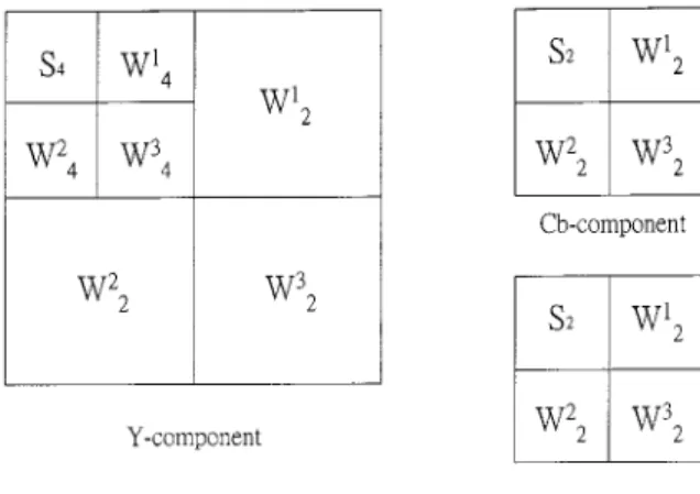
, where each of them is encoded using a scalar quantizer with a quantization level corresponding to its resolu-tion. Such a quantization scheme is called the multiresolution quantizer. These prediction error subimages are then applied for the construction of the motion-compensated detail subimages Moreover, the motion vectors are DPCM coded, and a variable-length coding (VLC) is used for all the quantities including I frame and prediction error subimages. For color video frames, the motion vectors obtained from the luminance component of the color video frames are used as the motion vectors for both the C and C components because component contains more than 60% of total energy in the original image. In this paper, the luminance component is decomposed into seven subimages. In the mean-time, each chrominance component may be decomposed into four subimages since the size of either C or C component is 1/4 of the original video frame size. The resulting subimages are illustrated in Fig. 3.
B. Interview Disparity-Compensated Hybrid DPCM/DWT/SQ Scheme
The aim of disparity estimation is the matching of corre-sponding picture elements in the simultaneous 2-D pictures of the same 3-D scene, viewed under different perspective angles.
Fig. 3. Wavelet decomposition of color image.
Two of those pictures may be the left and right views of a stereopair. A number of block-based disparity-compensated methods have been proposed for thecoding stereopairs [2]–[4]. With block methods, it is assumed that the disparity between the left image and right image is constant within a small 2-D block of pels (pixels). Therefore, the disparity can be estimated by minimizing the norm of disparity prediction error such as
DPE (8)
Consider a block of pels centered around pel in the left image (reference image). Assume that the maximum horizontal and vertical disparity displacements are pels and pels, respectively. Thus, the search region in the right image
would be an area containing pels. A
simplified version of the criterion of (8) is given by DPE
(9)
where and and are
the and coordinates of respectively. The minimization of the disparity prediction error of (9) is performed using any one of the four promising methods used in motion estimation, i.e.: 1) full search; 2) 2-D logarithmic search; 3) three-step search; and 4) modified conjugate direction. According to the mixed-resolution psychophysical experiments, the block-based disparity estimation is performed at the low resolution. The computational complexity of the low-resolution disparity estimation becomes smaller due to the smaller search area at the lowest resolution. At the receiver, the low-resolution right subimage is estimated using the disparity from the low-reso-lution left subimage. A full-size reconstruction is obtained by upsampling a factor of four and reconstructing with the syn-thesis low-pass filter. However, in order to further improve the reconstruction quality of low-resolution right image, disparity has to be transmitted, together with the reconstruction error. In this section, we present an interview disparity-compensated hybrid DPCM/DWT/SQ scheme (shown in Fig. 4) to both
improve the reconstruction image quality and achieve the higher compression ratio.
An original right image is first decomposed into a number
of subimages Only
the lowest resolution subimage is considered in our system. After using the block-based disparity compensation scheme, the disparity-compensated right subimage is estimated from its corresponding low-resolution left images using the low-resolution disparity. Then the lowest resolution prediction error subimages PED for the disparity-com-pensated subimage is formed using the disparity compensation. Since all the pixels in PED are uncorrelated, it is suggested that the lowest resolution reconstruction error subimage PED is coded using an optimal Lloyd Max scalar quantizer (SQ) instead of DPCM. Finally, disparity vectors are DPCM coded, and all the quantities are entropy coded prior to the transmission.
C. Multiresolution Estimation for Motion/Disparity Vectors
Stereo image sequence processing requires the estimation of the displacements created by the motion of objects and also by the disparity between two views of the 3-D scene projected on the two images. The estimation of both the motion and dis-parity displacements may be performed separately. The motion estimation problem is similar to that of disparity estimation. The motion vector can be found by applying any one of the promising search methods to the minimization of motion pre-diction error. In order to further reduce both the computational complexity and searching time of above four methods, an ef-ficient hierarchical block matching algorithm [3], [5] has been applied to both motion and disparity estimation, in which agree-ment of a large block is first attained and block size is subse-quently and progressively decreased. One approach to hierar-chical block matching uses multiple resolution versions of the image and variable block size at each level of the pyramid [3], [5]. In a multiresolution motion estimation (MRME) scheme, the motion vector field is first calculated for the lowest resolu-tion subimage, which sits on the top of pyramid [3], [5]. Moresolu-tion vectors at the lower layers of the pyramid are refined using the motion information obtained at higher layers and again propa-gated to the next pyramid level until the high-resolution level is reached. The motivation for using the MRME approach is the in-herent structure of the wavelet representation. MRME schemes significantly reduce the searching and matching time and pro-vide a smooth motion vector field. Moreover, it is well known that human vision is more perceptible to errors in low frequen-cies than those incurred in higher bands to be selective in spatial orientation and position, e.g., errors in smooth areas are more disturbing to a viewer than those near edges. The subimage contains a large percent of the total energy though it is only 1/16th of the original video frame size. Additionally, errors in higher layer subimages will be propagated and expanded to all the subsequent lower layer subimages. To tackle this difficulty, Zhang and Zafar [5] have proposed a variable block-size MRME scheme to take all these factors into considerations.
Similarly, Tzovaras et al. [3] have shown that the above variable block-size multiresolution block matching techniques are also valid for disparity estimation to reduce the amount of
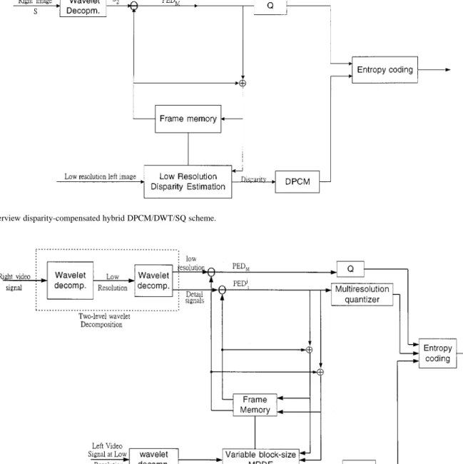
Fig. 4. Interview disparity-compensated hybrid DPCM/DWT/SQ scheme.
Fig. 5. Interview disparity-compensated DPCM/DWT/SQ scheme for low-resolution right and left image sequences using MRDE. processing time. This particular disparity estimation scheme
is called the variable block-size multiresolution disparity estimation (MRDE).
According to the mixed-resolution psychophysical ex-periments and the above concept, this paper presents a low-resolution MRDE scheme for disparity estimation and compensation to improve the computational efficiency of esti-mation. The low-resolution MRDE scheme requires a two-level wavelet decomposition. The first-level wavelet decomposition is used to obtain both the lowest resolution left and right video frames. The second-level wavelet decomposition is conducted to perform the MRDE at the lowest resolution. However, the quality of the reconstructed stereo image sequence may be degraded using only the motion and disparity vectors for some cases. In order to further improve the reconstruction image quality, both the motion and disparity vectors have to be transmitted together with prediction errors.
D. Interview Disparity-Compensated Hybrid DPCM/DWT/SQ Scheme for Low-Resolution Right Image Sequence Using a Variable Block-Size MRDE Technique
All the low-resolution right video frames can be estimated from their corresponding left video frames using the low-res-olution variable block-size MRDE procedure described above. In order to improve the image quality of the reconstructed right video frames, both the disparity and reconstruction (prediction) errors should be transmitted. We use the architecture which is similar to interview hybrid DPCM/DWT/SQ scheme proposed in Section II-B to implement this concept. Fig. 5 shows its basic structure. The main difference between Figs. 4 and 5 is that Fig. 5 contains a two-level wavelet decomposition and a variable block-size multiresolution disparity estimation. Both the lowest resolution left and right video frames are obtained by the first-level wavelet decomposition. The resulting low-resolution left
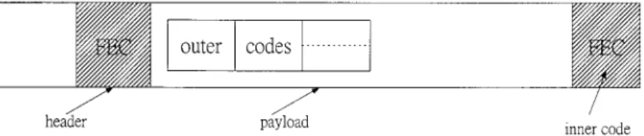
Fig. 6. Logical structure of a wireless ATM cell outer/inner FEC code combining.
and right video frames are again decomposed into the second-level lowest resolution subimage and the wavelets in different scales and resolutions. The second-level prediction error
subim-ages PED PED for
low-res-olution disparity-compensated subimages are formed using the low-resolution variable block-size MRDE scheme. Like the dis-parity-compensated interview compression scheme, the PED is coded using an optimum scalar quantizer, and the subim-ages PED are coded using multiresolution quantizer. For color stereo video frames, the disparity vectors obtained from their lu-minance components are used as the disparity vectors for their
and chrominance components.
IV. DESIGN OFWIRELESSATM CELLS FORMPEG-BASED MULTIRESOLUTION3-D STEREOVIDEOS
This section presents a design philosophy of wireless ATM cells for 3-D stereo videos based on the concept of ATM cell de-sign for MPEG videos. Zhang et al. [13] have proposed a wire-less ATM cell model for MPEG-2 videos which is quite similar to Lei’s cell structure [22] with a header of 5 bytes and a payload of 48 bytes for MPEG-2 over wireline ATM. However, wireless multipath fading, interference, and noise tend to cause signifi-cant ATM cell loss. A single cell loss will result in the severe MPEG image quality degradaion when the cell carries a large amount of payload data. Liu and El Zarki [29] have suggested that the wireless ATM cell should not carry too much data to avoid the loss of large amount of image data in a single cell loss. Furthermore, FEC codes are necessary to protect either the ATM cell header or payload data so that it can be successfully trans-mitted at an acceptable signal power level to provide adequate image quality. However, the extra bandwidth for FEC overhead for wireless ATM cell is also critical in the narrow-band wireless networks. This section will investigate the appropriate tradeoff between forward error control and MPEG-based multiresolu-tion 3-D video transmission quality.
Two separate error control coding schemes are applied to the header and payload of wireless ATM cell illustrated in Fig. 6, respectively. Usually, an ATM cell consists of a 5-byte header. Raychaudhur [8] showed that the ATM header over a wireless nework could be compressed to 2 or 3 bytes. For simplicity, a 2-byte compressed header will be used in the wireless ATM cell. A shortened BCH code of (31,16,3) is suggested to protect this header. On the other hand, a forward error control coding scheme with unequal error protection (UEP) is applied to the payload according to the priority for its data types in 3-D video with a wavelet multiresolution coding. The allocation of priority levels can be performed in a hierarchical multiresolution manner to provide scalable video at different resolutions. There are four
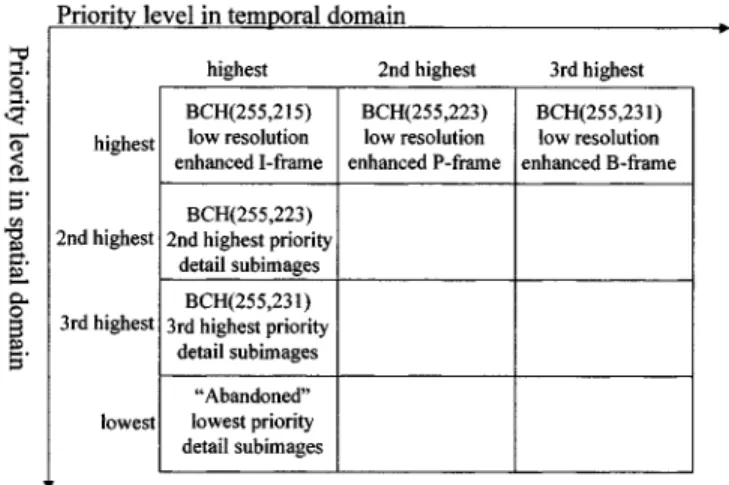
priority levels for the component in the wavelet multireso-lution coding with a seven-subimage decomposition and three priority levels for either C or C component in the wavelet coding with a four-subimage decomposition. For the com-ponent, the encoded bits from the low-resolution subimage could be allocated the highest priority level (priority level 1), three detail subimages , and allocated the second highest priority level (priority level 2), two detail subimages and allocated the third highest priority level (priority level 3), and a detail subimage allocated the lowest pri-ority level (pripri-ority level 4). Since the lowest pripri-ority detail subimage is visually less important than the other subim-ages and has very little impact on video quality, it is not con-sidered in the transmission via the wireless channel. Thus, there are BCH codes with three different error protection levels of (255 215), (255 223), and (255 231) which are used to protect the highest priority subimage ( ), the second highest priority subimages ( ), and the third highest priority subim-ages ( ), respectively. For either the C or C compo-nents, two BCH codes of (255 215) and (255 223) are applied for the protection of the highest priority subimage and the second highest priority subimages ( ), respectively. Its lowest priority subimage is not considered in the trans-mission. From the above discussion, the prioritization of the wavelet multiresolution coding for 3-D video is actually per-formed at the spatial domain. On the other hand, the prioritiza-tion for the multiresoulaprioritiza-tion 3-D video using the MPEG coding mechanism should be also considered in the temporal domain. Especially, there are three priority levels involved in the low-res-olution subimage at three different time points in the tem-poral line since is encoded using the MPEG coding scheme. For the MPEG bit stream generated from the the low-resolution subimage I frame information tends to be the most important data for transmission because the effect of losses on this frame will tend to propagate until the next I frame and then cause no temporal prediction for P and B frames. The P and B frames are, respectively, the medium and the least important data for trans-mission since P frame is usually treated as a reference for the temporal prediction of B frames. Therefore, three BCH codes with three different error protection levels, i.e., of (255 215), (255 223), and (255 231) are used to protect I, P, and B frames at three different time points in the temporal line, respectively. The above joint MPEG source coding and channel coding is also valid for either the C or C components. Next, consid-ering the second highest priority detail subimages in the spatial domain, the essential components in the multiresolution mo-tion-compensated coding scheme become the prediction error subimages PEM PEM and PEM together with their associ-ated motion vectors for the component, and PEM and PEM
together with their associated motion vectors for either the C or C components. It is found that there is no priority difference between any two prediction error subimages located at two dif-ferent time points in the temporal line. In other words, the pri-ority for each prediction error subimage is only considered in the spatial domain. Thus, BCH(255 223) is used to protect those prediction error subimages with the second highest priority (in the spatial domain). Finally, BCH(255 231) is used to protect the lowest priority prediction error subimages, i.e., PEM and PEM for component. However, the lowest priority predic-tion error subimages for both C and C components are not considered in the transmission via the wireless channel. Note that the motion-compensated mechanism for the detail subim-ages is quite similar to the generation of P frames in the MPEG coding. However, it did not include the DCT transform.
As a result, the degree of error protection for the low-resolu-tion subimage should be considered in both the spatial and temporal domains whereas the prediction error subimages are only performed in the spatial domain. Therefore, BCH(255 215) is used to protect the I frame in which is the highest priority subimage in both the spatial and temporal domains. However, the P frame in is the highest priority subimage in the spatial domain, but the second highest priority one in the temporal do-main. Thus, it is protected by BCH(255 223). Similarly, the third highest priority subimage in the temporal domain which is the B frame in could be protected by BCH(255 231). On the other hand, the same error protection scheme can be applied to the de-tail subimages in both the spatial and temporal domains. Fig. 7 shows the basic concept of the priority in both the spatial and tem-poral domains for the MPEG-based multiresolution 3-D video in-cluding the I, P, and B frames generated from the low-resolution subimage (along the temporal line and fixed at the highest priority point in the spatial line) and detail subimages (along the spatial line and fixed at the highest priority point in the temporal line). Note that, for abbreviation, the I, P, and B frames generated from the low-resolution subimage are called the low-resolution I, P, and B frames, respectively. In addition, it is assumed that the iden-tical error protection is applied to any two different picture frames when they have the same priority level in either spatial or temporal domain. For example, the second highest priority low-resolution P frame in the temporal domain and the second highest priority detail subimages in the spatial domain are protected by the same FEC code BCH(255 223). Note that the above-mentioned priority analysis is considered in the frame level. In the meantime, it is de-sirable to consider the priority analysis for the data within each picture frame.
By analyzing the data types in each of I, P, and B frames, it is found that there are eight priority levels for I frame and nine priority levels for either the P or B frames. For the sake of sim-plifying the description and giving a more compact definition for the picture frame in MPEG-based multiresolution 3-D stereo video, it is suggested that each frame may include the disparity information. This particular frame generated from both the left and right low-resolution subimages is called either the low-res-olution enhanced I, P, or B frame at its corresponding time in-stant. Thus, a single low-resolution enhanced frame is able to re-place two picture frames generated from both the left and right low-resolution subimages via the multiresolution
disparity-com-pensated coding scheme. Moreover, the prediction error signals for the disparity-compensated subimages should be considered in the prioritization. For example, the disparity-compensated pre-diction error PED together with the disparity is able to recon-struct the low-resolution subimage in the right image from the low-resolution subimage in the left image. Table I-(A) illus-trates the priority for each data type in either the low-resolution enhanced I, P, or B frame with disparity information generated from the low-resolution subimages in MPEG-based multiresolu-tion 3-D stereo video. For low-resolumultiresolu-tion enhanced I frames, the highest priority is given to the frame header, the second highest priority is given to the slice header, the third highest priority is given to macroblock (MB) header, the fourth highest priority is given to dc DCT coefficients, the fifth highest priority is given to disparity vectors, and the lowest priority is given to high-fre-quency ac DCT coefficients. Correct reception of data types at priority levels 1–4 would guarantee the quality of a low-resolu-tion left image sequence. The quality of right image sequence is maintained at an acceptable level when both the disparity vec-tors at priority level 5 and the data types at priority levels 1–4 have been correctly received. Certainly, correct reception of all the data types would provide the highest 3-D video resolution. For either low-resolution enhanced P or B frames, the fourth, fifth, and sixth highest priority levels are assigned to the motion vectors, disparity vectors, and dc DCT coefficients, respectively, since the availability of partial motion/disparity vector information may be sufficient to produce reasonable low-resolution left and right im-ages, even in the event of absence of DCT coefficient information due to channel losses. Moreover, Table I-(B) shows the priority for each data type in both the second and third highest priority detail subimages with disparity information. Moreover, consid-ering an extension to the above low-resolution enhanced frame, a new abbreviated name called the 3-D enhanced frame containing the low-resolution enhanced frame, disparity information, both the second and third highest priority detail subimages, and the lowest priority detail subimages is proposed to replace in both the left and right image frames belonging to the traditional 3-D video via the MPEG-based joint motion/disparity wavelet mul-tiresolution coding scheme. It yields a complete compact descrip-tion for the MPEG-based multiresoludescrip-tion 3-D video. From the above discussion, the prioritization in MPEG-based multireso-lution 3-D video seems quite difficult because it includes three priority categories, i.e., priority for each 3-D enhanced picture frame in both the spatial/temporal domains and the importance of data types belonging to the frame. Actually, the disparity domain (the fourth priority category) should be considered in the 3-D en-hanced frame. For the sake of simplifying the priority analysis, the third data priority category may include the disparity information via the proposed multiresolution disparity-compensated coding scheme. This would eliminate the complicated priority analysis in the disparity domain. A concatenated FEC coding scheme is pro-posed to overcome this difficulty. The “inner” FEC code is used to protect each frame according to its priority in both the spatial and temporal domains. Undoubtedly, the above-mentioned BCH code for each picture frame is chosen as the best candidate for the inner code. On the other hand, an outer FEC code is proposed to protect the high-priority data within each frame twice in accor-dance with the importance of their data type.
Fig. 7. Inner BCH-coded unequal error protection (UEP) scheme for each MPEG-based multiresolution 3-D enhanced picture frame according to its priority in both the spatial and temporal domains. Note that each of the low-resolution enhanced I, P, and B frames, and the detail subimages with three different priority levels includes the disparity information.
Assume that the frame header is included in a RM (resource management) cell with a high-error protection which is used to provide the current frame information and its resource manage-ment status for mobile receivers before transmitting the ATM cells. Hence, the outer FEC codes are proposed to protect the second, third, fourth, and fifth highest priority data (slice header, MB header, dc values, and disparity) for the low-resolution en-hanced I frames and to protect the second, third, fourth, fifth, and sixth highest priority data (slice header, MB header, mo-tion vectors, disparity, and dc values) for either the low-resolu-tion enhanced P or B frames. Without the outer FEC proteclow-resolu-tion, the remaining low-priority data are still protected by the inner codes. For the sake of reducing the implementation complexity, a class of shortened BCH codes is chosen for the design of the outer FEC coding. In the near future, we will concatenate either the inner rate compatible punctured convolutional (RCPC) code [25] or turbo code [36] with the proposed outer BCH code to further reduce the BER floor. Note that the adaptive outer error code combining is also suitable for the second and third highest priority detail subimages with disparity information according to the priority rank illustrated in Table I-(B). Their second, third, fourth, and fifth highest priority data (slice header, macroblock header, motion vector, and disparity) are protected by the same outer FEC coding scheme. The next section will discuss more details of the code selection principle for outer codes. In sum-mary, Fig. 7 highlights the inner BCH-coded UEP scheme for each 3-D enhanced picture frame according to its priority in both the spatial and temporal domains. Note that the lowest priority detail subimages are not considered in the UEP scheme. On the other hand, Table I shows the priority bank for the data types be-longing to each 3-D enhanced picture frame in accordance with the outer BCH-coded UEP scheme.
A. Code Selection Principle for Outer FEC Codes According to Data Partitioning
The work by Parthasarthy et al. [26] which describes a code selection strategy in the case of a normal RS code scheme for video traffic over wireline ATM networks is the closest to this
TABLE I
PRIORITYRANK FOR THEDIFFERENTDATA
TYPESWITHINEACH3-D ENHANCEDFRAME INMPEG-BASEDWAVELET MULTIRESOLUTION3-D VIDEO
paper. However, in [26], the MPEG video protected by the use of concatenated code according to its priority has not been con-sidered. The objective of code selection is to minimize the outer code overhead and to provide good protection with reasonable delay. In other words, we choose an appropriate class of outer codes which maximizes the average code rate (for a coded ATM cell) given by
(10)
where denotes the average number of message bits in a coded ATM cell and and represent the average numbers of bits in a coded header with BCH(31,16) and in a coded pay-load with inner/outer FEC coding, respectively. The maximiza-tion of is over all the shortened BCH codes. Unfortunately, it is hard to characterize directly in accordance with the vari-able bit rate (VBR) characteristics of the high-priority data be-longing to each 3-D enhanced frame in MPEG-based multires-olution 3-D video. To overcome this difficulty, evaluate the av-erage code rate for each of three essential components in the 3-D enhanced frame, i.e., low-resolution enhanced frame, the second
and third highest priority detail subimages with disparity infor-mation, separately. Moreover, for the sake of simplifying the evaluation of the average code rate, the expression of (10) can be approximated by
Slice
Slice Code ATM (11)
where Slice is the average number of message bits in a slice and Slice denotes the average number of bits in a coded slice using outer coding scheme only. Code and ATM represent the average numbers of bits in the inner code overheads and in the coded ATM headers within a slice, respectively. Let denote the number of message bits in the inner code. In other words, each ATM cell with inner coding can carry message bits per cell. Note that the coded bits generated by outer coding are treated as the message bits for the inner coding. Hence, the av-erage number of ATM cells for a slice is Slice
where denotes the smallest integer which is greater than First, the low-resolution enhanced I, P, and B frames with disparity information generated from the low-resolution subim-ages in both the left and right image sequences are regarded as a typical example to illustrate the evaluation of the average code rate For the low-resolution enhanced I, P, and B frames, it
is found that Code and ATM
where (I frame) or (P frame) or
(B frame). Therefore, the expression of (11) becomes Slice
Slice Slice
(12)
where or or . Note that (12) is also valid
for the second and third highest priority detail subimages with disparity information by employing (BCH(255 223)) and (BCH(255 213)), respectively.
Since Slice is a fixed value independent of outer coding scheme, the maximization of then becomes the mini-mization of Slice The expression of Slice for either the low-resolution enhanced I, P, or B frames with disparity information generated from low-resolution subimages in 3-D video is given by Slice Slice for I frames (13) or Slice Slice for P or B frames (14)
where Slice is the average number of bits in a coded slice header using outer FEC coding. denotes the average number of bits in a coded MB header and is the average number of MB’s within a slice. denotes the average number of bits in the coded dc values in block and repre-sents the average number of blocks in a slice, where or U ( ) or V ( ). is the average number of bits in a coded motion vector and is the average number of motion vectors in a slice. presents the average number of bits in a coded disparity vector and is the average number of disparity vectors in a slice. Note that the above parameters are encoded using outer FEC coding scheme only. Meanwhile, denotes the average number of bits in low-priority ac DCT co-efficients within a slice without outer FEC coding. ,
( ), and represent the average numbers
of bits in the disparity-compensated prediction errors for the and components of the low-resolution subimage in the right image without outer coding, respectively.
For the second highest priority detail subimages with dis-parity information, there are three prediction error subimages PEM PEM and PEM which have the identical size for the component and two prediction error subimages with an iden-tical size, i.e., PEM and PEM for either the or com-ponents. Each macroblock in the second highest priority detail subimages may contain the picture information for these seven prediction error subimages and their associated motion vectors, disparity vectors, and disparity-compensated prediction errors. Thus, the expression of Slice for the second highest priority detail subimages is defined as follows:
Slice Slice
(15)
where and are, respectively, the average
numbers of bits in a coded motion vector and a coded disparity vector for the second highest priority subimages.
and are the average numbers of macroblocks, motion vec-tors, and disparity vectors in a slice, respectively. and denote, respectively, the average numbers of bits in the motion-compensated and disparity-compensated prediction error subimages belonging to a slice. Similarly, the expression of Slice for the third highest priority detail subimages with disparity information is given by
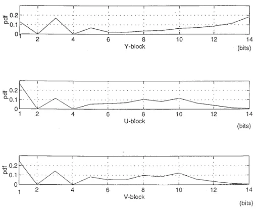
Fig. 8. Data distributions of dc coefficients in Y, U, and V blocks in the I frame generated from the low-resolution subimage in the left image sequence.
Note that the lowest priority subimages are not considered in the calculation of both the and because they are dropped prior to the transmission.
B. Adaptive FEC Code Combining Strategy for Outer Code Combining
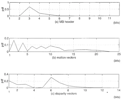
This section presents an adaptive FEC code combining scheme which is able to achieve the optimal outer code selection according to the statistical data distribution of the multiresolution 3-D stereo video source coding. This combining strategy is similar to the concept of Huffman source coding. A typical color 3-D image sequence “Spiral Ball” (size 640 480), in the 3-D library of the 3-D museum constructed by Multimedia Creators Network of Pioneer Electric Corporation, is considered in the design of outer code selection. Two basic shortened BCH codes of (7,4) and (15,7) are chosen as the basic core codes in the outer code combining to minimize the code overhead and also to provide good protection with reasonable delay. A number of low-resolution enhanced I, P, and B frames with disparity information generated from both the left and right image sequences in Spiral Ball using the MPEG-based joint motion/disparity-compensated wavelet multiresolution coding scheme are treated as a typical test video pattern to evaluate the performance of outer code combining. For the sake of describing the characteristics of the low-resolution enhanced frame clearly, we investigate its two essential components, i.e., a pure low-resolution frame generated from the low-resolution subimage in only the left image sequence and disparity infor-mation, separately. Fig. 8 shows the data distributions of dc coefficients in Y, U, and V blocks of the pure low-resolution I frames (without disparity information), respectively. On
the other hand, Fig. 9 illustrates the data distribution for the disparity vectors that are obtained from the low-resolution subimages in both the left and right image sequences when the I frame is generated from the left image sequence at a specfic time instant. It should be noted that the above data distributions are evaluated over all the left and right image frames in the Spiral Ball. Similarly, the data distributions of high-priority data (MB header and motion vectors) in the pure low-resolution P and B frames generated from the left image sequence and their associated disparity vectors are illustrated in Figs. 10 and 11, respectively. The following procedure for encoding dc in the pure low-resolution I frame is treated as a typical example for outer code combining: 1) if dc bits, use BCH(7,4) to encode dc ; 2) if dc bits, use BCH(15,7) to encode it; 3) if dc bits, use BCH(7,4) + BCH(15,7) to encode it; and 4) if dc bits, use 2 BCH(15,7) to encode it. Note that the maximum number of bits in dc is 14. The probability for each data
range can be found as: 1) dc ; 2)
dc ; 3) dc ;
and 4) dc Therefore, the average
number of bits in the BCH outer coded dc belonging to the I frame becomes 19.7725.
Similarly, the same BCH outer code combining can be applied to dc values in both the U( ) and V( ) blocks be-longing to a pure I frame generated from the left low-resolution
subimage. Hence, and
are found to be 40, 10, and 10, respectively. A combining of 6 BCH(15,7) is used to encode a fixed 38-bit slice header with high FEC protection for the I frame. Similarly, a fixed 2-bit MB header is protected by
Fig. 9. Data distribution of disparity vector obtained from the low-resolution subimages in both the left and right image sequences when I frame appears in the left image sequence.
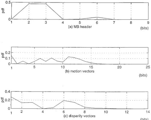
Fig. 10. Data distributions of MB header, motion vectors, and disparity vectors in the low-resolution enhanced P frame.
In addition, and For the
dis-parity information, , , and
From
(13), Slice Moreover, the average code rate
for the ATM cell containing the low-resolution enhanced I frame with disparity information is computed by (12). It yields
For the low-resolution enhanced P and B frames, the same BCH outer code combining scheme is applied to their high-priority data according to their data distribution. However, a combining of BCH(15,7) + 2 BCH(31,16) is applied to the 38-bit slice header of either P or B frames with a medium FEC protection. This leads to Slice The average code rates
Fig. 11. Data distributions of MB header, motion vectors, and disparity vectors in the low-resolution enhanced B frame.
for the ATM cells containing the low-resolution enhanced P
and B frames are found to be and ,
respectively. The outer FEC code combining based on these two basic BCH codes of (7,4) and (15,7) can be also applied for the error protection of either the second or third highest priority detail subimages. This would yield for the second highest priority detail subimages and
for the third highest priority one.
V. TRANSMISSION OFMULTIPLEVIDEOS OVERATM-BASED MULTICODECDMA MOBILECOMMUNICATIONNETWORKS
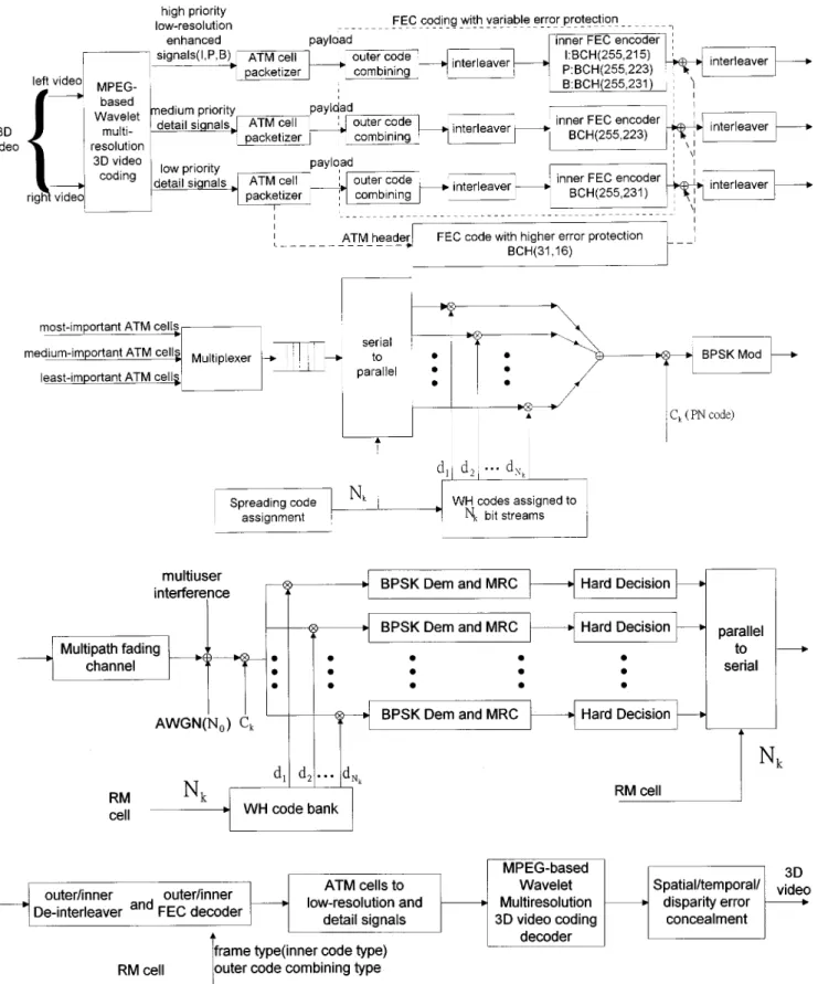
In the near future, the third-generation mobile communica-tion will allow high-mobility users to access video informacommunica-tion stored at various network sites. The multicode CDMA seems one of the major technologies [14], [15] for supporting video services in the third-generation system. In this paper, we are trying to propose a generic multicode CDMA system for pro-viding the transmission of multiple videos via wireless ATM network. For the applications of 3-D stereo videos, Fig. 12 il-lustrates the wireless ATM-based multicode CDMA architec-ture for the transmission of MPEG-based multiresolution 3-D video. Four FEC channel coding schemes are considered in the ATM cell packetizer for the MPEG-based wavelet multireso-lution 3-D video coding. The FEC code with high-error pro-tection is applied to ATM headers. The adaptive outer/inner FEC code combining scheme with variable error protection is used to protect the low-resolution subimages, motion vectors, and disparity vectors according the priority analysis. The same code combining mechanism is also applied to the detail subim-ages. For example, two outer FEC codes with medium- and low-error protection in the code combining scheme are used
to protect the medium- and low-priority detail subimages, re-spectively. The architecture illustrated in Fig. 12 with a little modification is also vaild for different types of video coding schemes, i.e., MPEG-4, H.263, etc. However, the traditional CDMA system may not be sufficient to accommodate the trans-mission of the high-bit-rate videos via a narrow-band mobile channel. In the multicode CDMA system, when the th video needs times the basic transmission rate, it converts the orig-inal high-bit-rate bit stream using a multiplexer or serial-to-par-allel converter into basic rate streams, encodes each with a different spreading code, modulates them with a different Walsh modulator, and superimpose them before upconverting for mo-bile transmission. In other words, each spreading code in the multicode CDMA carries a data stream with a basic rate spreading codes in parallel will provide a single user with times the basic rate capability. Note that each video admitted into the system has a primary PN code assigned to it. These PN codes are not orthogonal between different video users. To avoid the self-interference that a video user employing multiple codes may incur, the multiple codes to/from one user should be made orthogonal. If is the primary PN code of video with a basic transmission bit rate new concatenated spreading codes, can be derived by concatenating with where is the th orthogonal code
and if It should be mentioned that the actual
value of depends on the frame type, frame period, basic transmission rate, desired cell loss, and total number of bits in all the coded ATM cells. A spreading code assignment mecha-nism is proposed to determine an appropriate value of which is able to achieve both the higher transmission capability and better received picture quality. Due to the orthogonality require-ment, the maximum number of orthogonal codes per user is the
Fig. 12. Overall schematics of MPEG-based 3-D video transmission via ATM-based multicode CDMA system resource management (RM) cell contains Nk, frame type, and outer code combining type. Note that the inner BCH codes may be replaced by either turbo or RCPC codes.
ratio between the channel chip rate and the Walsh modu-lator output rate. is termed as the spreading sequence length. Hence, . The above coding strategy is called the sub-code concatenated scheme that orthogonal sequences are
con-catenated with a PN sequence to increase the randomness of the orthogonal sequence. The binary orthogonal sequences used in this paper were the well-known Walsh–Hadamard (WH) codes which have zero cross correlation at zero time delay. They are
used when synchronization of transmission can be maintained. Unfortunately, the multipath fading in a cellular radio environ-ment introduces nonzero time delays that destroy the orthogo-nality between WH codes. Fong et al. [15] showed that a suf-ficiently long PN sequence is concatenated with WH codes to randomize and eliminate their unsatisfactory and inhomogenous behavior at nonzero time delays. The long PN sequence may be chosen as either an sequence or Gold sequence.
A. Multicode CDMA Transmitter Model with Concatenated Orthogonal/PN Spreading Code Scheme
For videos transmitted over a mobile channel, each of them is divided into parallel data streams (virtual chan-nels) for user at time where a specific WH code is as-signed to each virtual channel. The value of is dynami-cally determined by a code assignment mechanism discussed in the next section. For simplicity, is assumed to be a
con-stant in the th time interval i.e.,
for Hence, the total number of codes assigned to all the users in the new time interval is
where denotes the th intersection interval of the time intervals for all the videos, i.e.,
Usually, is a fixed value called the frame
period. Note that WH codes assigned to different users may be identical. It should be mentioned that the above arguments are valid when each user has a continuous video presentation. How-ever, this assumption may not be true since some users may not have videos during a specific time interval, i.e., To tackle this difficulty, the value of for this particular interval is set to zero. Therefore, the above argument become valid again. For simplicity, we assume that each of the videos has its cor-responding picture frames during The transmitting BPSK signal of the th data stream (virtual channel) belonging to the th video during the th time interval is expressed as
(17) where is the transmission power of the base station, is the random phase angle, uniformly distributed between 0 and 2π, introduced by the modulator, and is the data signal which consists of a sequence of rectangular pulses of duration
i.e.,
(18)
where and is a unit pulse function of
duration The concatenated spreading code can be ex-pressed as
(19)
where is the concatenated spreading sequence
which is equal to the product of a PN sequence used by the th user and a code sequence
assigned to its th virtual channel. The duration of each data
bit is while the duration of each chip in the spreading code
is The number of chips per bit is where is
an integer. The period of the WH code sequence is equal to the processing gain The long PN sequence has a period, that is much greater than Moreover, and are chosen to be relatively prime so that every possible chip of the PN sequence can occur at the beginning of some data bit. As a result, the total signal transmitted to users is
(20)
B. Mobile Radio Channel Model
The Rayleigh multipath fading model is the general accepted channel model for mobile communications [27]. In this paper, we adopted the Rayleigh fading model for performance analysis in our multicode CDMA system. The channel impulse response for the th virtual channel of the th user is given by
(21) where is the th Rayleigh distributed random path gain, is the th random path phase, uniformly distributed be-tween zero and 2π, and is the th uniformly distributed random delay ranging from zero to one data bit period represents the unit impulse function. denotes the number of resolvable multipaths for the th virtual channel of user In addition, it should be mentioned that these channel parameters vary with the transmitter–receiver distance. It may be shown that
and for
since all the parallel virtual channels introduced by the same user are transmitted over the same propagation environment be-tween the transmitter and receiver and then would have iden-tical channel characteristics, where denotes the variance of a random variable
C. Receiver Model
The received signal at the input to the matched filter in the mobile receiver is given by
(22)
where is the complex envelope of denotes the
real part of complex number, and is a white Gaussian noise with two-sided power spectral density
For simplified analysis, the first virtual channel of the first user is chosen as the reference for calculating the probability of error of its data symbol in the th sampling time interval The receiver is able to coherently re-cover the carrier phase and locking to the th path as
a reference path between the transmitter and its corresponding receiver. All other paths constitute interference. That is, we
as-sume without loss of generality that and The
envelope of the matched-filter output at the th sampling time instant ( ) is denoted by and can be expressed as
(23) where
(24) Int is the intramultiuser interference (self-interference) in-dicating the interference introduced by the other virtual chan-nels of reference user, Int is the intramultipath interference, and Int denotes the inter multiuser interference. Note that the orthognality of the concatenated spreading codes eliminates the intramultiuser interference (self-interference) [15]. This leads to Int
D. Calculation of Average Cell Loss Rate
This wireless ATM cell is transmitted over the wireless CDMA link. Assuming that bit synchronization and cell synchronization have been achieved, the mobile receiver first decodes the ATM header. If the cell is successful, the receiver then decodes the payload. There are two major factors that cause wireless networks to discard ATM cells. One is bit errors in the header due to the multipath fading, interference, and channel noise. The other is buffer overflow in multiplexing or cross-connecting equipment. The cell loss process due to buffer overflow can be approximated by a two-state Markov chain called the Gilbert model [28]. Here, for simplicity, we only consider the cell loss due to the bit errors on the header. Usually, a single cell loss may cause a loss of an amount of image data and results in a high degradation of picture quality. Moreover, the picture is still corrupted by the multipath fading, interference, and noise even if the ATM cell is successful. Fortunately, this picture degradation can be eliminated by using the proposed FEC code combining strategy, spatiotemporal fil-tering [31], and spatial/temporal error concealment techniques. Therefore, the cell loss rate (CLR) is regarded as the major performance index used to evaluate the quality of received picture. For the simplified derivation of the CLR, the Gaussian assumption is to take all the self-interference, intramultipath interference, and intermultiuser interference terms as Gaussian noise. In addition, since all the signals including the desired signal and the interfering signals caused by the other
users relative to reference user (user 1) are transmitted to the first mobile receiver from the same base station (downlink) and have the identical propagation environment between the base station and the receiver for user 1, it can be shown that
and Let represent the
receivied signal energy per bit via the th path (reference path).
Thus, the received signal is found to be Moreover, according to the orthogonality of the concatenated spreading codes, it can be found that the variance of the total interfering
signals is where
and Hence, the average
value of half the signal-to-noise plus interference power ratio becomes
(25) Note that is always greater than one. For simplicity, assume that the path gains for all the virtual channels in the same user are independent identically distributed (i.i.d.), i.e.,
Thus, the value of is identical to
Proakis [27] showed that the BER of a receiver with maximal ratio combining (MRC) of order can be expressed as a form in terms of
for MRC of order (26)
In (26), for maximal ratio combining, the quantity repre-sents the average signal-to-noise ratio per combined path, and Since a BCH code of (31,16,3) is proposed to protect the 16-bit compressed ATM header, the CLR is computed by
CLR (27)
E. Determination of Average WH Code Number for 3-D Stereo Video
The average number of WH codes assigned to a specific pic-ture frame in conventional 3-D stereo video is dependent on the average number of bits in a picture frame the transmission bit rate for a virtual channel (WH code) and the frame period Thus, the average WH code number assigned to the specific frame is estimated by
(28) However, the expression of (28) can be extended to the MPEG-based multiresolution 3-D video coding. From Sec-tion IV, it is known that there are three different ATM code rates,
i.e., and for the low-resolution enhanced I,
P, and B frames with disparity information generated from the low-resolution subimages in 3-D video at three different time points. and correspond to the average numbers of bits in the low-resolution enhanced I, P, and B frames including both the disparity vectors and disparity-compensated prediction errors, respectively. On the other hand, and are, re-spectively, the ATM code rates for the second and third highest priority detail subimages. The average total number of bits in either the second or third priority detail subimages containing
the disparity information is or As a result, the average WH code number assigned to a 3-D enhanced picture frame at a specific time instant is calculated by
(29)
where , , or .
More details of the spreading code assignment mechanism can be found in (38).
VI. SPATIAL, TEMPORAL,ANDDISPARITYERROR CONCEALMENTTECHNIQUES FOR3-D STEREOVIDEO WITH
INFORMATIONLOSS
In this section, we propose the cell loss resilience techniques to conceal the information loss in 3-D stereo video due to multipath fading and interference. For the multiresolution 3-D video coding, the low-resolution subimage in the left image sequence plays an essential role in the picture quality of received 3-D video since the high-frequency detail subimages are visually less important than the low-resolution subimage and have very little impact on video quality. The low-resolution subimage in the right image subimage may be reconstructed by the disparity-compensated technique. In this paper, the low-resolution subimage in the left image sequence is encoded by using MPEG-2 coding technique. However, Zhang and Lee [17] have shown that the MPEG-2 source coding algorithm is very sensitive to multipath fading channel and interference. For example, a single bit error in the ATM header (cell loss) will often result in loss of a whole image block, which could further cause consecutive block losses. Sometimes, a number of consecutive blocks may be destroyed when a single bit error occurs in either the slice header or macroblock header or motion vector, even though the ATM cell is successful. On the other hand, the ATM cell loss may result in loss of a whole image block in the right image when the cell contains the disparity vector or the control headers related to the disparity.
The cell discarding may also be caused by network con-gestion and buffer overflow [28]. Several methods have been proposed to minimize the effect of cell loss on the received image quality. These schemes include FEC coding with inter-leaving and error concealment using postprocessing methods [18]–[22]. In this paper, we consider the combination of these strategies. The two main cell loss resilience techniques described here are the spatial and temporal error concealment techniques. The spatial error concealment exploits the spatial redundancy in one picture. This technique is proposed for intracoded pictures, i.e., I frame, where no motion information exists. Temporal error concealment makes use of the temporal redundancy in one sequence. It is devoted to intercoded pic-tures, i.e., P and B frames, because there exists some motion information. The temporal error concealment is also suitable for the recovery of the damaged right image with respect to the left image when the temporal information is replaced by the disparity information. It should be mentioned that the spatial/temporal/disparity error concealment techniques are
also applied to the recovery of information loss, even though the ATM cells are successful. For instance, a single bit error in the DCT coefficients may damage one block when the DCT coefficients of each block are coded using run-length and variable-length coding. Moreover, a number of subsequent blocks may be destroyed if a bit error occurs in the macroblock header. Note that the information loss in the detail subimages caused by ATM cell loss did not result in the severe image quality degradation. It only leads to the blurred image quality.
A. Multiresolution Multidirectional Interpolation for Spatial Error Concealment
Since lost blocks are often correlated with neighboring spatial blocks due to the correlation property of nature images, interpo-lation and surface fitting can be used to partially recover the lost information [18], [19]. However, such techniques are low-pass filtering in nature and tend to ignore high-frequency information such as edges and contours. Lee et al. [21] have proposed a fuzzy logic approach to recover the lost blocks with high frequency and yield the desired reconstructed picture quality. Meanwhile, this fuzzy loss recovery technique is too complicated for im-plementation. Therefore, a cost-effective multidirectional inter-polation [20] is employed to conceal the lost block with high frequency, where the damaged block is surrounded by eight neighboring blocks of correctly received pixels. A voting clas-sification mechanism operates on the eight neighboring blocks and determines which directions characterize the three strongest edges. A spatial interpolation is performed to create the recov-ered block for each direction separately. Those interpolation re-sults are then mixed by averaging to obtain the final recovered block containing multiple interpolated edges. The determina-tion of the direcdetermina-tions for the strongest edges depends on ex-tending edges present in the neighboring blocks so that they pass through the damaged block. The direction classification for edges can be performed by a Sobel gradient operator which is able to give accurate angle estimates.
The multidirectional interpolation works well when the an-gular direction of edge is near to one of eight directional cat-egories. However, this method becomes invalid when the edge direction is not close to any directional category. To tackle this difficulty, a multiresolution direction classification is proposed to achieve the more accurate direction estimation. This classifi-cation is a two-level windowing process. The first-level process is the original voting mechanism which provides a coarse esti-mation for the edge direction and then determines the selected nested region between two adjacent direction categories. The second-level process is a fine estimation for the edge direc-tion based on four finer direcdirec-tional categories belonging to the chosen nested region. The difference between any two adjacent finer directional categories is 5.625 . In simulation results, we will compare our multiresolution approach with the original one and show the improvement of our method.
Sometimes, a cell loss may cause a sequence of consecutive horizontal block losses when it contains a slice header, a mac-roblock header, or a sequence of block data. A sliding block iteration method is proposed to conceal the continguous block loss by using the multiresolution multidirectional interpolation block by block. First, the damaged left-most block 0 is recovered