COMBINATIVE MOTION ESTIMATION ALGORITHM AND THE CORRESPONDING
ARCHITECTURE FOR COMPLEX MOTION PHENOMENON
Pei-Chuan Liu, Wen-Thong Chang and Wen-Zen Shen Institute of Electronics
National Chiao Tung University HsinChu, Taiwan, R.O.C.
Abstract
Combining the features of block matching algorithm and block recursive algorithm a new motion estimation method is proposed for complex motion phenomenon. With the full searching procedure used in block matching algorithm and the adaptive searching procedure used in block recursive algorithm, the proposed combinative algorithm can be used to estimate more complex motion parameters such as translation, zoom, rotation and image deformation and get good performance. To reduce the computational complexity, the corresponding architecture of the combinative algorithm is also proposed. With this architecture the computation amount can be largely reduced to make the proposed algorithm can be used for real time motion estimation. I. Introduction
Block matching method [l-21 based on two- parameter motion model has been widely used for motion estimation. In this method the full searching procedure is used to find the best matched blocks between two iterative images in a predefined searching range. Using the full searching procedure the block matching method can get the global minimum solution. However, in many cases, pure translatory motion assumption is not sufficient to describe the image motion phenomenon. For this, the three-parameter motion model [3], the six-parameter affine transform and the eight-parameter bilinear transform [4] have been proposed to describe the more complex motion phenomenon. In these motion models block deformation on block size or block shape is seen. The lack of ability of block deformation makes block matching algorithm hard to be applied for the motion estimation with more complex motion phenomenon.
Block recursive method is an adaptive motion estimation algorithm that combines the block
process concept [5] and the recursive searching procedure. The adaptive searching procedure makes the block recursive method to have the ability of block deformation and so it is suit for complex motion estimation. Based on the block recursive algorithm and the quantized state algorithm [6-71, a quantized block recursive method is proposed to reduce the computational amount with the least performance loss. In spite of having the ability of block deformation for complex motion estimation, because of using the recursive searching procedure, block recursive algorithm meets the local minimum problem [8] and may estimate to get the local minimum solution but miss the global minimum solution.
To solve the local minimum problem, a combinative motion estimation algorithm that combines the features of block matching method and block recursive method is proposed. In this combinative motion estimation method the recursive searching procedure is used for the estimation of complex motion parameters and the full searching procedure is used to solve the local minimum problem. So with the combinative estimation method the block deformation problem and the local minimum problem can both be solved.
Under the consideration of hardware implementation, the large computational amount makes the combinative algorithm hard to be implemented. For this, the architecture design of the proposed combinative algorithm is discussed. In this architecture the computation amount could be largely reduced according to the coordinate relationship. The rest of this paper is organized as follows. In section I1 we f i s t briefly introduce the block recursive method for complex motion estimation. The quantized block recursive algorithm is also derived in this section. After this, the combinative motion estimation algorithm and the performance analysis is derived. For hardware implementation, the corresponding architecture
Contributed Paper
Liu, Chang and Shen: Combinative Motion Estimation Algorithm
and the Corresponding Architecture for Complex Motion Phenomenon 109
design of the proposed algorithm is introduced in section 111. Finally, a conclusion is made in section IV.
11. The combinative motion estimation algorithm
To describe the different motion phenomenon of moving object some motion representation models are proposed. These motion models describe the coordinate relationship before and after deformation. In three-parameter motion model the transformation of the coordinate can be described as
where a, to a, are the current estimates of the true motion parameters cI to ca. G, and Gy are the gradients in X and Y direction.
For N points of signal, Eqn.(4) can be written in a matrix form as
D = G(C
-
A")with
cg are the panning motion parameters to be estimated. In six-parameter motion model the zoom, pan and rotate of object can be described by the affine transformation. The transformation of the coordinate can be described as
In eight-parameter motion model the bilinear transformation of the coordinate can be described as
Besides of the zoom, pan and rotate of object, the image distortion is also considered in the eight- parameter motion model. With this model, the displaced frame difference (DFD) can be described as
( 5 )
where
C = [c,, c2, cg, c4, c5, c6, c7, c , ] ~ is the true motion parameter vector.
A@) = [a,@), a,@), a,@), a4@), a,@), a6@), a7@), a,@)]T is the estimated motion parameter vector at iterationp.
The Block recursive algorithm is to estimate A@) such that E{(IDFDb)l12} is minimized. Based on Eqn.(S) and the steepest descent adaptive algorithm, the block recursive algorithm is derived as
Where E is the convergence factor. To reduce
the computational amount of block recursive algorithm, a quantized block recursive method is proposed. In this quantized algorithm the gradient value is quantized to be number of 2's power and so the multiplication with gradient could be replaced by the shift operation. Also, to increase the stability of algorithm, the compensation for pixel with large coordinate is made to replace the convergence factor E with
L i
(7) To reduce the computation amount the convergence factor is chosen to be number of 2’s power. And so the multiplication with convergence factor could be replaced by shift operation.
Based on the block recursive algorithm in Eqn.(6)-(7) and the block matching algorithm, a combinative algorithm is proposed. In this algorithm, first the block recursive method is used to find the block deformation and the complex motion parameters of moving block and then the block matching method is used to find the global minimum solution. The estimation procedure of the combinative algorithm can be organized as
following :
1. Use block recursive algorithm to find the complex motion parameters. In three-parameter motion model it is to estimate al, a2 and u3. 2. Use the complex motion parameters to find the
shape and size of the deformed block. In three- parameter motion model it is to identify the corresponding points as (x’,, y:) = (alxl+a2,
3. Use block matching algorithm to compare the displaced deformed block with the checking block and find the best matched motion vector
dx
and dy.4. Add motion vector dx and dy to the estimated complex motion parameters. In three-parameter motion model it is to add clx and dy with az and a3 to get the new values of a2 and a3.
alY l+a3).
After proposed the combinative algorithm, the performance comparison of the proposed combinative algorithm with the individual algorithm is made. The image used for simulation is the image sequence “ Football”
.
The block sizeof 16x16 is chosen to be the size of basic block
The searching range of the block matching method is from -8 to 8 and the estimation iteration of the quantized block recursive method is 3. Because there is only zooming effect existing in the image sequence “ Football”, in our simulation the three- parameter motion model is used. To see the effect of zooming motion some slices of picture are skipped and then picture No.1 and No.5 are used
as the reference pictures to get larger zooming effect. The mean absolute value of DFD is used for the judgement of performance. The simulation results are shown in Table.1. In Table.1 it shows the mean absolute value of DFD for blocks in different position with the combinative method, the block recursive method and the block matching method. The corresponding zooming motion parameters are also shown to see the zooming effect of different moving blocks. According to the simulation results it could be found that the performance of the block matching method is better than that of the block recursive method when the zooming effect is not so series. It is because the block matching method uses the full searching process and can get the global optimum solution. With the increase of zooming effect the performance of the block matching method gets worse because of the lack of ability of block deformation. The performance of the combinative algorithm is the best in each case. According to these results it could be found that the combinative algorithm is suit for the motion estimation with complex motion phenomenon and get the best output performance.
111. The architecture design
After made the performance analysis of the proposed combinative motion estimation algorithm, in this section the architecture design of the proposed algorithm is discussed. The architecture of the proposed algorithm is composed of two main parts : one part for block recursive algorithm and the other part for block matching algorithm. These two parts of architecture are discussed in the following.
3.1.1 The computation stratesy of block recursive algorithm
Before discussing the architecture design first the computation procedure of the block recursive algorithm is discussed. In Eqn.(6) it can be found that the main computation of the block recursive algorithm is Grrl). In the quantized block recursive algorithm the multiplication with the quantized gradient could be replaced by the shift operation. So the rest of the multiplication needed to complete the calculation of GTD is the multiplication with coordinate x,, y I and xg,. If we consider the relationship between the coordinates in a block, these multiplications can be largely reduced. Define the shift operation of the quantized gradient on DFD as
Liu, Chang and Shen: Combinative Motion Estimation Algorithm and the Corresponding Architecture for Complex Motion Phenomenon
And then the calculation of GTD =
U
= [ul, u2, u3, u4, us, u6, U,, usIT will beTo get U! or u2 the multiplication with x, or y , is
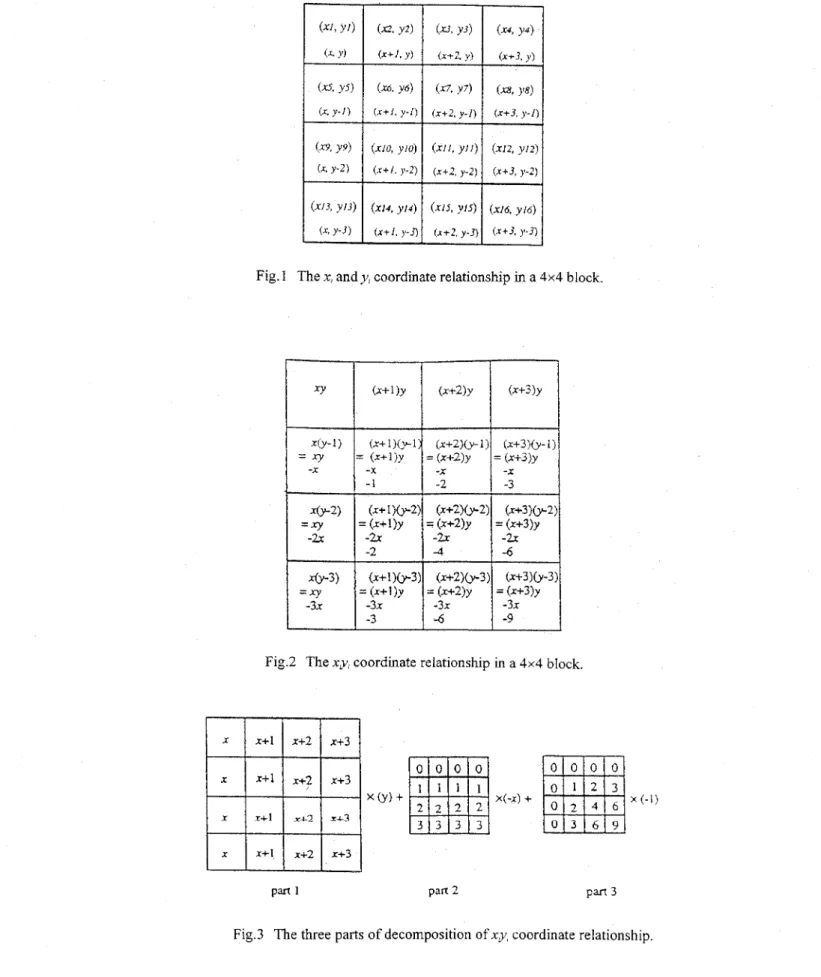
needed. First the relationship of coordinates in a block is taken into consideration. In this discussion the 4x4 block is used as the basic block. A 16x16 block could be composed of sixteen 4x4 blocks. The coordinate relationship of a 4x4 block is shown in Fig. 1. It can be seen that the pixels in a same column get the same X directional coordinate. Also the pixels in a same row get the same Y directional coordinate. So there are only four different X indices and four different Y indices for the 16 coordinates in a 4x4 block. Denoting the left-upper comer coordinate as (x, y), the rest of the element can be denoted as (x+i, y-j) with i, j =
0, 1 , 2 and 3 . By defining
The ith column summation of Ox,@) is
The ith row summation of DxfW is
According to Eqn.(9) there are only 2 multiplications needed to complete the multiplication with xi and y;. To get u3 the multiplication with xg; is needed. In Fig.2 it shows
the relationship of x ~ y , in a 4x4 block. According to this relationship it could be found that the multiplication with XJ+ could be decomposed into three parts of calculation as shown in Fig.3. The calculation of part 1 is first to get signal U ) (complete the multiplication with xi) and then to multiply ul with y . The calculation of part 2 is the computation of
[(Rx2+Rx~)+2(Rx3+Rx4)](-x).
As for the calculation of part 3, according to the relationship of coordinate in Fig. 1, we defineThen the calculation of part 3 is equal to the calculation (01+03)+2(02+03). According to these three parts of calculation there are only two multiplications needed to get u3. The calculations for u5 to ua are similar to the calculations for ul to
UJ. The only different is to replace the input Ox,@)
with D@).
After this, the update term U is used to estimate the new values of motion parameter. Then the next step is to calculate the new corresponding coordinate of pixel. The new coordinate
(x,@),
y,@)) is estimated asAs mentioned in above paragraph, there are only four different X indices and four different Y indices for the 16 coordinates in a 4x4 block. Denoting the left-upper comer coordinates as (x, y), the rest of the element can be denoted as (x+i, y-j) with i,j = 0, 1 , 2 and 3. So to get al@)xi it could use al@h to add with 0, al@), 2xal@) or 3xa1@). To get a2@)y, it could use a,@@ to subtract with 0, a,@), 2xa2@) or 3xa2@). The different in these two calculations is to add or subtract retrievals with different recursive cycle. For calculation of al@)x, the retrieval 0 , al(P), 2xal@) or 3xal@) is changed every cycle and recursively used for every four cycles. For calculation of a2@)yr the retrieval 0 ,
a,@), 2xa2@) or 3xa2@) is changed every four cycles. To get a3@)xy, the relationship between xy, can also be used to reduce the computational amount. The signal x y , in a 4x4 block could be replaced by (x+i)@-j)= wv+vi-xj-ij and so there are only three multiplications of a3@)xy, a3@)x and a3@)y needed
for the estimate a,cPlxy,. In Table.2 it shows the computational amount needed for the calculation of GTD and new corresponding coordinates in a 4x4 block with or without using the coordinate relationship. According to the result in Table.2 it can be seen that the computational amount can be largely reduced according to the relationship of coordinate.
3.1.2 the architecture of block recursive algorithm In above paragraph the reduction of computation amount according to the coordinate relationship is
introduced.
In
this paragraph the corresponding architecture design of the quantized block recursive algorithm is derived. First the architecture for the calculation of GTD is proposed. The architecture is shown in Fig.4 to Fig.5. In Fig.4 the architectures named “ COLUMN” and“ROW’ are to get the column summation and row summation of signals. The architectures named “ SUM-L” and “ SUM-R” are mirrored architecture for the multiplication with x and y . In this figure “FFI” means the flip-flop with clock cycle of onc time unit and “FF4” means the flip- flop with clock cycle of four time units. By combining the architecture of “ COLUMN” and “ROW” with “SUM-L,” and “SUM-R”, the architecture of “ A l ” and “B1”are used to calculate U ] , u2 and u4. In Fig.5 the architecture of “ C l ” is for the calculation of part 3 of ug. Also in this figure number I in the name of module means the clock cycle of one time unit. The architecture “ E l ” is used for the calculations of u ~ , u2, u3 and
u4. In this figure “ ROM x” and “ROM y” are the
memories used to store the X directional coordinatc and Y dircctional coordinatc on the left-upper comer for all 4x4 blocks in a image. The architecture of “C4” is same as “ C l ” but with clock cycle of four time units. Using the same architecture of “ E l ” with input D@J) the update term u5, u6, u7 and
After this, the architecture for the estimate of new motion parameters is composed of adders and registers. This part is very simple and is not discussed here. Then the new corresponding design is shown in Fig.6. In this figure the architecture “ SGl” is to store the value of 0, ay@),
2xa,(P) or 3xal@) in shift register and then shift the data every one clock cycle. In “SG4” the data in shift register is shifted every four clock cycles. In architecture “ D1” the shift register operation is combined with the multiplication with the
could be calculated.
coordinate of pixel is estimated. The architecture
coordinate on left-upper corner to complete the multiplication with x,, y I or xly, and so the new
corresponding coordinate of pixel could be estimated.
3.2 the architecture of block matching algorithm After derived the architecture of the block recursive algorithm, the architecture design for the block matching algorithm is discussed. In the proposed combinative algorithm the block matching method is used after the estimation of the block recursive method has completed. Because the deformed block is used to fmd the best matched block the distribution of pixels of block may be irregular. And so the data access procedure must be arranged with new method. The estimation step for block matching algorithm is described in the following :
Step1 : According the motion parameters estimated by block recursive algorithm, the corresponding coordinate of pixel is calculated. To
calculate the corresponding coordinate architecture “ D l ” derived in Fig6 could be used but with the different clock cycle time.
Step2 : Using the coordinate calculated in step. 1 as center the luminance of pixels in a predefined searching range are downloaded from memory and saved in registers. In our proposed algorithm the searching range is -8 to S. And so in this step the 17x 17 luminance of pixela are downloaded from memory.
Step3 . Estimate all the corresponding DFD of the 17x17 pixel and then add the absolute value of
DFD with the old value of sum of DFD to get the new value of the sum of DFD respectively. After this, the new value of the sum of DFD is stored in register.
Step4 : Repeat step1 to step3 until all the pixels in a 16x16 block have been searched and all the sums of DFD have been calculated. Then Compare all the sums of DFD and find the best matched block and the corresponding motion vector dx and dY.
IV. Conclusion
The combinative motion estimation algorithm is shown to be very effective for the motion parameter estimation with complex motion phenomenon. The improvement is seen to be very significant as compared with the conventional block matching method. In order to reduce the
Liu, Chang and Shen: Combinative Motion Estimation Algorithm and the Corresponding Architecture for Complex Motion Phenomenon
(-1 12,24) (-96,24) (-80,24) 113 18.59 21.48 40.76 0.73 1 19.26 33.46 34.11 1.463 29.50 56.41 66.64 1.310
additional computation amount for the block recursive algorithm the corresponding architecture is proposed. By using the coordinate relationship the computational amount can be largely reduced to meet the requirement of real time estimation. Reference
Arun N. Netravali, Barry G . Haskell, “ Digital Picture Representation and Compression”, AT&T Bell Laboratories, New York, 1988. Georg Musmann, Peter Pirsch, Hans-joachim Grallert, “ Advances in Picture Coding”, Proceedings of IEEE, vo1.73, No.4, April 1985.
M. Hotter, “Differential Estimation of The Global Motion Parameters Zoom and Pan”, Signal Processing, vo1.16, no.3, March 1989, pp.249-265. [41 [51 161 171 181
Y. Nakaya and H. Harashima, “Motion
Compensation Based on Spatial
Transformations”, IEEE Trans. on CAS for Video Technology, vo1.4,no.3, Jun. 1994, pp-
G. A. Clark, S. K. Mitra, S. R. Parker, “Block Implementation of Adaptive Digital Filter”, IEEE Trans. Circuits Syst., vol. CAS-28, June A. Gersho, “Adaptive filtering with Binary Reinforcement”, IEEE Trans. Inform. Theory, vol.IT-30, March. 1984.
W. A. Sethares and Richard Johnsen, “ A Comparison of two Quantized State Adaptive Algorithms”, IEEE Trans. ASSP, vo1.37, No.1, David G. Luenberger, “ Linear and Nonlinear Programming”, Addison- Wesley publishing company, 1984.
339-356.
1981, pp.584-592.
Jan. 1989, pp.138-143.
Table.1 The mean absolute values of DFD of different block with different estimation algorithms and the corresponding zooming motion parameters.
I+
96 addsI+
124 addsI]
Table.2 The comparison
of
computational amount withor
without using the coordinate relationship. (mult : multiplication, add : addition)Fig. 1 The xi and y, coordinate relationship in a 4x4 block. ( x + l ) y (x+2)y (X+3)Y (x+l)*l) (x+2)0.-1) (x+3Ky-l: -1 -2 -3 (x+ 1 j b 2 ) (~+2)+2) (~+3)+2 -27 -2x -2x -2 -4 -6 = ( x + l ) y = (x+2)y = (x+3)y -X -X -X = ( x + l ) y = (x+2)y = (x+3)y
Fig.2 The xy, coordinate relationship in a 4x4 block.
x ( - x ) +
Pm 1 part 2 Pm 3
Liu, Chang and Shen: Combinative Motion Estimation Algorithm
and the Corresponding Architecture for Complex Motion Phenomenon
1
1
1
m
- 1 1
-1Fig.4 The architecture of module “COLUMN”, “ROW’, “SUM-L”, “SUI.,-R”, “A 1” and “B 1” for the
calculation of U,, U, and U,.
c 4
! 1 ! !
U 1 U3 U2 U4
115
! I 4 4
Muil3 3 3 1
Fig.6 The architecture of module “SGl” and “Dl” for the calculation of new corresponding coordinate.