Pacific Graphics 2008
T. Igarashi, N. Max, and F. Sillion (Guest Editors)
Volume 27(2008), Number 7
Capturing Intention-based Full-Frame Video Stabilization
Bing-Yu Chen† Ken-Yi Lee‡ Wei-Ting Huang‡ Jong-Shan Lin§
†‡§National Taiwan University §CyberLink Corp.
Abstract
Annoying shaky motion is one of the significant problems in home videos, since hand shake is an unavoidable effect when capturing by using a hand-held camcorder. Video stabilization is an important technique to solve this problem, but the stabilized videos resulting from some current methods usually have decreased resolution and are still not so stable. In this paper, we propose a robust and practical method of full-frame video stabilization while considering user’s capturing intention to remove not only the high frequency shaky motions but also the low frequency unexpected movements. To guess the user’s capturing intention, we first consider the regions of interest in the video to estimate which regions or objects the user wants to capture, and then use a polyline to estimate a new stable camcorder motion path while avoiding the user’s interested regions or objects being cut out. Then, we fill the dynamic and static missing areas caused by frame alignment from other frames to keep the same resolution and quality as the original video. Furthermore, we smooth the discontinuous regions by using a three-dimensional Poisson-based method. After the above automatic operations, a full-frame stabilized video can be achieved and the important regions and objects can also be preserved.
Categories and Subject Descriptors (according to ACM CCS): I.4.4 [Image Processing and Computer Vision]: Restoration I.4.3 [Image Processing and Computer Vision]: Enhancement
1. Introduction
As the use of digital camcorders grows, to capture videos using hand-held camcorders becomes more and more con-venient than before. However, since most people usually do not bring a tripod with their camcorders, unwanted vi-bration in video is an unavoidable effect due to the hand shakes. To avoid or remove the annoying shaky motion is one of the significant problems in home videos, and video stabilization is an important technique to solve this prob-lem. Many existed video stabilization applications result a stabilized video by smoothing the camcorder motion path and then truncating the missing areas after aligning the video frames along the smoothed camcorder motion path. Hence, the stabilized videos still have many unexpected movements, since only high frequency shaky motions are removed during
† e-mail:[email protected]
‡ e-mail:{kez, weiting}@cmlab.csie.ntu.edu.tw § e-mail:[email protected]
the smoothing stage. Moreover, the quality of the stabilized videos is usually decreased due to the truncation.
In this paper, we propose a robust and practical method of full-frame video stabilization while considering user’s cap-turing intention. To guess the user’s capcap-turing intention, we first consider the regions of interest (ROI) in the original cap-tured video to estimate which regions or objects the user re-ally wants to capture, and then use a polyline to estimate a new stable camcorder motion path while avoiding the user’s interested regions or objects being cut out, since the cam-corder motion path of the video captured with a tripod is like a polyline. Hence, the resulted video is much stable and much close to the video that the user wants to capture, since the capturing regions and objects are preserved and the cam-corder motion path is stabilized as capturing with a tripod. To align the video frames along the stabilized camcorder motion path causes some missing areas, which need to be completed. While estimating the camcorder motion path, we also take the possibility of missing area completion into con-sideration.
c
2008 The Author(s)
Completion Completion
Possion-based Smoothing
Output
sta bilized video sequence
Video Deblurring
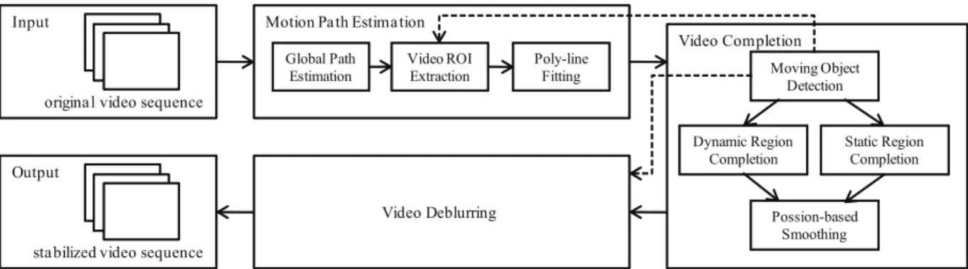
Figure 1: System framework.
After aligning the video frames, we fill the dynamic and static missing areas respectively. Since we use a polyline to fit the camcorder motion path rather than using a paramet-ric curve, the missing areas are usually large and can not be easily completed by neighboring frames. To fill the missing areas using the frames far from the current one may cause discontinuity at the boundary of the filled areas, since the intensity of each video frame is usually not necessarily the same. Hence, we smooth the discontinuous boundaries by using a three-dimensional Poisson-based method while tak-ing both of the spatial and temporal consistency into consid-eration, so that it can result seamless stitching spatially and temporally.
2. Related Work
Video stabilization is an important research topic in mul-timedia, image processing, computer vision, and computer graphics. Buehler et al. proposed an image-based render-ing (IBR) method to stabilize videos [BBM01]. For esti-mating the camcorder motion path, Litvin et al. estimated a new camcorder motion path by altering the camera parame-ters [LKK03], and Matsushita et al. smoothed the camcorder motion path to reduce the high frequency shaky motions [MOTS05]. However, although the high frequency shaky motions can be easily reduced, the stabilized videos still have low frequency unexpected movements. Gleicher and Liu stabilized the camcorder motion to be piecewise con-stant [GL07], which is similar with our method, but we also take the ROI and the possibility of missing area completion into consideration.
When filling up the missing image areas, there are some image inpainting approaches developed for recovering the missing holes in an image [BSCB00,CPT03,LZW03]. Al-though these approaches can complete the missing regions with correct structure, but there will be obvious temporal discontinuity if we recover each video frame individually. Litvin et al. used a mosaic method to fill up the missing areas in the stabilized video [LKK03], however they did not consider the moving objects may appear at the
bound-ary of the video frames. Wexler et al. and Shiratori et al. filled up the missing holes by sampling the spatio-temporal volume patches from other portions of the video volume [WSI04,SMTK06]. The former approach used the most sim-ilar patch in color space for completing the missing areas and the later one used the patch with similar motion vector. The drawback of these methods is that they need large comput-ing time for searchcomput-ing a proper patch. Matsushita et al. also provided motion inpainting to complete the moving objects appeared at the boundary of the video frames [MOTS05]. Jia et al. and Patwardhan et al. segmented the video into two layers and recovered them individually [JWTT04,PSB07]. These methods focused on long and periodic observed time of the moving objects, but this is not guaranteed in common home videos.
3. Overview
Figure1shows the system framework of our algorithm. The input of our system is a video captured by a hand-held cam-corder without using a tripod. Hence, the video has much annoying shaky motions due to the hand shakes. The first process of our system is motion path estimation (Section 4). In this process, the camcorder motion path of the orig-inal video is estimated and changed to be a stabilized one. There are three steps contained in this process. In the first step (Section4.1), we find out the transformation between the consecutive frames and combine all of the transforma-tions to obtain the global camcorder motion path of the orig-inal video. In the second step (Section4.2), we extract the video ROI from the video by considering both of the spatial and temporal regions of interests. In the third step (Section 4.3), the estimated global camcorder motion path is approx-imated by a polyline. When the estapprox-imated camcorder motion path is fitted by a polyline, the extracted video ROI and the possibility of missing area completion are also taken into consideration in order to avoid the user’s interested regions or objects being cut out and make the stabilized camcorder motion path as stable as possible.
B.-Y. Chen, K.-Y. Lee, W.-T. Huang, & J.-S. Lin / Capturing Intention-based Full-Frame Video Stabilization
Figure 2: Top row: Three frames of the original video.
There are annoying shaky motions in the video. Middle row: Aligned frames, where the black regions show the missing areas. Bottom row: Completed frames, which are the result of our method; the shaky motions is stabilized.
the video completion process is applied (Section5). Be-cause the position of each frame is changed according to the frame alignment along the new camcorder motion path, there are some missing areas within each aligned frame. The first step is to detect if there exists moving objects and where they are (Section5.1). In the second step, we separate the moving objects as the dynamic foreground regions from the static background regions and complete the missing areas of them by different methods (Sections5.2and5.3). To fill the missing areas using the frames far from the current one may cause discontinuity at the boundary of the filled areas, since the intensity of each video frame is usually not nec-essarily the same. In order to make a seamless stitching, we apply a three-dimensional Poisson-based smoothing method to smooth the discontinuous regions (Section5.4).
The last process is video deblurring (Section6). Because the motion blur of each frame may not be matched in the stabilized camcorder motion path, the blurry frames become much noticeable in the stabilized video. Instead of finding the accurate point spread function (PSF) for image deblur-ring, we use a video deblurring method by transferring the pixels from neighboring sharper frames to the blurry ones. After the above automatic processes, the output ia a stabi-lized video with a stable camcorder motion path while keep-ing the same resolution and quality as the original one. Fig-ure2shows three frames of an input video and its stabilized result before and after the video completion process.
4. Motion Path Estimation 4.1. Global Path Estimation
To estimate the global camcorder motion path, we first ex-tract the feature points of each frame by SIFT (Scale
Invari-Figure 3: The detected moving objects.
ant Feature Transform) [Low99], which is invariant to scal-ing and rotation of the image. The feature points on every consecutive frames are matched if the distances between the feature descriptions are small enough and RANSAC (RAN-dom SAmple Consensus) [FB81] is used to select the inliers of the matched feature pairs. Then, an over-constrained sys-tem is applied to find out the least square solution between these matched feature pairs and derive the affine transfor-mation between the two consecutive frames. If the affine transformation matrix Tibetween frames i and i + 1 is
con-structed, the pixel pion frame i and its corresponding pixel
pi+1 on frame i + 1 will have the following relationship: pi+1= Ti· pi. Once the transformation matrices between the
consecutive frames are obtained, all of the transformations can be combined to derive a global transformation chain.
4.2. Video ROI Extraction
To extract the video ROI from the input video, we take the temporal and spatial attention models into consideration to produce the spatio-temporal saliency maps. The spatial at-tention model is based on an image ROI extraction method proposed by Itti et al. [IKN98], and the temporal attention model is extracted by considering the moving objects in the video, which is detected by using the local motion vectors obtained in Section5.1.
In order to detect the moving objects in current frame i with whatever small or large motion, we detect the moving objects by checking the local motion vectors from the previ-ous n frames to the next n ones, where n is a frame window size. After detecting the moving objects in the 2n+1 frames, the frame window size n is set to be 2n to detect the moving objects again in order to detect large motion. To generate the temporal saliency map SalT (i) of frame i, we combine the temporal saliency maps SalT (i)nin different frame window
sizes n by taking the union of the temporal saliency maps. Figure3shows the detected result.
To obtain the spatio-temporal attention model by combin-ing the temporal and spatial attention models, we have to set the fusion methodology first. According to some obser-vations, if the motion of the moving objects is large in the video, the spatio-temporal attention model should incorpo-rate the temporal attention model more, otherwise it should incorporate the temporal attention model less. Then, the
0 50 100 150 200 250 300 350 400 450 500 −50 frame 0 50 100 150 200 250 300 350 400 450 500 −40 frame
Figure 4: The original camcorder motion path (red curve)
and the estimated ones after applying the Kalman filter (green curve) and fitting by a polyline (blue straight line) for horizontal (Left) and vertical (Right) directions.
spatio-temporal saliency map Sal(i) is defined as Sal(i) =
kti× SalT (i) + ksi× SalS(i) [ZS06], where SalT (i) and
SalS(i) are the temporal and spatial saliency maps of frame
i, and the weighting parameters ktiand ksiare defined as
kti= αi αi+ β , ksi= β αi+ β , (1)
where β ∈ (0, 1) is a constant value and αi=
SalT(i)
max(SalT (i)) − min(SalT (i)). (2)
4.3. Motion Path Fitting
To obtain a stabilized camcorder motion path without not only the high frequency shaky motions but also the low frequency unexpected movements, we use a polyline to fit the estimated global camcorder motion path, since the cam-corder motion path of the video captured with a tripod is like a polyline. We first separate the camcorder motion path es-timated from Section4.1to be horizontal and vertical ones, and operate them respectively. Then, Kalman filter is em-ployed to estimate a smooth camcorder motion path [PN04] while considering the video ROI extracted from Section4.2. The camcorder motion path smoothed by the Kalman filter (Kalman path) is shown as the green curves in Figure4.
Then, we use a polyline to fit the Kalman path while con-sidering the possibility of missing area completion. To fill the missing areas, ideally it can be done by copying pixels from other frames. Once it cannot be simply achieved, we will use image inpainting to fill the monotonous missing ar-eas to make the stabilized camcorder motion path as stable as possible. Hence, the possibility of missing area completion is evaluated by using the gradient of each frame’s boundary areas. Then, the camcorder motion path is fitted by a poly-line while taking the video ROI and the possibility of miss-ing area completion into consideration as shown as the blue polyline in Figure4.
Once the camcorder motion path is fitted by a polyline, the video frames are aligned along the polyline-fitted camcorder motion path. If the global transition matrix from the first
Figure 5: Top row: Aligned frames of the top row of Figure
2without considering video ROI. The black regions show the missing areas and the building is cut out. Bottom row: The saliency maps of the top row of Figure2.
frame to the i-th frame is denoted by Mi, then the i-th frame
is aligned to Mi· ∏0j=i−1T−1j · pi, where pimeans the pixels
on the i-th frame and Tjrepresented the affine
transforma-tion matrix between j-th frame and j + 1-th frame. Hence, we can obtain a stabilized video after the polyline fitting and frame alignment. The top row of Figure5shows the frames aligned by a polyline-fitted camcorder motion path without taking video ROI into consideration. Hence, the building in the original video which the user wants to capture is cut out. By considering the saliency maps of the original video as shown in the bottom row of Figure5, we can find a proper polyline-based camcorder motion path and the stabilized re-sult is shown in the bottom row of Figure2.
5. Video Completion
After aligning the video frames along the stabilized cam-corder motion path, there are several missing areas in the stabilized video. To complete the video, we first detect the moving objects to segment the video to a static background region and some dynamic moving object regions (Section 5.1). Then, we complete the missing areas by filling dynamic regions (Section5.2) and static regions (Section5.3) respec-tively.
5.1. Moving Object Detection
In order to detect the moving objects, we first align every pair of adjacent frames by using the affine transformation obtained in Section4.1. Then, we evaluate the optical flow of them [BA96] to obtain the motion vector of each pixel. The motion vector of pixel pi can be described as Fi(pi)
which represents the motion flow at pixel pifrom frame i to
i+ 1, and the length of the motion vector shows the motion value. Hence, the pixel pion frame i and its corresponding
pixel pi+1on frame i+1 according to the motion vector have
the relationship: pi+1= Ti· Fi(pi), since the motion vector
is obtained after aligning the frame according to the affine transformation matrix Ti.
B.-Y. Chen, K.-Y. Lee, W.-T. Huang, & J.-S. Lin / Capturing Intention-based Full-Frame Video Stabilization
Figure 6: Left: The frame after aligning to the stabilized
camcorder motion path. Right: The mask of detected moving objects (white regions).
fra me i+1
fra me i missinga rea
1 i q 2 i q 3 i q pi 1 1 i p+ 1 1 i q+ 2 1 i q+ 3 1 i q+ 2,3 1 i p+
Figure 7: The motion vector of pixel piat the missing area
of frame i is determined by weighted averaging the motion vectors of its neighboring pixels qij, j= 1, 2, 3 at the known
area. The weight is defined by the color difference between piand qij. Hence, even if the directions of the motion vectors
of the neighboring pixels are not the same (like q1i+1), ac-cording to the color similarity of pi+1and qij+1, the motion vector to p2,3i+1will be used and that to p1i+1will be almost ignored.
The motion values in the moving object regions are con-sidered to be relatively larger than those in the static back-ground regions. Hence, we can get a simple mask to show the regions with large motion values by a simple threshold as shown in Figure6. The dynamic regions are obtained by evaluating the dilation of the mask, which can help to guar-antee the boundary of the moving objects are involved in the dynamic regions. If the missing area falls in the region where the neighboring pixels have been masked as the dy-namic one, this area is treated as the dydy-namic region and motion inpainting (Section5.2) is used to complete the area, otherwise we recover the area by mosaicing (Section5.3).
5.2. Dynamic Region Completion
For the dynamic missing regions, instead of filling the color values from other frames directly, we want to fill them with correct motion vectors. Once we derive the motion vectors of each pixel in the missing areas, we can get the pixel color from the next frame according to the motion vectors. The lo-cal motion vectors in the known areas obtained in Section5.1 are propagated to the dynamic missing areas as [MOTS05].
First, the local motion vectors are estimated by computing
Figure 8: Upper-Left: The frame after aligning to the
sta-bilized camcorder motion path. There is a missing area at the left side and a moving object across the missing area. Lower-Left: The result of dynamic region completion. Right Column: The close-up view of the yellow rectangles in the Left Column.
the optical flow between the stabilized video frames [BA96]. The propagation starts at the pixel on the boundary of the dy-namic missing areas, its local motion vector is calculated as a weighted average of the motion vectors of its neighboring pixels at known areas. The process will continue until the dynamic missing areas are filled with motion vectors com-pletely. If piis a pixel in the missing area, it will be filled
according to its motion vector which is determined by
Fi(pi) =
∑qi∈Npiw(pi, qi)Fi(qi) ∑qi∈Npiw(pi, qi)
, (3)
where w(pi, qi) determines the contribution of the motion
vector Fi(qi) of pixel qi, and Npi denotes the neighboring pixels of pi. Suppose the neighboring pixel qi∈ Npialready has a motion vector, according to its motion vector, we can estimate its position on the next frame as qi+1. By using the
geometric relationship between the pixels piand qi, the
po-sition of pixel pi+1can also be determined as illustrated in
Figure7. Since the pixels in the same object have similar color values and move in the same direction, if the differ-ence between the color values of the pixels pi+1 and qi+1
is small, they will likely belong to the same object, and the weight of the motion vector of pixel qiis set to be large as
w(pi, qi) = 1/(ClrD(pi+1, qi+1) + ε), (4)
where ε is a small value for avoiding the division by zero and ClrD(pi+1, qi+1) is the l2-norm color difference in RGB
color space of the pixels pi+1 and qi+1. This weight term
guarantees that the contribution of the motion vector in dif-ferent objects is small. Figure8shows the result.
Figure 9: Left: The frame after changing the position
ac-cording to the stabilized camcorder motion path. There is a missing area at the right side and upper side. Right: The result of static region completion. Since the missing area is large, there is a discontinuity boundary between the recov-ered pixels and the original frame.
5.3. Static Region Completion
After completing the dynamic regions, we then recover the static ones by its neighboring frames which are wrapped ac-cording to the affine transformation obtained in Section4.1. For the pixel piin the static missing area at frame i, if there
exists its corresponding pixel pi0 at the warped neighboring
frame i0, we directly copy the pixel p
i0 to the missing pixel
pi. Figure9shows the static region completion result.
To find the corresponding pixel pi0 of pi, we begin the
search from the nearest neighboring frame and propagate the search out. For example, if i is the current frame we want to recover, we search the frames i − 1 and i + 1 first, if there are missing areas still have not been recovered by the two frames, the following two frames i − 2 and i + 2 are used to recover the missing areas. We keep the search until all missing pixels in the static missing areas are completed or all frames are searched. Finally, if there are still some missing areas, we then use image inpainting to complete them. Since the polyline-fitted camcorder motion path is determined by considering the gradient of each frame’s boundary areas, the rest missing areas can always be completed.
5.4. Poisson-based Smoothing
Although the missing areas caused by the stabilized cam-corder motion path are completed, there may be a discontin-uous boundary between the recovered pixels and the origi-nal frame, since the missing areas may be large and needed to be filled from the frame far from the current one. In or-der to keep the spatial and temporal continuity, we provide a three-dimensional Poisson-based smoothing method, which is extended from [PGB03].
To solve the discontinuity problem, before filling in a pixel from other frames, the Poisson equation is applied to obtain a smoothed pixel by considering its neighboring pix-els in the same frame and neighboring ones. We first apply the Poisson equation in the spatial domain which is written
Figure 10: Upper-Left: The frame after video completion.
Since the missing area is large, there is a discontinuous boundary between the recovered pixels and the original frame. Lower-Left: The result of video completion with Poisson-based smoothing. Right Column: The close-up view of the yellow rectangles in the Left Column.
as: For all p ∈ Ω, |Np| fp−
∑
q∈Np∩Ω fq=∑
q∈Np∩∂Ω fq∗+∑
q∈Np vpq, (5)where Ω denotes the missing area, p is a pixel in the missing area Ω, Npdenotes the neighboring pixels of pixel p, |Np|
is the number of neighboring pixels Np, fpand fqare the
correct pixel values of pixels p and q which are what we want to derive, vpq determines the divergence of pixels p
and q, ∂Ω is the region surrounding the missing area Ω in the known areas, and f∗
q denotes the known color value of
pixel q in ∂Ω.
The Poisson equation can keep the correct structure in the missing area and achieve a seamless stitching between the recovering areas and the known ones. In order to achieve temporal coherence, after recovering the missing areas of each frame, we correct the pixel values of the missing areas by apply the Poisson equation again by considering not only the spatial neighboring pixels but also the temporal neigh-boring ones. Hence, the Poisson equation is the same as Eq. (5), but Npincludes all neighboring pixels of pixel p in the
video volume. Figure10shows the result.
6. Video Deblurring
After video stabilization, the blurry frames which look smooth in the original video become noticeable. Our video deblurring method fundamentally based on [MOTS05], but we separate the moving objects from static background first and deal with them separatively as the video completion pro-cess. The main idea of this method is to copy the pixels from neighboring sharper frames to the blurry ones. We first eval-uate the "relative blurriness" of each frame by calculating
B.-Y. Chen, K.-Y. Lee, W.-T. Huang, & J.-S. Lin / Capturing Intention-based Full-Frame Video Stabilization
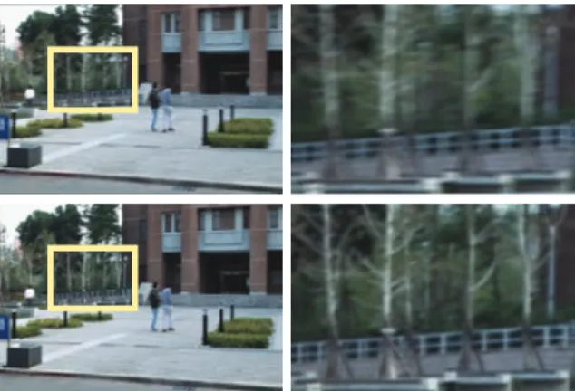
Figure 11: Upper-Left: A blurry frame. Lower-Left: The
re-sult of video deblurring. Right Column: The close-up view of the yellow rectangles in the Left Column.
the gradient of it. Generally, the gradient of blurry image is smaller than that of sharper one at the same regions. With this assumption, the blurriness of frame i is defined as:
Bi=
∑
pi(gx(pi)2+ gy(pi)2), (6)
where piis the pixel on frame i, and gxand gyare the
gradi-ents of x− and y− directions, respectively. We can derive the relative blurriness between the current frame and its neigh-boring ones by comparing their blurriness Bi. If the
blurri-ness Biof current frame i is smaller than the blurriness Bi0
of its neighboring frames i0, then the frames i0are treated to
be sharper than the frame i, and we can use the frames i0to
recover the current blurry frame i by transferring the corre-sponding pixels from the frames i0to i by
˜pi=
pi+ ∑i0∈Niwii0pi0
1 + ∑i0∈Niwii0
, (7)
where ˜piand piare the same pixel on frame i after and before
the deblurring operation, Nidenotes the neighboring frames
of current frame i, pi0 is the corresponding pixel of pi
ac-cording to affine transformation Ti
i0and local motion vector
Fii0(pi0) from frame i0∈ Nito i, i.e., pi= Tii0pi0 for static
regions and pi= Tii0Fii0(p0i) for dynamic ones, and wii0 is a
weighting factor between i0and i which is defined as: wii0=
(
0 if Bi0/Bi< 1
Bi0/Bi otherwise
. (8)
Figure11shows the result.
7. Result
All of the videos used in this paper was captured by using a hand-held camcorder without using a tripod, and the res-olution of the videos are 720 × 480. The resres-olution of all resulted (stabilized) videos are the same as the input ones.
Figure2and Figures12∼15show our results. In Figure2, the user wants to use the hand-held camcorder to capture a panorama view. Without a tripod, the captured video are shaky due to the hand shakes. Although the camcorder mo-tion path can be stabilized by a polyline-based camcorder motion path, without taking video ROI into consideration, the stabilized motion path may cause the building to be cut out as the top row of Figure5. The bottom row of Figure2 shows our result which is stabilized as captured by using a tripod and the building could be preserved in the stabilized video.
In Figure12, the user wants to use the hand-held corder to capture a static scene. Although the shaky cam-corder motion path can be smoothed by using other smooth-ness methods, the second row of Figure12 still has some unwanted motions. The bottom row of Figure12shows our result. The estimated camcorder position is fixed as captured by using a tripod. For comparison, the forth row of Figure 12shows the result of truncating the missing areas and the resolution is reduced.
In Figure13, the user wants to use a hand-held camcorder to capture a man walking with his child. Without a tripod, the captured video are shaky due to the hand shakes. The bottom row of Figure13shows our result which is stabilized as captured by using a tripod. In Figure14, the user wants to use a hand-held camcorder to capture a man playing with his dog, but due to the view angle limitation, the user pans the camcorder a little bit to capture the whole scene. The bottom row of Figure14shows our result and the stabilized camcorder motion path is just like to capture the scene by using a tripod. In Figure15, the user wants to use a hand-held camcorder to capture some high buildings. The right column of Figure15shows out result, and the blurry frame specified by the orange rectangle has also been deblurred.
8. Conclusion and Future Work
A full-frame video stabilization approach is proposed in this paper to obtain a stabilized video while considering the video ROI in the input video. Since we use a poly-line to fit the original camcorder motion path, the stabi-lized camcorder motion path is much more stable than other smoothness approaches. Hence, in the stabilized video, not only the high frequency shaky motions but also the low fre-quency unexpected movements are removed. Although us-ing a polyline to estimate the camcorder motion path may cause large missing areas and may cut out some capturing objects, the two problems are solved by applying a three-dimensional Poisson-based smoothing method and taking the video ROI into consideration. To fill the missing areas from other frames and deal with blurry frames, we separate the moving objects from the static background and deal with them respectively in completion and deblurring processes.
Our limitation is that, if the moving objects occupy too
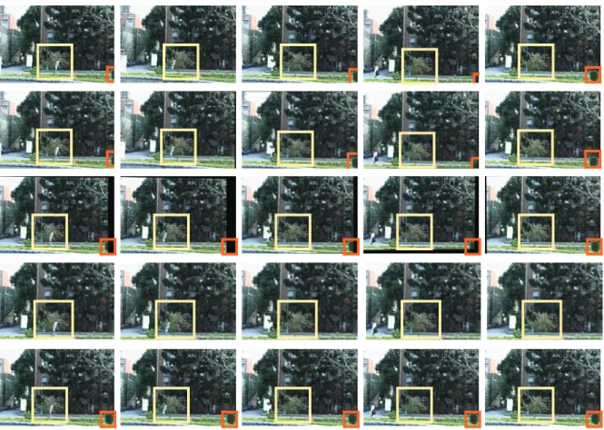
Figure 12: Top row: Five frames of the original video. Orange and yellow rectangles show two trees in the video. Due to the
camcorder hand-shake, the locations of the rectangles in each frame are different. Second row: Stabilized frames resulted by smoothing the camcorder motion path. The black regions show the missing areas. Since only high frequency shaky motions are removed, the rectangles still locate at different place in each frame. Third row: Stabilized frames resulted by polyline-fitted camcorder motion path. The locations of the trees (rectangles) are almost the same, but the missing areas are large. Fourth row: The result produced by truncating the missing areas of the third row. The resolution of the stabilized video is reduced, and the tree specified by the yellow rectangle has been cut out. Bottom row: Our result.
large area in the video frames, there will be some problems about finding the affine transformation matrix. The inaccu-racy transformation matrix would cause the result faulty. To deal with large moving objects is one of our future work. In addition, some problems about filling up missing areas and catching camcorder motion path will appear if the user shakes the camera calculatedly to cause the video juddering. Although the blurry frames are deblurred, our video deblur-ring method still can not deal with extreme blurry frames.
Acknowledgments
We would like to thank anonymous reviewers for their valu-able comments. This work was partially supported by the National Science Council of Taiwan under
NSC95-2622-E-002-018 and NSC96-2622-E-002-002, and also by the Ex-cellent Research Projects of the National Taiwan University under NTU95R0062-AE00-02.
References
[BA96] BLACK M. J., ANANDAN P.: The robust
esti-mation of multiple motions: parametric and piecewise-smooth flow fields. Computer Vision and Image
Under-standing 63, 1 (1996), 75–104.
[BBM01] BUEHLER C., BOSSE M., MCMILLAN L.:
Non-metric image-based rendering for video stabiliza-tion. In IEEE Computer Vision and Pattern Recognition
2001 Conference Proceedings (2001), vol. 2, pp. 609– 614.
B.-Y. Chen, K.-Y. Lee, W.-T. Huang, & J.-S. Lin / Capturing Intention-based Full-Frame Video Stabilization
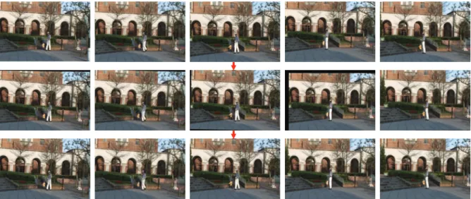
Figure 13: Top row: Five frames of the original video. Middle row: Stabilized frames. The black regions show the missing areas.
Bottom row: Our result.
Figure 14: Top row: Five frames of the original video. Middle row: Stabilized frames. The black regions show the missing areas.
Bottom row: Our result.
[BSCB00] BERTALMIOM., SAPIROG., CASELLESV.,
BALLESTERC.: Image inpainting. In ACM SIGGRAPH
2000 Conference Proceedings(2000), pp. 417–424.
[CPT03] CRIMINISIA., PEREZP., TOYAMAK.: Object
removal by exemplar-based inpainting. In IEEE
Com-puter Vision and Pattern Recognition 2003 Conference Proceedings(2003), vol. 2, pp. 721–728.
[FB81] FISCHLERM. A., BOLLESR. C.: Random
sam-ple consensus: a paradigm for model fitting with applica-tions to image analysis and automated cartography.
Com-munications of the ACM 24, 6 (1981), 381–395.
[GL07] GLEICHER M. L., LIUF.: Re-cinematography:
improving the camera dynamics of casual video. In ACM
Multimedia 2007 Conference Proceedings(2007), pp. 27– 36.
[IKN98] ITTI L., KOCH C., NIEBUR E.: A model of
saliency-based visual attention for rapid scene analysis.
IEEE Transactions on Pattern Analysis and Machine In-telligence 20, 11 (1998), 1254–1259.
[JWTT04] JIA J., WU T.-P., TAI Y.-W., TANG
C.-K.: Video repairing inference of foreground and back-ground under severe occlusion. In IEEE Computer
Vi-sion and Pattern Recognition 2004 Conference Proceed-1813
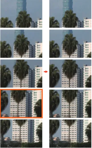
Figure 15: Left: Five frames of the original video. Right:
Our result. The blurry frame specified by the orange rectan-gle has been deblurred.
ings(2004), vol. 1, pp. 364–371.
[LKK03] LITVINA., KONRADJ., KARLW. C.:
Proba-bilistic video stabilization using Kalman filtering and mo-saicking. In Proceedings of 2003 SPIE Conference on
Electronic Imaging(2003), vol. 5022, pp. 663–674.
[Low99] LOWE D. G.: Object recognition from local
scale-invariant features. In Proceedings of 1999 IEEE
International Conference on Computer Vision (1999),
pp. 1150–1157.
[LZW03] LEVIN A., ZOMET A., WEISS Y.: Learning
how to inpaint from global image statistics. In
Proceed-ings of 2003 IEEE International Conference on Computer Vision(2003), vol. 1, pp. 305–312.
[MOTS05] MATSUSHITAY., OFEKE., TANGX., SHUM
H.-Y.: Full-frame video stabilization. In IEEE
Com-puter Vision and Pattern Recognition 2005 Conference Proceedings(2005), vol. 1, pp. 50–57.
ceedings(2004), pp. 69–76.
[PSB07] PATWARDHANK. A., SAPIROG., BERTALMIO
M.: Video inpainting under constrained camera motion.
IEEE Transactions On Image Processing 16, 2 (2007),
545–553.
[SMTK06] SHIRATORI T., MATSUSHITA Y., TANGX.,
KANGS. B.: Video completion by motion field transfer. In IEEE Computer Vision and Pattern Recognition 2006
Conference Proceedings(2006), vol. 1, pp. 411–418.
[WSI04] WEXLER Y., SHECHTMAN E., IRANI M.:
Space-time video completion. In IEEE Computer Vision
and Pattern Recognition 2004 Conference Proceedings
(2004), vol. 1, pp. 120–127.
[ZS06] ZHAIY., SHAHM.: Visual attention detection in
video sequences using spatiotemporal cues. In ACM
Mul-timedia 2006 Conference Proceedings(2006), pp. 815–