行政院國家科學委員會專題研究計畫 期中進度報告
精密拋光研究--從極微觀角度看拋光行為(1/2)
計畫類別: 個別型計畫 計畫編號: NSC94-2212-E-110-017- 執行期間: 94 年 08 月 01 日至 95 年 07 月 31 日 執行單位: 國立中山大學機械與機電工程學系(所) 計畫主持人: 蘇耀藤 計畫參與人員: 章少衡,沈孟輝,黃立漢,劉飛飛,謝志豪 報告類型: 精簡報告 處理方式: 本計畫可公開查詢中 華 民 國 95 年 5 月 30 日
行政院國家科學委員會補助專題研究計畫
□ 成 果 報 告
■期中進度報告
精密拋光研究-從及微觀角度看拋光行為(1/2)
計畫類別:▓ 個別型計畫 □ 整合型計畫
計畫編號:NSC94-2212-E-110-017
執行期間: 94 年 8 月 1 日至 95 年 7 月 1 日
計畫主持人:蘇耀藤
共同主持人:
計畫參與人員:章少衡,沈孟輝,黃立漢,劉飛飛,謝志豪
成果報告類型(依經費核定清單規定繳交):▓精簡報告 □完整報告
本成果報告包括以下應繳交之附件:
□赴國外出差或研習心得報告一份
□赴大陸地區出差或研習心得報告一份
□出席國際學術會議心得報告及發表之論文各一份
□國際合作研究計畫國外研究報告書一份
處理方式:除產學合作研究計畫、提升產業技術及人才培育研究計畫、
列管計畫及下列情形者外,得立即公開查詢
□涉及專利或其他智慧財產權,□一年□二年後可公開查詢
執行單位:
中 華 民 國 95 年 5 月 30 日
中文摘要 本研究利用分子動力學來探討在拋光過程中磨粒在工件表面上滾動或滑動對工件表面 的加工行為所造成的影響。對於除了運動方式的改變外,另外還有探討下壓深度、磨粒的 形狀以及磨粒與工件之間的吸附強度的改變,對於磨粒運動過後的移除量、變質層的數目 以及磨粒運動過後所衍生的粗度的所產生的影響。 由模擬中發現,磨粒以滾動運動會比滑動運動來的容易對工件表面的原子造成移除。 就滾動運動而言,對工件表面原子會造成移除量的關鍵是磨粒與工件之間的吸附強度必須 夠大。就滑動而言,吸附強度不是影響移除量的為一因素,在滑動過程中欲造成原子的移 除,除了吸附強度夠大之外,其磨粒與工件之接觸角也必須夠小才行。 工件表面下的變質層原子在圓球狀磨粒作用下,不管滾動或滑動與吸附強度成正比, 而在不同形狀的滑動過程中則需額外考慮接觸角的影響。而磨粒衍生的粗糙度,滾動過程 中吸附強度較小穢語吸附強度有關,其他狀況下其趨勢趨於不明顯。 英文摘要
This paper studied the surface phenomena induced by a particle traversing on the work via the molecular dynamics simulation method. The effect of adhesion between particle and work on the phenomena was especially noted. The particle, at a predefined depth, traversed on the work in either pure sliding or rolling motion. The material removal rate, induced surface roughness, depth of the damaged layer and other phenomena were observed and analyzed to examine how they were affected by adhesion and the motion of the particle. The results showed that the adhesion had significant effect on the induced phenomena when the particle rolled on the work. It was not the case for sliding particle. A mechanism was proposed to explain the distinct phenomena due to different particle motions.
前言、研究目的
The phenomena induced by a particle, which traversed on a smooth surface, were studied. The adhesion between the particle and work was especially noted. The particle was in size of several tenths of nanometer. It was composed by carbon with the diamond structure. The particle was indented into work with the depth of several nanometers. After the depth reached, the particle pure rolled or slid on the work surface. The work was composed by the silicon in diamond structure also. After the particle moved on the smooth surface, the work atoms had relative motions. These motions were called induced phenomena in this paper. They were categorized as material removal, induced surface roughness and damaged layer. The effects of adhesion on these phenomena were studied to investigate the possibility of achieve high quality
surface by polishing process.
Usually, the industry obtains the high quality surface by polishing process. The high quality is pointed to very smooth surface and very thin damaged layer. The polishing process lowered the surface roughness and thinner the damaged layer by removing work material gently. The process was done by abrasives slurry. During the process, the abrasives were against work surface by the tool’s or slurry’s interaction. Because the force between particle and work was little, the material could be removed without increasing the damaged layer too much. One feature of polishing is that the material removal rate is sensitive to the surface irregularity. The rate was high on the convex locations and low on the concave locations of surface irregularity. Finally, the differences in altitude were decreased and the roughness lowered. All the above phenomena were due to interaction between particle and surface. In micro view of the
interaction area, the real contact area was very small. The interaction area might include several hundreds of atoms. To understand how to get a high polishing process, the phenomena should be studied in atomic scale.
It was important to consider the adhesion when the polishing process was studied in atomic scale. The effect adhesion between surfaces would become significant in the atomic scale. Indeed, the adhesion had been applied to study various phenomena of polishing, such material removal and tool wear. Other studies also stated the interaction between particle and work was the main cause of polishing process. The material removal was the results of relative motions among atoms. Because adhesion effected the material removal, the adhesion affected the motions of atoms. The moving atoms meant the atom left the original latticed position. thus, the amorphous structure might occurred as to damaged layer induced. On the other hand, the smooth surface might be disturbed due to atoms motions. Hence, the surface roughness might be induced. Moreover, this roughness might be not removed. These let us consider the limitation of the polishing process on high quality surface.
Limit information was offered about the damaged layer and induced surface roughness. Mori claimed the polished surface could be ultra smooth with no damaged layer by implementing EEM. The EEM addressed the bonding force (or adhesion) between abrasive and work was the key. As stated before, the surface should contain damaged layer, even it might be atomic scale. Its validation of damaged-free result was worth suspect in atomic scale. As to roughness, the phenomenon of ultimate surface roughness was found. Su et al proposed an experimental model to predict the value of the ultimate surface roughness. Due to limit number of experiments, the results might be difficult to expand to all polishing process.
Little was the study that considered the effect of adhesion on phenomena in atomic scale. The topics of studies mainly focused on nano-indentation, traditional cutting as well as tiny particle motion on work surface [1-12]. Cheong used a diamond probe to indent silicon work piece [3]. The silicon generated phase transformation and resulted in a plastic deformation. Fang conducted cutting simulation [9]. The results showed the friction forces between work and tool had no relation with the tool speed. Other studies showed the adhesive strength between particle or tool between works affected the friction force [5,10].
The current study adopted the molecular dynamics simulation method to study the problem. The method had two significant advantages. First one was the interaction forces among atoms were explicit. Thus, the adhesion or bonding effect could be easily evaluated. The second one was the behaviors of all atoms were observed. Hence, one could understand how and why the phenomena happened. In the following, the simulation issues and condition were stated. The material removal rate induced surface roughness and damaged layer was converted from raw data of simulation. Finally, the proposed mechanism described the effect of adhesion.
研究方法
The accuracy and efficiency of the computation are the important issues in this molecular dynamic simulation study. It was also necessary to conveniently express and analyze the simulations results, the various induced phenomena. Besides, the study needed to notice the effect of the adhesion between particle and work. Thus, in this section, the adhesive strength index was introduced to represent the adhesion. Then, the factors affected the accuracy and efficiency were briefly explained. Several techniques were proposed to seek balance between the accuracy and efficiency. Finally, indexes were introduced to express the simulations results.
The adhesive strength index was introduced to represent the adhesion between particle and the work. The total adhesion was the sum of force between individual pair of two atoms, where one is the particle atom and the other was the work atom. The force between two atoms was derived from the potential of that atom. In MD, the potential was calculated from potential function. Due to correct estimation of force guarantee correct behaviors between atoms. The proper adoption of potential function was necessary. In this study, the Tersoff’s potential function was used. This potential was suitable for carbon and silicon. Besides this, to study the effect of the adhesion between particle and work, the adhesion had to be convenient to change to any level. In this paper, we changed the potential function to modify the adhesion between particle and work surface. The adhesion strength index was used to change the potential function in this study. The adhesive strength index was a constant value multiplied in the front of the potential function which belong to particle-work atoms pair. The absolute value of the potential can be enlarged or lessened by the value of the index. Hence, the interaction force, derivative of the potential change, between particle-work atom pair changed. Finally, the adhesion between particle and work adjusted. It was such that the level could be any desired value. It would be helpful to plan the simulation.
The accuracy of MD simulations was based on sufficient large number of atoms. The goal of this study was to research the induced phenomena at the scale of atomic size. By using MD methods, each atom’s behavior could be counted and recorded. As long as the sufficient numbers of atoms were included according to the real operation condition, the accuracy of simulation could be reached. Due to the goal of this paper, the operation contained two bodies: abrasive particle and work. The interaction between bodies changed the behavior of involved atoms and resulted in the induced phenomena. Obviously all atoms that potentially changed
behaviors should be considered in the calculation to guarantee the accuracy of the simulation. However, the involved atoms might be infinite theoretically. The molecular dynamics
simulation method could not handle infinite atoms.
Practically, the accuracy and the efficiency of computation were not completely against each other. From the engineering sense, there was no need to consider the atoms that located outside a certain range with the center of the interaction area. It meant the calculation range could be confined to a reasonably small range without sacrificing the accuracy significantly. For instance, almost everyone was familiar with the ripple after a stone was thrown into the water. The large rock can generate larger ripples. The tiny stone generates little. If the focus was on the qualitative phenomena, the size of the ripple may not matter. On the other hand, the size of ripple reflects the influence of water by the stone. Clearly, the small size of ripple involved fewer water molecules. Hence, if the idea of “tiny stone” can be analog to abrasive particle, the successive questions were how to select the size, how to determine the size of the ripple and how to extent the trace of abrasive on the work surface. In this study, four aspects were discussed and the possible solutions were described.
The first question was the size of the particle. In practice, the abrasive particle was seldom littler than 50 nm due to the limitation of the machining ability. Even the particle size was limited in 50 nm, the number would reach to 80000 if the particle was sphere in shape and composed of carbon. The total number of atoms was still too large. The computation would be a mare. Fortunately, there is no need for large particle. In practice, from the
micro-tribology view, only a small portion of the particle, the tiny peaks of the particle surface, contacted the work piece. Hence, in this study, the particle size was selected to 2.5 nm.
Second, the computation range was determined. After the suitable size of the particle was selected, the size of the work piece can be decided. The goal of this study was to investigate the induced phenomena. To obtain the meaningful result, the particle had to traverse in a sufficient length. Based on the concept of the ripple, the computation range was like a moving ripple. The ripple followed the particle while it traversed continuously on the work surface. Hence, atoms covered ever by the moving ripple should be enclosed in the simulation. Clearly, the number of atoms was very large. Fortunately, atoms that had significant motions placed not to far from the ripple center, the particle. To determine the suitable range, an indentation test was conducted as Figure M-2. The particle indented into work surface. After indented to 7A, the work surface was as figure M-3 showed. The motion of atoms A, B and C were traced. The average displacement was 14.498, 4.73, and 0.12A. The results showed that the change of average location and kinetic energy could be ignored when atom is away from the particle 20A in distance. For safety, the boundary of the calculation region from the particle center was set to 60A by 60A.
To keep computation precisely and efficiently, the calculation region was moving with the particle. Due to the significant interaction region was always lying around the particle, the interaction area would move with the particle. Thus, sufficient number of work atoms should be added in the front of the particle to guarantee the simulation precision. On the other hand, to maintain the computing efficiency, the work atoms far behind the particle would be removed.
Removing backside atoms would remove original boundary atoms. Thus, some atoms that had significant motions before would become new boundary atoms. That is to say, they fixed. In this article, these atoms stopped at their average positions. As for added atoms, we placed atoms according to diamond structure. At the same time, velocity of each atom was assigned randomly based on the temperature.
After dealt with the issues of accuracy and efficiency of the computation, here the induced phenomena were transformed from the raw data of computation. Based on the understanding of the material removal, surface roughness and the damaged layer, three indexes were proposed to estimate these induced phenomena.
Material removal
Two rules were established to distinguish these two kinds of atoms.
Rule 1: if the neighbors of a work atom were all in particle specie, the work atom was removed. Rule 2: if the atom cannot find an independent neighbors-chain, the atom was removed. Here the independent neighbors-chain meant that each atom on this chain had no neighboring atom of particle specie. The atom in the figure M-4 expressed these two rules. Atom A was the removed atom apparently according to the rule 1. Atom B was also the removed atom because there’s no independent neighboring-chain. However, the atom C was not removed by rule 2. Here, the difference between atom B and C were necessary to care. In the case of the sliding moving, the atom D was not removed from the rule 2.
Induced surface roughness
This roughness was the standard deviation of the altitude of the surface atoms.
Traditionally, the roughness of the work surface was estimated by two steps roughly. First, a probe measures the altitude of the work-surface. Second, the roughness was got by
manipulating the altitudes according the selected roughness estimator. In MD simulation, each position of atom is known, including altitude. All the atoms could be scattered as figure M-5 showed. All we have to do is to identify the surface atoms. To do this, the characteristic of the surface atom should be figured out first. According to the observation, if a target atom was the surface atom, then it was encompassed littler by its surrounding atoms. If the surrounding area was enclosed by a circle with the center of target atom, the surrounding atoms only locate at the small portion of the enclosed surrounding area for surface atom case. However, the surrounding atoms could occupy very large portion of the enclosed area for the non-surface atom case. These two configurations of encompassment lead to the different mass center of the surrounding atoms. If the distance between the mass center and the circle center was calculated, the distance for surface atom case would be larger than that for the non-surface atom case. Due to this difference, the present study set a threshold of this distance for recognizing the surface atom. The threshold was got by calculating the mass center of the shape as showed as figure M-6. This calculation based on the atoms masses spread uniformly in the space. If the radius was r and the angle for circular sector was C, the distance k between mass center to point O was
) 2 cos 1 ( 8 3r C k = −
surface and non-surface atoms. After trial and error, the r was set to 9 angstroms. C was 120 degree. Thus, k was about 1.7 angstroms. After surface atoms had identified, the induced surface roughness was estimated by the following equation:
∑ −
= − = n ix
x
s
n i 1 2 2)
(
1 1where
s
was the induced surface roughness. n was the number of involved surface atoms. was the altitude of the involved surface atoms.i
x
x
was the average altitude of involved atoms’. The depth of the damaged layerHere, the damaged layer near the central of the particle trace was taken into account. The damaged layer was in an amorphous structure. Atoms in this structure didn’t represent a lattice order. Hence, as long as checking whether the atom formed a lattice structure with its neighbors, the atoms can be categorized in damaged layer or not. In this test, the standard lattice structure was a tetrahedron having the center atom. First, count the neighbor of the being tested atom. If the number of the neighbors was not four, the center atom to be tested was in a damaged layer. Otherwise, move into the second step. Second, test the parameters of the structure. The
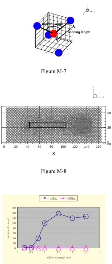
geometries of the structure were calculated. Figure M-7 illustrated the parameters of the tested structure. The bounding length and bound angle were tested. The testing atom formed six triangles with its four neighbors. Totally, six bonding angles and four bonding length were checked. The upper and lower of the bonds were listed in table MT-1. If all angles and bonding length were in the range, the center in the tetrahedron was marked as none damaged atom. Otherwise, the atom was considered as a damaged atom.
The depth of the damaged layer was estimated from the following procedure. The target region was as showed as Figure M-8. This region was in dimension of 60 A by 6 A. It was divided into 40 cells. Each cell had dimension of 3A by 3A. The damaged layer depth of each cell was the high difference of atoms. One is the highest damaged atom. The other one was the lowest undamaged atom. The final depth of damaged layer was the average of each depth of all cells.
結果
The study conducted two sets of simulations to examine the adhesion effect on the induced phenomena. First set was for pure rolling particle and the second one was for pure sliding particle. Seven levels of the adhesion were used in each set of simulation. The levels were 0.25, 0.5, 0.75, 1.0, 1.5, 2.0, and 2.5. The motions of work atoms induced by the particle were observed in all simulations. Besides, the material removal, induced surface roughness and the depth of the damaged layer were estimated in each simulation. The results showed that induced phenomena were affected both adhesion and the particle motion.
Motions of work atoms
atoms. Figure SR-0a showed morphology of the work atoms. The left figure was for sliding particle and the right was for the rolling particle. If the particle slid on the work surface, the work atoms seemed to be push away and laid the side of the trace. Besides, the work atoms piled up in the front of the particle possibly. If the particle rolled on the work surface, the work atoms seemed attached on the surface of the particle. However, little atoms piled up in the front of the particle compared with the sliding condition. The number of the atoms laid around the trace seemed less than the sliding condition also.
The cross-section perpendicular to the trace was different in two cases of particle motion. Figure SR-0bL was the cross-section induced by the sliding particle. The layout of the surface work atoms was conformal to the surface of the particle and became a semicircle type. At the edge of the semicircle, near the original surface of the work, there were obvious heap of work atoms. Figure SR-0bR was for the rolling case. The work atom didn’t form a semicircle layout. The cutting depth was apparently lower than in the case of sliding particle. Besides, there were no atoms heaps near the original work surface.
Figure SR-1 showed the relationship between adhesion and the material removal. For rolling particle, the material removal seemed to have a stepwise trend versus adhesive strength index. In the low adhesion, the removal was low and the material removal was high when adhesion was high. The tremendous change happened around 0.75 of adhesive strength index. The saturation in removal seemed recognizable in high and low adhesive strength index. For case of sliding particle, the material removal was always zero because the work atoms were not away from the surface indeed. Figure SR-2 showed the simulation of an instance for different adhesive strength levels under two kinds of particle motions. Fig SR-2a~c represented the high adhesion leaded to high material removal, when the particle was rolling. Compared with the rolling particle, Fig SR-2d~f showed no atoms adhered on the rear surface of the sliding particle. However, many atoms accumulated in the front of the sliding particle.
Figure SR-3 represented the induced surface roughness versus the adhesive strength index. For rolling particle, the roughness had a significant peak was at the index of 0.5. Figure SR-4 showed the simulation results of the rolling particle. When the adhesive strength index was 0.5, the surface was indeed rough than in other index. Figure SR-3 also showed the roughness trend versus different adhesive strength index for the sliding particle. In the low index range, the roughness rose with the increase of the adhesive strength index. In the high adhesion range, the roughness represented saturation trend. The rolling particle induced higher roughness than the sliding particle did. In addition, the intensity of adhesion effect on the roughness differed in two conditions. It was interesting that the highest roughness didn’t happen at the highest adhesive strength index.
Figure SR-6 showed the induced depth of the damaged layer under two condition of particle moving. It was special noted was the apparent depth difference between sliding and rolling particle. The depth induced by rolling particle was larger than that by the sliding particle at all adhesive strength indexes. Meanwhile, it seemed that the adhesion affected little on the depth induced by the sliding particle. However, the adhesion seemed to have affect on the depth if the particle rolled. It happened that an apparent local maximum on depth at 0.5 of adhesive strength
level. After reviewed the figure SR-4, the depth of damaged layer was especially high at the surface peak. At the same time, the depth had large variation in different locations. However, for other case of different adhesion level, the surface was smoother and the depth was more uniformed.
討論
It was shown the adhesion was the factor of induced phenomena. In this section, the possible way that adhesion and the particle motion affected the induced phenomena was discussed.
For rolling particle, the adhesion acted as a threshold on material removal. The motions of the rolling particle atoms created an environment to let adhesion take effect on material removal. The atom of rolling particle continuously left the work surface. It resulted the distance between atoms became larger and larger in the surroundings of the rear part of the particle. The
interaction became attraction among particle and work atoms in this area. If the attraction force between the work atom and the particle atom was larger enough than that between work atoms, the work atom would follow the particle atom. Thus, the work atom was trapped and an effective material removal occurred. Otherwise, the removal was not guaranteed or was zero. Hence, the removal was very low in the low range of the adhesion and increased apparently in the transient range. The trapped work atom would occupy a space of the particle surface whatever the adhesion was large or very large. Due to the particle surface was same in all simulation, the space allowed the work atoms to adhere was the same. Thus, the material removal saturated finally.
The rolling particle could bring the trapped work atom away from the work surface. It was the reason the rolling particle could remove the material. When the particle was rolling, the particle atom left the work surface continuously. Hence, the trapped work atom could leave the work. However, the sliding particle contacted the work surface with the same particle atoms always. Even the work atoms were trapped by the particle; they had no chance to leave the surface. Consequently, no material removal happened. A simulation replicated this
phenomenon showed as Fig DI-1. In the simulation, the particle moved above the surface in a very small angle. After a distance of moving, the particle adhered work atoms of different amount. More work atoms could be trapped on the particle if the inter adhesion was large. The results proved that as long as the trapped atoms had motion away from the work surface, the material removal could happen under the condition of sufficient adhesion.
Compared with the case of sliding particle, the high-induced surface roughness by rolling particle might due to the rolling particle pull-up work atoms easily. From the above statement, the rolling particle atoms continuously left the work surface. The work atoms were easily pulled up by rolling particle. When the atoms moved up more frequently, the surface was disturbed easily. However, the atoms on sliding particle had no up-and-down motion. The particle was difficult to bring the work atoms up. Hence, the induced surface roughness by sliding particle was less than by rolling particle.
The non-monotonic trend of roughness was from complex interaction between the work and particle in some adhesion range. The morphology of surface was result of interaction between particle and the work. According to the previous paragraph, when the interaction became attraction between particle and work, the surface atom would be pulled by the particle and the deeper layer work atoms. Roughly, two forces exerted on the surface atom. One was from the work and the other was from the particle. If these two forces were in the similar level, the position of surface atom might have large variation. For rolling particle as an example, the arrangement of atoms as Figure D-2a showed. At this time, the particle exerted more force on the surface atom than work atoms did. The surface atom followed the particle atom and was lifted. However, the lifted surface atom couldn't be removed because of insufficient force between particle and surface atom. The configuration would be as shown as figure D-2b. The resultant from the work was larger than the force between the particle and the surface atom. Hence, the surface atom stayed o the work. Due to the heightened position of the surface atom, the roughness was higher. On the contrary, if the attraction between particle and surface was very large than that between work and surface atom, the surface atom followed the particle easily. At the same time, the work had weak affection on the motion of the surface atom. Thus, the work atoms faced little force. The position of work atom was more stable. In this case, the surface atom would be removed. The work atom became the new surface. Consequently, the stable new surface atoms resulted in low induced surface roughness. On the other hand, if the force between particle and surface was too small, the particle couldn't affect the motion of the surface atom. Hence, the surface atom was in stable position. The roughness was still small.
For rolling particle, the appearance of peak in depth of damaged layer might have the same cause as the same as the induced surface roughness: the complex pulling on near-surface atoms by the particle and work atoms. In the previous paragraph, the non-monotonic trend of
roughness was due to the complex interaction between atoms. The near-surface atoms might be lifted but not removed. The lifted atoms might increase the depth of the damaged layer. Finally, the trend of depth of damaged layer had the same peak location as the induced surface roughness did. (Figure appendix)
Interesting phenomena happened when the particle slid on the surface although the adhesion affected little on the depth of the damaged layer. The height of work surface behind the sliding particle at low adhesion case was higher than that at high adhesion case. The possible reason might be the interaction between particle and work happened at deeper location if the adhesion was high. Because the center of particle was all the same for all adhesion case, the reasonable cause for this should be the size of the particle. By animating the series of simulation raw data, it was observed that as long as the work atoms adhered on the particle, the height of the work surface was lower. The possible reason for this was the adhesion between particle and the work atoms. The more adhesion make strong bound between particle and work atoms. Thus, the particle looked like larger and induced lower surface height.
The study restricted the particle in a sphere-like shape. In reality, the particle was not a sphere. The particle had very complicated shape and might cause phenomena that are more complex. These need advanced research. On the other hand, we observed there were atoms
piled in the front of sliding particle. This pile-up was similar to chip in cutting process, if the sphere particle was considered as a kind of tool. However, here was a major difference: the rack angle. For ordinary cutting tool, the rack angle was always positive. The rack angle was negative in our simulations. The tool with negative rack angle just pushed away atoms as showed as figure D-3a. Figure D-3b showed the atoms could move along the slope of the particle with positive angle. It seemed that the shape of the sliding particle was the key of material removal. It might need more studies.
The simulations suggested the polishing parameters should be selected according to the induced phenomena that we care. One set of parameters good for one induced phenomena might be harmful for other phenomena. For example, if the efficient material removal was welcome, the adhesion between particle and work atoms should be high and the particle had better roll on the work surface. However, if the damaged layer was a concern, that the particle slid on the work surface would be preferable. The study also suggested certain adhesion level brought
disadvantage and no advantages. For adhesive strength level of 0.5, it induced high roughness and insignificant material removal.
結論
The effects of adhesive strength between abrasive particle and work on various phenomena, induced by relative motion of particle on work, were studied. A goal of this study is to
understand the mechanism of polishing process when the size of abrasive particle is as small as several tens of nanometer. It was shown that the adhesive strength was an important factor in deciding the material removal capability of abrasive particle, the induced surface roughness and the depth of damaged surface layer. The study indicated that a sufficient large of adhesive strength was a requirement for a particle to effectively remove work material (atoms) when the particle rolled on work. An increase of adhesive strength may enhance the removal rate. However, such an increasing trend became significant when the adhesive strength was larger than a certain value. If the particle slid on work, a sufficiently large adhesive strength would not ensure the occurrence of material removal. The geometry of particle was the key factor in deciding whether a sliding motion of particle could result in material removal or not. Both the rolling and sliding motions of particle would leave surface irregularities on work. In general, the induced surface roughness due to rolling motion was larger than that due to sliding motion. The highest surface roughness always occurred at the circumstance that the adhesive strength between particle and work was on the verge to effectively pull the work atoms away. Finally, the transformation from defined structure to amorphous one for the atoms at the work’s surface layer was an unavoidable result due to particle motion on work. The average depth of such damaged layer from particle’s rolling motion was always larger than that from sliding motion. It was noted that the effect of adhesive strength did not reveal a significant influence on the average depth of damaged layer.
參考文獻
cutting of single crystal aluminum-effect of crystal orientation and direction of cutting,” Wear, 242 (2000), 60-88.
2. Y. Y. Ye, R. Biswas, J. R. Morris, A. Bastawros , and A. Chandra, “Molecular dynamics simulation of nanoscale machining of copper,” Nanotechnology, 14 (2003), 390396.
3. W. C. D. Cheong and L.C.Zhang, “Monocrystalline Silicon Subjected to Multi-Asperity Sliding: Nano-Wear Mechanisms,Subsurface Damage and Effect of Asperity
Interaction,” Int. J.Mat. and Prod. Tech., 18 (2003) , 398-407.
4. R. Komanduri, N. Chandrasekaran, and L. M. Raff, “Effect of tool geometry in nanometric cutting: a molecular dynamic simulation approach,” Wear, 219 (1998), 84-97.
5. L. C. Zhang and H. Tanaka, On the mechanics and physica in the nano-identation of silicon mono crystals,” JSME Int. J., Series A, 42(4) (1999), 45-53.
6. W. C. D. Cheong and L. C. Zhang, “Molecular dynamics simulation of phase
transformation in silicon mono crystals due to nano-indentation,” Nanotech., 11 (2000), 173-180.
7. W. C. D. Cheong and L. C. Zhang, “Effect of repeated nano-indentations on the deformation in mono crystalline silicon,” J. Mat. Sci. Lett., 19 (2000), 439-442.
8. 許政欽,奈米磨粒在工件上滾動所引發現象之探討:分子動力學法分析,2003,
中山大學碩士論文,高雄。
9. T. H. Fang, C. I. Weng, “Three-dimensional molecular dynamics analysis of processing using a pin tool on the atomic scale,” Nanotech., 11 (2000), 148-153.
10. K. Maekawa, and A. Itoh,” Friction and tool wear in nano-scale machining: a molecular dynamics approach,” Wear, 188 (1995), pp.115-122.
11. R. Komanduri, and N. Chandrasekaran, “Molecular dynamics simulation of atomic-scale friction” Phys. Rev. B, 61(20) (2000), 14007-14019.
12. L.C. Zhang, K.L. Johnson, and W.C.D. Cheong, “A molecular dynamics study of scale effects on the friction of single-asperity contacts,” Tribol. Lett., 10(1-2) 2001, 23-28.
10 20 Z 0 20 40 60 80 X 0 10 20 30 40 50 60 70 80 Y X Y Z Figure M-2 0 50 V2 0 10 20 30 40 50 60 70 V3 0 20 40 60 80 Y X Z A B C D Figure M-4 0 25 50 0 20 40 60 0 20 40 60 80 100 120 140 160 V1 Y X Z Figure M-5 Figure M-6
0 0.5 1 1.5 2 2.5 V3 0 1 2 V1 0 0.5 1 1.5 2 2.5 V2 X Y Z bonding length bonding angle Figure M-7 0 25 50 0 50 0 20 40 60 80 100 120 140 160 X X Y Z Figure M-8 0 20 40 60 80 100 120 140 160 0 0.5 1 1.5 2 2.5 3 adhesive strength ratio
number of removal
rolling sliding
0 0.2 0.4 0.6 0.8 1 1.2 1.4 1.6 0 0.5 1 1.5 2 2.5 3 adhesive strength ratio
Rq (埃 ) rolling sliding Figure SR-3 0 2 4 6 8 10 12 14 16 0 0.5 1 1.5 2 2.5 3
adhesive strength index
變質 層深 度 ( 埃 ) rolling sliding Figure SR-6 Particle atom Work atoms Figure D-2a Particle atom Work atoms Figure D-2b
Y X Z Figure D-3a 0 50 0 10 20 30 40 30 40 50 60 70 80 90 100 110 V1 Y X Z Figure D-3b