Ž .
Optics Communications 168 1999 195–200
www.elsevier.comrlocateroptcom
Frequency tracking and stabilization of a tunable dual-wavelength
external-cavity diode laser
L. Hsu
), L.C. Chi, S.C. Wang, Ci-Ling Pan
Institute of Electro-Optical Engineering and Department of Electrophysics, National Chiao Tung UniÕersity, Hsinchu 30010, Taiwan Received 8 April 1999; received in revised form 24 June 1999; accepted 29 June 1999
Abstract
We show a unique dual-wavelength external-cavity laser diode with frequency tracking capability and obtain a stable beat frequency between the dual-wavelength output. By using a Fabry–Perot interferometer as the frequency discriminator and the time-gating technique in a servo loop, the peak-to-peak frequency fluctuations were stabilized, with respect to the Fabry–Perot cavity, to 86 kHz in the dual-wavelength output at 802.5 and 804.5 nm, and to 17 kHz in their 0.9 THz beat signal. Similar performance was achieved for tuning of the dual wavelength separation ranging from 0.2 to 4 nm. q 1999 Published by Elsevier Science B.V. All rights reserved.
PACS: 40.60.P
Keywords: Dual-wavelength external-cavity semiconductor laser; Time gating; Frequency tracking; Frequency stabilization; Terahertz beat frequency
1. Introduction
Tunable external cavity semiconductor lasers
ŽECL. w x1 are important for an array of applications
Ž .
such as wavelength-division-multiplexed WDM op-tical communication, high-resolution spectroscopy and optical metrology. Frequency control of such
w x
lasers is often mandatory in practice 2 . On the other hand, an ECL capable of generating multiple wave-lengths is also desirable. An example of such lasers is the tunable continuous wave dual-wavelength
ex-Ž .
ternal-cavity laser 2-l-ECL as we demonstrated
w x
earlier 3,4 . The coaxial output of the two modes of
)
Corresponding author. Fax: q886-3-572-5230; e-mail: [email protected]
the 2-l-ECL produces an intensity-modulated signal
w x
at frequencies tunable beyond 7 THz 5 . This char-acteristic is ideal for applications such as the genera-tion of terahertz signal by optical heterodyne
conver-w x
sion or photomixing 6–8 , for which the two laser modes should be frequency-locked and stabilized. We have demonstrated stabilization of the output of a 2-l-ECL by locking one of the laser modes to a
w x
passive reference cavity 9 . A peak-to-peak fre-quency fluctuation of 4.2 MHz corresponding to a frequency stability of 1.14 = 10y8
was achieved. It is, however, not possible to determine whether the two modes fluctuate in frequency independently or in unison. In this paper, we show for the first time simultaneous frequency-tracking and stabilization of a tunable 2-l-ECL.
0030-4018r99r$ - see front matter q 1999 Published by Elsevier Science B.V. All rights reserved.
Ž .
2. Theory
The frequency tracking and stabilization of the dual-wavelength laser are realized because the two laser modes are coaxial. Consider two cavity-modes coaxial all over the cavity. The oscillating frequen-cies of the two cavity modes can be expressed by
n s p cr2 L and n s q cr2 L, where p and q are1 2
two integers, c is the speed of light in vacuum, and
L is the overall optical-path-length of the folded
external cavity. Differentiating n1 and n2 with re-spect to L gives
Dn1 Dn2 Dn y Dn2 1 D L
s s s y .
Ž .
1n1 n2
Ž
n y n2 1.
LAs L varies, n and n follow up in phase. The shift1 2
Dn21 of their beat frequency n s n y n21 2 1 is then subtractive: Dn s Dn y Dn . Substituting this into21 2 1
Ž .
Eq. 1 , we have, for n ( n 4 n ,1 2 21
Dn1 n1 s (1
Ž .
2 Dn2 n2 and Dn21 n21 s <1Ž .
3 Dn1 n1 Ž .Eq. 2 suggests the feasibility of the frequency tracking of two laser cavity modes in our
dual-wave-Ž .
length laser. Eq. 3 predicts that the beat frequency signal can be more stable than either cavity mode.
On the other hand, in the case of conventional heterodyne conversion involving two independent laser cavities, the fluctuations of n1 and n2 are random. The variation of the corresponding beat frequency becomes statistically additive: Dn2 sDn2
21 2
qDn2
. In other words, the beat signal of two inde-1
pendent lasers is less stable than that of a single 2-l-ECL.
3. Experimental
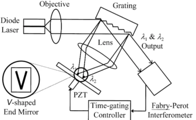
Fig. 1 illustrates the configuration of the tunable 2-l-ECL and the experimental set-up. The external-cavity diode laser consisted of a laser chip, an objec-tive lens, a grating, a lens, and a V-shaped end
Fig. 1. The laser configuration and experimental set-up. PZT: piezoelectric transducer.
Ž .
mirror. A broad area laser chip SDL-2430-C with a nominal wavelength l s 803.5 nm was used as theo gain medium. The laser chip has an anti-reflection
ŽAR coated front facet with a reflectivity of R f 5%. 1
Ž .
and high-reflection HR coated rear facet with R f2 95%, resulting in a threshold current of 250 mA. The diverging beam of the laser from the front facet was collimated by an objective lens with a focal length of 4.5 mm and NA s 0.47, then incident on a 45 mm =
Ž .
10 mm grating 1800 groovesrmm at an angle of 758. The first-order reflection of the grating at an angle of 298 was focused on the V-shaped gold-coated end mirror by an AR-coated lens with focal length of
f s 250 mm, as depicted in the inset of Fig. 1. The
angle of the V-shaped stripes was approximately 158, and each stripe has a width of 130 mm. The grating-lens-stripe mirror combination corresponds to an equivalent spectral filter of 0.25 nm. The external cavity reduced the threshold current to I s 230 mAth at l . At an operating current of 1.2 I , the lasero th output power was about 10 mW. As a result, the spectral separation of the two output wavelengths,
l sl y l , could be tuned by translating the
21 1 2
V-shaped end mirror vertically out of or into the plane of Fig. 1. Note that the two modes are coaxial inside the laser cavity except for a small portion near the two foci on the V-shaped end mirror. This makes frequency-tracked operation possible. The zeroth-order reflection of the grating provided the coaxial dual-wavelength output. The output beam was split twice by two beam splitters. The split beams were separately directed into a power meter, a spectrum
Ž .
Ž
interferometer Tech-Optics SA-2 with a free
spec-.
tral range n s2 GHz and finesse of 22 for
FSR
frequency stabilization and measurement.
For measurement of frequency stabilization of the 2-l-ECL, we employed the time-gating technique
w10 previously developed by us for a set of laserx
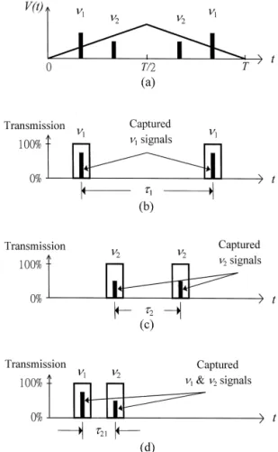
diodes. Because the laser is dominated by the exter-nal-cavity modes with little influence by the laser chip’s own modes for operating current I F 1.2 I ,th the time-gating technique is applicable only on the external-cavity modes in this experiment. The basic principle of the time-gating technique is illustrated in Fig. 2. A triangular waveform voltage is used to scan the Fabry–Perot interferometer at a scanning rate of
Ž .
400 Hz, as shown in Fig. 2 a . The amplitude of the scanning waveform is adjusted such that half of the
Ž .
Fig. 2. Operating principle of time-gating technique. a scanning
Ž .
waveform and two laser-mode signals; b a pair of time-gating
Ž . Ž .
pulses for t ; c a pair of time-gating pulses for t ; d a pair of1 2
time-gating pulses for t .21
scanning period Tr2 covers one free spectral range
nFSR of the Fabry–Perot interferometer. This allows
the two laser frequencies n and n to appear twice1 2 within each period. A pair of time-gating pulses is then used to capture the two n signals per period, as1
Ž .
shown in Fig. 2 b . Since the laser signals at n and1
n2 have a linewidth limited by the Fabry–Perot interferometer to about 90 MHz, thus the gating pulse width is typically adopted to only twice the width of the laser signals, which is about hundreds of megahertz, to prevent capturing the adjacent laser signals. As frequency n shifts, the duration between1 the two captured signals changes. It should be pointed out that the duration t is measured as the separation1 in time between the two peaks of the captured n1 signals, which is extracted from the center zeros of the first derivatives with respect to time. Therefore, the duration is relatively accurate and independent of the Fabry–Perot bandwidth.
In practice, the duration t between the peaks of1 the two captured n signals is then converted into a1 voltage signal V s kt , where k is a constant. Simi-1 1 larly, the duration t between the peaks of the two2
Ž .
captured signals of n , as shown in Fig. 2 c , is2 converted into V . Consequently, for any fluctuations2 in laser frequency n and n , the voltage signal V1 2 i
Ž . Ž .
will vary according to Dn s DV rk P ni i FSRrT ,
where Dn and DV are the fluctuations in n and V ,i i i i
respectively, for i s 1 and 2. We also measure a third voltage signal V s kt , which provides in-21 21 formation on fluctuations in the difference frequency
n21sn y n2 1 according to the relationship Dn s21 ŽDV rk P 2n21 . Ž FSRrT . Here t. 21 is the duration
be-tween the peaks of the captured signals n and n1 2
Ž .
within the same half-periods, as shown in Fig. 2 d . Either V or V was then sent into a proportional-in-1 2
Ž .
tegral-differential PID controller. The output of the PID controller is used to drive a piezo-electric
trans-Ž .
ducer PZT mounted behind the V-shaped end mir-ror for laser frequency stabilization of one cavity mode.
4. Results
The frequency tracking capability and stability of the laser modes was obtained by converting the three fluctuating voltage signals DV , DV and DV1 2 21 into
Dn , Dn1 2 and Dn21 as given above. It should be noted that all the frequency fluctuations thus
mea-sured were referenced with respect to the Fabry– Perot interferometer, which is reasonably stable
dur-Ž . Ž
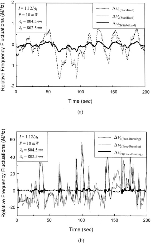
Fig. 3. a Relative frequency fluctuations as a function of time for Dn , Dn , and Dn1 2 21with stabilization l s 804.5 nm and l s 802.51 2
. Ž . Ž
nm ; b relative frequency fluctuations as a function of time for Dn , Dn , and Dn1 2 21 without stabilization l s 804.5 nm and l s1 2
.
ing the measurement period. Hence, the measured frequency stabilities of n , n1 2 and n21 are relative frequency stabilities. At an operating current of 1.2
Ž .
I , Fig. 3 a shows the converted Dn , Dn , andth 1 2
Dn , under stabilized conditions, as a function of21
time during a 200 s scan with a sampling interval of 0.5 s. The wavelengths l s 804.5 nm and l s1 2 802.5 nm of the two oscillating modes were directly determined from the spectrum analyzer with a reso-lution of 0.1 nm. The side mode suppression ratio
ŽSMSR of the laser output was better than 10 dB.. Ž .
For comparison, Fig. 3 b shows the same signals for laser without stabilization. As can be seen from the results, the peak-to-peak fluctuations are 2 MHz with stabilization and 80 MHz without stabilization. The two fluctuation signals Dn1 of l1 and Dn2 of l2 were nearly the same and synchronous, indicating fairly good tracking of the two oscillating wave-lengths. With stabilization, the square root of the
w x ² :
Allan variances 11 for the two modes is Dn (
1
²Dn :s86 kHz, corresponding to a relative
fre-2
² : ² :
quency stability of Dn rn ( Dn rn s 2.3 =
1 1 2 2
10y1 0
. As for the beat signal at n s 0.93 THz, the21 fluctuation is relatively small. The square root of the
² :
Allan variances of n21 is Dn21 s17 kHz. In
addi-² :
tion, we also measured Dn21 at a fixed total output power as a function of the separation of the two wavelengths, l s l y l , for a tuning range of21 1 2 0.2 nm F l F 4 nm, as shown in Fig. 4. It can be21
² : Ž .
seen that Dn21 s 17.2 " 0.4 kHz, which is nearly
independent of the separation between the two wave-lengths within the above tuning range.
Fig. 4. Relative frequency fluctuations Dn21 as a function of l21
Žsl y l1 2.over the range 0.2 nm Fl F 4 nm.21
5. Discussion
For a perfect frequency tracking condition be-tween the two oscillating modes, we would expect
Dn21 to be very small. However, our data shows
Ž .
Dn21) Dn y Dn , which suggests a slight effect2 1 of partially laser cavity dependent of the two oscillat-ing modes n and n . This may be attributed to the1 2 fact that the two coaxial modes are not perfectly coaxial within the entire cavity. In fact, the two modes do separate apart from each other within a relatively short distance between the lens and the V-shaped end mirror, as shown in Fig. 1. Denoting
L and L as the overall optical-path-lengths of the1 2
cavities for the two modes separately, we have
Dn rn s yD L rL and Dn rn s yD L rL . As-1 1 1 1 2 2 2 2
suming that D L and D L fluctuate simultaneously,1 2 we may set D L s bD L , where b is a constant. For1 2
n ( n , L ( L , and Dn ( Dn y Dn1 2 1 2 21 2 1 in this
Ž .
work, we obtain Dn s 1 y b Dn . Substituting 1721 2 kHz for Dn , 86 kHz for Dn , 3.74 = 1014 Hz for
21 2
n , and 75 cm for L2 2 into the above expressions
˚
˚
yields b s 0.8, D L s y1.7 A, and D L s y1.4 A,2 1
˚
< <
indicating a difference of D L y D L s 0.3 A in1 2 cavity length variation. This is reasonable since the V-shaped end mirror was mounted on the top of a moving PZT. The random fluctuations in the cavity lengths due to environmental vibration noise can be considered as the major factor in preventing the perfect frequency tracking between the two modes in the duel-wavelength laser. Furthermore, since the frequency instability induced by the cavity length fluctuations is frequency independent, this is in qual-itative agreement with the plot of Dn21 as seen in Fig. 4. We believe that the frequency tracking capa-bility and noise reduction in the 2-l-ECL can be improved by increasing the rigidity of the V-shaped end mirror and its mount.
6. Summary
We demonstrated the tracking capability and rela-tive frequency stability of two coaxial oscillating modes in a dual-wavelength external-cavity laser using a time gating technique and a Fabry–Perot interferometer as the frequency discriminator. When the laser was stabilized against a reference Fabry– Perot interferometer, the peak-to-peak fluctuations of
the laser frequencies were able to be stabilized to 86 kHz in the dual-wavelength output at 802.5 nm and 804.5 nm, and to 17 kHz in their 0.9 THz beat frequency signal. The frequency-tracking characteris-tic of the 2-l-ECL results in a factor of five im-provement in the relative frequency stability for the beat signal of the two modes. It is nearly indepen-dent of the separation between the two wavelengths
Ž .
for 0.2 nm F l s l y l F4 nm. With this
21 1 2
unique frequency tracking capability, the 2-l-ECL should be an ideal light source for applications such as heterodyning or photomixing for the generation of tunable terahertz radiation.
Acknowledgements
This work was supported in part by various grants of the National Science Council of the Republic of China.
References
w x1 F.J. Durate, et al., Tunable Laser Applications, Marcel
Dekker, New York, 1995.
w x2 M. Ohtsu, et al., Frequency Control of Semiconductor Lasers,
Wiley, New York, 1996.
w x3 C.-L. Wang, C.-L. Pan, Appl. Phys. Lett. 64 1994 3089.Ž . w x4 C.-L. Pan, C.-L. Wang, Opt. Quantum Electron. 28 1996Ž .
1239.
w x5 C.-L. Wang, C.-L. Pan, Opt. Lett. 20 1995 1292.Ž . w x6 E.R. Brown, K.A. Mcintosh, K.B. Nichols, C.L. Dennis,
Ž .
Appl. Phys. Lett. 66 1995 285.
w x7 R. Paiella, K.J. Vahala, IEEE J. Quantum Electron. 32 Ž1996 721..
w x8 N. Onodera, Electron. Lett. 32 1996 1013.Ž .
w x9 C.L. Pan, Y.P. Lan, S.C. Wang, CLEO’97, Tech. Digest II,
Paper CWF29, 244, 1997.
w10 P.-Y. Chien, C.-L. Pan, Opt. Commun. 83 1991 81.x Ž . w11 D.W. Allan, Proc. IEEE 54 1966 221.x Ž .