Implementation of an active headset by using the H
`robust
control theory
Mingsian Bai and Dunjay Lee
Department of Mechanical Engineering, Chiao-Tung University, 1001 Ta-Hsueh Road, Hsin-Chu 30050, Taiwan, Republic of China
~Received 27 August 1996; revised 4 April 1997; accepted 29 May 1997!
This paper presents a methodology for implementing an active headset by using H`robust control theory. The adopted structure is feedback tracking control. Performance, stability, and robustness of the closed-loop system have been taken into account in the design procedure by using a general framework of the H`theory. The resultant controller is realized on the basis of operational amplifier circuitry. Experiments are conducted to test the developed headset. The result shows that the headset achieves broadband attenuation up to approximately 15 dB in the band 200–800 Hz. The design considerations indicated in the experimental result are also addressed. © 1997 Acoustical Society of America.@S0001-4966~97!05709-3#
PACS numbers: 43.50.Ki, 43.38.Si@GAD#
INTRODUCTION
The active noise control ~ANC! technique has been an active area in acoustics since Lueg filed his patent.1Research efforts have been attempted to put this emerging technology into a great variety of applications, such as headsets, active duct silencers, active noise cancelers in vehicles or aircraft cabins, and so forth.2–4Among the ANC applications, active headsets can be regarded as the most mature and practical from a commercial standpoint.
As opposed to the feedforward control widely used in active duct silencers, feedback control structure is adopted for the design of active headsets. The reason for this is partly because the upstream reference is usually unavailable and partly because the system order is sufficiently low for feed-back control to be practical in broadband noise rejection. The conventional design of the controller for active headsets can be dated back to Olson and May,5 and also Wheeler.6Their designs were based on classical frequency-domain compen-sation that relies heavily on heuristically shaping the open-loop frequency response with acceptable margins.
In contrast to the classical compensation, the H`robust control theory based on two Riccati equations~the so-called 1988 approach! is employed in the paper for controller syn-thesis because it not only provides a unified framework for all control structures, but also yields controllers with guaran-teed margins.7–12In addition, the H`theory reveals physical insights into the perturbations and uncertainties of models resulting from system identification, aging of electronic com-ponents, environmental changes, nonlinearity, and drifting of acoustic system properties that usually arise in practical ap-plications. These factors might cause deterioration of perfor-mance or even of stability. It is then highly desirable to de-velop an ANC controller capable of accommodating these detrimental effects. To this end, the H` control theory is employed in this study to meet the requirement of robust performance and robust stability optimally in the face of plant uncertainties by choosing proper weighting functions.
The H`controller is realized on the basis of operational
amplifier circuitry to avoid unnecessary time delay that might cause undesired degradation of performance and even stability of the system. Experiments are then conducted to test the developed headset. The result shows that the headset proves to be robust in attenuating broadband noises. The design considerations indicated in the experimental results are also addressed in the conclusion.
1. THEORETICAL BACKGROUND A.H` robust control theory
A brief review of the H` robust control theory is given in this section. The following derivation contains a fair amount of mathematical definitions and results. Because the H` theories can be found in much control literature,7–12we present only the key ones needed in the development of the ANC algorithm. The rest are mentioned without proof. In addition, since the system model is identified by a parametric procedure in discrete-time domain, we present only the discrete-time H`algorithm.
In modern control theory, all control structures can be described by using a generalized control framework, as de-picted in Fig. 1. The framework contains a controller C(z) and an augmented plant P(z). The controlled variable v(k)
corresponds to various control objectives z1(k), z2(k), and
z3(k), and the extraneous input w(k) consists of the
refer-ence r(k), the disturbance d(k), and the noise n(k). The signals u(k) and e(k) are the control input to the plant and the measured output from the plant, respectively. The gen-eral input–output relation can be expressed as
F
V~z! E~z!G
5F
P11~z! P12~z! P21~z! P22~z!G
F
W~z! U~z!G
5Pg~z!F
W~z! U~z!G
, ~1! where the submatrices Pi j(z), i, j51,2 are compatiblepar-titions of the augmented plant Py(z) and the symbols are
The rationale of the H`control is to minimize the infin-ity norm of the transfer function Tvw(z) betweenv(k) and
w(k), which can be expressed by the linear fraction trans-formation~LFT! as
Tvw~z!5LFT~Pg~z!,C~z!!5P11~z!1P12~z!C~z!
3@12P22~z!C~z!#21P21~z!. ~2!
Hence, the mathematical statement of the optimal H` prob-lem reads min C~z!iTvw~z!i` 5min C~z! sup 0<u,2p iTvw~eju!i. ~3!
However, instead of finding the optimal solution, which is generally very difficult, one is content with the suboptimal solution that can be analytically obtained. This becomes the so-called standard H` problem: finding C(z) such that
iTvw(z)i`,1. Insomuch as a control problem is cast into the
generalized framework, an optimal controller can be synthe-sized by many H` algorithms. The available algorithms can be divided into two classes: the model matching algorithms
~the 1984 approach! and the two Riccati equation algorithms ~the 1988 approach!. In the study, we use the latter approach,
which does not require a chain of factorizations as in the former approach, and thus numerical problems in handling high-order ~acoustical! plants can be minimized. Since the computational algorithm contains lengthy algebraic defini-tions and expressions that are standard in control literature, but are not the emphasis of this paper, we simply refer to Ref. 12 for details.
B. Feedback control structure
In this section, an analysis is carried out for a typical feedback structure ~Fig. 2! on the basis of the aforemen-tioned generalized control framework. The symbols P1(z)
and P2(z) correspond to the primary~disturbance! path and
the secondary ~control! path, respectively. To find an H` controller, we weight the sensitivity function S˜(z) by W1(z),
the control input u(k) by W2(z), and the complementary
sensitivity function T˜(z) with W3(z), where the sensitivity
function and the complementary sensitivity function are de-fined, respectively, as13
FIG. 1. Generalized control framework.
FIG. 2. Feedback ANC structure.
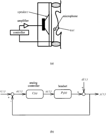
FIG. 3. The H` active headset system.~a! Experimental setup; ~b! block diagram.
FIG. 4. Frequency response functions of the headset. ~a! Three example headset models ~nominal plant ———; perturbed plant 1 -•-•; perturbed plant 2 ...!; ~b! multiplicative plant perturbations DP1andDP2versus the
inverse of the weighting function W321(s) @W321(s) ———; DP1 -•-•;
S
˜~z!511P2~z!C~z!1 ~4!
and
T
˜~z!511PP2~z!C~z!2~z!C~z!. ~5! Note that S˜(z)1T˜(z)51. To achieve disturbance rejection and tracking performance, the nominal performance condi-tion must be satisfied,
iS˜~z!W1~z!i`,1. ~6!
Note that the notations W1(z), W2(z), and W3(z) denote the
Z transform of weighting functions which should not be con-fused with the extraneous input w(k) in Fig. 1. On the other hand, for system stability against plant perturbations and model uncertainties, the robustness condition derived from the small-gain theorem10must be satisfied,
iT˜~z!W3~z!i`,1. ~7!
In common practice of loop shaping, W1(z) is chosen as a
lowpass function and W3(z) is chosen as a highpass func-tion. It is well-known that the trade-off between S˜(z) and T
˜(z), in conjunction with the waterbed effect, dictates the performance and robustness of the feedback design. This classical trade-off renders the so-called mixed sensitivity problem:11
iuS˜~z!W1~z!u1uT˜~z!W3~z!ui`,1, ~8!
which is also a necessary and sufficient condition for the controller to achieve both nominal performance and robust stability.
In terms of the generalized control framework, the input–output relation of the augmented plant corresponding to the feedback structure is
F
Z1~z! Z2~z! Z3~z! E~z!G
5F
W1~z! 2W1~z!P2~z! 0 W2~z! 0 W3~z!P2~z! 1 2P2~z!G
F
D~z! U~z!G
. ~9!Hence it can be shown by LFT that the suboptimal condition of the feedback controller reads
I
F
W1~z!S˜~z! W2~z!S˜~z!C~z! W3~z!T˜~z!G
I
`
,1, ~10!
where S˜(z) and T˜(z) are defined in Eqs. ~4! and ~5!, and R~z!5 C~z!
11P2~z!C~z!. ~11!
With reference to Eq. ~9!, the H` controller can then be found via the synthesis procedure outlined in Ref. 12.
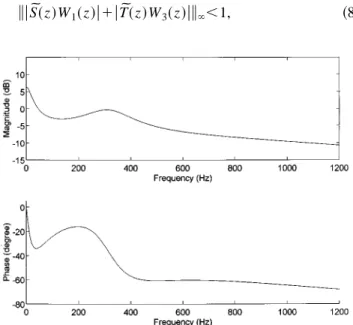
FIG. 5. Frequency response function of the H`active headset controller.~a! Magnitude~dB!; ~b! phase ~deg!.
FIG. 6. Loop shaping of the unity feedback control design for the active headset.~a! W121(s)••• vs S˜(s) ——— ; ~b! W321(s)••• vs T˜(s) ——— .
TABLE I. The plant model of the headset identified by the ARX procedure.
Zeros Poles a23.0841 0.661260.3483i a1.0320 20.442660.3324i 20.4387 0.0034 Gain50.3921 a
Denotes nonminimal phase zeros.
TABLE II. The controller model for the headset obtained by the H` syn-thesis procedure. Poles (3104) Zeros (3105) 22.0959 23.4362 21.6790 20.132760.1302i 20.8121 20.1885 20.059260.1973i 20.0361 Gain50.1623
II. EXPERIMENTAL INVESTIGATIONS
Experimental investigations were conducted to verify the practicality of the H`controller synthesis technique. The technique was employed to design an active headset. A head-set generally has small acoustical volume, which implies the associated model is usually of low order. This is a desirable property that admits the use of feedback control structure for broadband noise rejection.
The experimental setup and the corresponding block
dia-gram are illustrated in Fig. 3. Note that the primary path, P1(z), is simply taken as unity in this case. The earcup of
the headset is lined with some fiberglass sound-absorbing material to provide appropriate damping for the system. The importance of passive damping, an often overlooked factor in active design, lies not only in high-frequency attenuation but also system robustness against plant uncertainties.14With proper damping treatment, the plant can be gain-stabilized even with poorly modeled or unmodeled flexible modes. An-other benefit of passive damping is that a lower order of plant model than the lightly damped plants can usually be obtained, so that numerical error can be reduced.
The relative position of the sensor and actuator is an-other important issue. In the experiment, the sensor ~a ca-pacitor microphone! is placed in the close vicinity of the control loudspeaker to form the so-called collocated control. In doing so, the waterbed effect, in conjunction with non-minimal phase zeros and time delay, can be alleviated.10,13In what follows, the design procedure will be carried out in terms of performance, stability, and robustness of the closed-loop system.
Prior to controller design, the mathematical model of the plant has to be established via an ARX system identification procedure.15In practical situations, the acoustical plant of the headset may differ from person to person. In the experiment, three testees are asked to wear the headset to give three plant models, as shown in Fig. 4~a!. One of the models is taken as the nominal and the others are taken as the perturbed plants. This figure gives us the general idea of the size of plant uncertainty. The poles and zeros of the nominal plant are included in Table I. Note that the model is of very low order
~54 in this case!. The plant uncertainty can be
accommo-dated by choosing a suitable weighting function, W3, with sufficient high-frequency roll-off in H` design. The plant uncertainties and the chosen weighting function, W3, are
illustrated in Fig. 4~b!. After the weighting function, W3, has been chosen for robustness, we then choose W1as a lowpass
function for loop-shaping the nominal performance in the closed-loop feedback design.
On the basis of the identified plants, the aforementioned H` synthesis procedure is employed to calculate the optimal controller. The frequency response function of the resultant H` controller is shown in Fig. 5. The weighting functions W1 and W3 used for the H` design, and the resultant
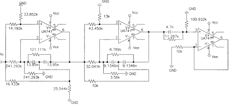
sensi-tivity function and the complementary sensisensi-tivity function of the unity feedback system, are shown in Fig. 6. Note that the sensitivity functions are bounded by the reciprocals of the weighting functions, as required by the H`design procedure. Taking into consideration the cost of the headset and time delay of common digital systems that might cause undesired degradation of performance and stability, we choose to implement the H` controller by analog filters. Hence, the discrete H`controller is converted into a continuous equiva-lent by bilinear transform. The transfer function of the result-ing analog controller is tabulated in Table II. The H` con-troller is then implemented by using operational amplifier circuitry. To be more specific, the transfer function of the controller is first converted into a cascade form composed of first- and second-order templates, as shown in Fig. 7. The FIG. 7. Templates of operational amplifier circuit.~a! First-order circuit; ~b!
formula for the first- and second-order templates, respectively, are Vout~s! Vin~s! 5A s11/R1C s1~1/R1C11/R1C! ~12! and Vout~s! Vin~s! 5 rs21s$r@2~G11G3!1G2#2aG222bG3%/C1@rG2~G11G3!2bG2G3#/C2 s212~G1/C!s1~G1G2/C2! , ~13!
where Gi51/Ri, i51,2,3. A general practice is to pair the
poles and the zeros in a stage as closed to each other as possible so that the frequency response is equalized. In ad-dition, the gains of all filter stages should be uniformly dis-tributed to minimize noise amplification. A more detailed description of the implementation of analog filters can be found in Ref. 16. According to this procedure, the foregoing fifth-order H` controller is implemented by cascading one first-order stage and two second-order stages
C~s!50.7046s 212.44663105s18.74473108 s211.18383103s14.24303106 30.2303s 216.11313103s17.95843107 s212.49123104s11.36363108 3s11.8851310 4 s12.09593104. ~14!
Common operational amplifiers such as ua741 or high-impedance field-effect transistor ~FET! operational amplifi-ers TL074 can be used in the implementation of the above transfer function. The resulting circuit diagram is shown in Fig. 8.
Figure 9 shows the open-loop gain before and after the active compensation. Before compensation, although the gain margin is infinite and the gain crossover frequency is
5034 Hz, the phase margin is only 35.80 deg, as shown in Fig. 9~a!. Thus, the system is apparently not robust enough to cope with plant perturbations. However, after compensation, the phase margin in Fig. 9~b! is raised to 82.32 deg at the gain crossover frequency 575 Hz, and the gain margin be-comes 15.13 dB at the phase crossover frequency 2460 Hz. The robustness is indeed improved by the compensation. In addition, the compensated system also has acceptable gain margin of 15.23 dB and phase crossover frequency of 2460 Hz. Figure 10 shows the experimental results for rejecting a Gaussian white noise by using the headset before and after the active control is activated. From the result, it can be observed that broadband attenuation up to approximately 15 dB has been achieved in the frequency range 200–800 Hz.
In addition to noise rejection, the active headset is also designed for tracking external command signals. In Fig. 11, the closed-loop transfer function between command input and the plant output remains approximately flat within 100– 865 Hz, and the phase remains almost linear between 100 and 900 Hz. To test the tracking performance, the headset is used for listening to pop music in a noisy environment. Fig-ure 12 shows the sound received by the embedded micro-phone, with and without the active control. The result sug-gests that the active headset indeed produces satisfactory performance of signal tracking in conjunction with noise re-jection.
III. CONCLUSION
An active headset has been implemented by using H` robust control theory. Performance, stability, and robustness of the feedback system have been taken into account in the
design procedure by using a general framework of the H` theory. Robust margins are satisfied, in addition to nominal performance. This is vital in practical applications, where system uncertainties are present. Because feedback control is used, no reference input is needed, so that the acoustic feed-back problem can be avoided. The common impression that feedback control is not suitable for broadband noise attenu-ation does not apply to this case, in which the plant is of very low order (54). The resultant controller is realized via op-erational amplifier circuitry. The experimental results show that the active headset is effective in tracking external com-mand signals and rejecting broadband noise.
Some crucial factors, including small acoustical volume, proper passive damping treatment, and collocated arrange-ment of the microphone and the speaker, must be taken into account in designing the active headset. We should be able to FIG. 9. Open-loop transfer function of the headset with and without the
active control.~a! Without active control; ~b! with active control.
FIG. 10. Sound pressure power spectra in the headset cavity with and with-out the active control. Active control off ——— ; active control on••• .
FIG. 11. Transfer function T˜(s) between the command input and the plant output of the closed-loop system for the active headset.~a! W321(s)••• vs
T
˜(s) ——— ; ~b! phase of T˜(s).
FIG. 12. Tracking performance of the headset to a pop music exposed to white noise environment.~a! Command signal ——— versus corrupted sig-nal received in the headset without active control•••; ~b! command signal ——— versus signal received in the headset with active control••• .
improve the performance of the headset further if the physi-cal configuration is optimized for the active control purpose. This aspect will be explored in future research.
ACKNOWLEDGMENTS
This paper is written in memory of the late Professor Anna Pate, Iowa State University. Special thanks also go to Professors F. B. Yeh and M. C. Tsai for the helpful discus-sions on the H` control theory. The work was supported by the National Science Council in Taiwan, Republic of China, under the project number NSC 83-0401-E-009-024.
1P. Lueg, ‘‘Process of silencing sound oscillations,’’ US Patent No.
2,043,416~1936!.
2S. J. Elliot and P. A. Nelson, ‘‘Active noise control,’’ Noise News Int. 2,
75–98~1994!.
3M. O. Tohki and R. R. Leitch, Active Noise Control~Clarendon, Oxford,
1992!.
4C. R. Fuller and A. H. von Flotow, ‘‘Active control of sound and
vibra-tion,’’ IEEE Control Systems Magazine 15~6! ~December 1995!.
5
H. F. Olson and E. G. May, ‘‘Electronic sound absorber,’’ J. Acoust. Soc. Am. 25, 1130–1136~1953!.
6P. D. Wheeler, ‘‘Voice communication in the cockpit noise
environment—the role of active noise reduction,’’ Ph.D. thesis, University of Southampton, England, 1986.
7J. C. Doyle, K. Glover, P. Khargonekar, and B. A. Francis, ‘‘State space
solution to standard H2and H` control problems,’’ IEEE Trans. Autom.
Control. 34„8…, 832–847 ~1989!.
8P. A. Iglesias and K. Glover, ‘‘State-space approach to discrete-time H
`
control,’’ Int. J. Control 54, 1031–1073~1991!.
9
I. Yaesh and U. Shaked, ‘‘Transfer function approach to the problems on discrete-time systems: H`-optimal linear control and filtering,’’ IEEE Trans. Autom. Control. 36, 1264–1271~1991!.
10J. C. Doyle, B. A. Francis, and A. R. Tannenbaum, Feedback Control
Theory~Macmillan, New York, 1992!.
11F. B. Yeh and C. D. Yang, Post Modern Control Theory and Design
~Eurasia, Taiwan, 1992!.
12M. C. Tsai and C. S. Tsai, ‘‘A transfer matrix framework approach to the
synthesis of H`controllers,’’ Int. J. Control 5, 155–173~1995!.
13G. F. Franklin, J. D. Powell, and A. Emami-Naeini, Feedback Control of
Dynamic Systems~Addison-Wesley, Reading, MA, 1994!.
14R. Gueler, A. H. von Flotow, and D. W. Vos, ‘‘Passive damping for
robust feedback control of flexible structures,’’ J. Guid. Control. Dyn.
16„4…, 662–667 ~1993!.
15L. Jung, System Identification: Theory for the User~Prentice-Hall,
Engle-wood Cliffs, NJ, 1987!.
16R. Schaumann, M. S. Ghausi, and K. R. Laker, Design of Analog Filters