Effect of Grating Detuning on Volume Holographic Memory using
Photopolymer Storage Media : Reflection holograms
Mei-Li Hsieh, Ken Y. Hsu, and Pochi Yeh*
Institute of Electro-Optical Engineering
National Chiao Tung University
Hsin-Chu, Taiwan
R.O.C.
FAX: 886-3-571-6631
E-Mail: [email protected]
*Depament of Electrical and Computer Engineering
University ofCalifornia at Santa Barbara
Santa Barbara, California 93 106
U. S.A.
Abstract
We present a study of the grating detuning effect on the volume holographic data storage using photopolymer recording
material. By using the Bragg matching condition, the angle shift and the decay of the diffraction efficiency of the
reconstructed beam is obtained. Then the distortion of the readout page is described. And a method for pre-compensation of the incident angles of the reading beam is presented.
Keywords: Bragg Detuning; Holographic memory; Volume holograms
I. Introduction:
Holographic data storage has been considered as one of the next generation information storage technologies because of its distinct advantages of large storage capacity and fast data access rate [1-3]. The development of suitable recording material remains one of the central challenges in the area of holographic data storage. So far, the most popular materials for volume holographic storage are photorefractive crystals and photopolymers. Photorefractive crystals have been the traditional experimental choice because of its excellent dimensional stability and optical quality. However, it suffers from small dynamic range and low photosensitivity. Photopolymer materials are especially interested because these materials with different compositions are relatively easy to be synthesized. Also, they can be designed to have large index contrasts (znO.Ol) and high photosensitivity (lO—104J/m2)[4]. However, these materials have a disadvantage, which is called the shrinkage (or expansion) effect. These are the dimensional changes induced by the chemical reactions during the holographic recording procedure such that the recorded refractive index grating has different grating spacing from that of the light interference fringes. As a result, the Bragg condition for volume holograms is lost and the recorded information cannot be readout completely.
In this paper, we present a study of the grating detuning effect on the volume holographic data storage using
photopolymer recording material. By using the Bragg matching condition, the angle shift and the decay of the diffraction efficiency of the reconstructed beam is obtained. Then we discuss the distortion of the readout data page. Finally, a method for pre-compensation by deviating the incident angles of the reading beam from the original writing beam will be proposed.
II. Theoretical Analysis:
1. AngIe shift of the reconstructed beam and the degrading of the diffraction efficiency:
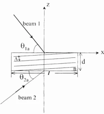
Firstly, we consider the shift of Bragg angle due to the changes in the refractive index and the shrinkage of the recording material for the reflection hologram. The schematic diagram of the geometry for the reflection holographic recording is shown in Figure 1 .Inthe figure, the angles eia and 02aarethe angle between beam 1 and beam 2 measured
is the object beam. Let the original thickness of the recording medium be d and the lateral dimensions be 1. X is the
wavelength for recording and reading lights, and n is the refractive index of sample before recording. Two recording beams were incident into the medium and form an interference pattern. The interference pattern can be stored in the medium and the grating wave vector can be written as:
1?
=(sinO+cos80I)
(1)where O
= (
—°2 )/2,
A
is the grating spacing and is given byA=
(2).
(0+6
2nsin '
2whereO and 02arethe incident angles of the recording beam 1 and beam 2 inside the medium, respectively. According to the Snell's law, they can be written as 9 =cos'(cos(6')/n)
and 2
= coc(cos(o2a)/n).Assume that after the holographic grating has been recorded, because of the shrinkage effect, the material dimensions have changed to (i +ad) .d and (1 +a1
)
1 , andthe refractive index of the material has changed to (i +a,)
ii,where ad, a1 and a are the dimensional shrinkage and index change rate of the material, respectively. Then, the grating vector will be changed toRt2ff1is& +
1cos9 2
(3)A 1+a1
°l+ad
°)
Thus, the Bragg matching condition has been changed. If we consider the reading beam being incident at the angle identical with that of the original reference beam 1 ,thenthere is a phase mismatch .K, which can be written as:
AK
= {— [(i
+ a )nr
— cos2a
+ad
[s 0 + s 2
][(i + a )nr
—
[cos 8a+
(cos &2a
cos6a)] }
Asa result, the diffracted angle will be shift from the Bragg matched case, and diffraction efficiency of the reconstructed beam will also be degraded. The shift ofthe diffracted angle and its diffraction efficiency can be derived as following:
K51flh2(S .t)
'I— 2 (5)
s2
cosh2(s .t)÷t4i) 5j2(5
.t)0d
cos1cos+ (cos 02
cos6a)
_ 2 (6)1+a1
)
I
2 (\2
irAnwhere s = I K — I
I and K =
\!
2)
22sin
By Eq.(6), it is seen that the diffracted angle is only dependent on a1. Assume that the shrinkage parameters of the material
are the following : a1 0, ad =—1%
and a =
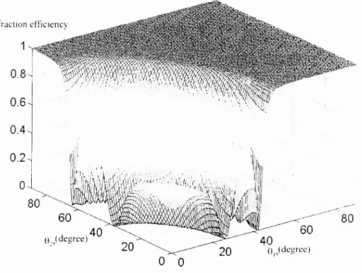
1%.Also,the thickness of the material is assumed to be lOOim. According to Eq.(6), the shift of the diffracted angle is equal to zero, which means that the diffracted angle remains not changed if there is no shrinkage along the transverse dimension of the recording material. However, the diffraction efficiency will be degraded and it depends on the recording angles 0la and 02aThesimulation results are shown in Figure 2. This figure shows that the diffraction efficiency is degraded significantly for the ranger of °ia 0 90° and 2a 0—9O'.Hence, in order to obtain
high and uniform diffraction efficiency, we should choose the appropriate recording angles for the hologram.
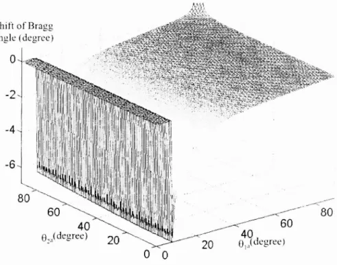
On the other hand, if there is shrinkage along the transverse dimension of the recording material, i.e. a1 0 ,thenboth the diffracted angle and diffraction efficiency are changed. Assume a1 =—1%, then the computer simulation results are shown in Figure 3. Figure 3a shows the relationship between the diffraction efficiency and the incident angles of the recording beams. Figure 3b represents the diffracted angle as a function of the recording angles. It is seen that the diffracted angle shifts significantly and the value of angular shift is from —7.15° to 0.58°, especially when the writing angle of beam 2 is small. In this case, if the position of CCD did not shift with respect to the shift of the diffracted angle, then the diffracted
pattern can not be detected accurately. In other words, the error of output data from CCD detector can be produced bythe shrinkage effect of the storage medium. Therefore, for the given parameters of the material, we should calculate the diffraction efficiency and the shift of the diffracted angle. Another way of improving the detuning effect is that we can select the appropriate incident angles of the recording beams to provide a pre-compensation for the reading condition.
2. Shift of the Bragg angle:
Due to the shrinkage effect during the recording procedure, there is a phase mismatch if we read the grating with the incident angle of the original recording beam 1. In order to reconstruct the volume grating with the Bragg matching condition, we should adjust the incident angle of the reading beam. The shift of the incident angle for the reading beam from the reference beam can be derived by using the conservation of grating momentum, and is given as
_1(
(
. I(
A(l+a
L\O =cos f a,ncost sm I+tan dtan9 I I —9 (7)
L
2(1+a)nA)
l+a
0))1
where A' is the new grating spacing after shrinkage and it can be given by
A=
A 2(8)
rsin9o +[cos8o
Now the reading beam satisfies the Bragg condition, and thus the diffraction efficiency can be maintained. But the diffracted angle is changed due to the angle shift of the reading beam, and the shift of the diffracted angle can bederived as
_t(
(
.(i+a
cos
I a,ncosl sm I
I—tan I dtan9 I 1—92 (9)2(1 + a, )nA' ) 1 + a
°)))
FromEq. (7), it is seen that changes in either the refractive index or the dimension of the recordingmaterial will lead to a shift in the Bragg angle. Assume that the parameters of the material are as same as that used for obtaining Fig. 3, the incident angle of the reading beam can be plotted as the function of the incident angles of the recording beams,which is shown in Figure 4a. It shows that the quantity of the Bragg shift is increased with the decreasing incident angle e2aof the object beam. Figure 4b represents the shift of the diffracted angle as the function of the incident angles ofthe recording beams. In Figure 4b, it is seen that the shift of the diffracted angle is only dependent on the incident angle of the objectbeam. For the angular multiplexing technique, the incident angle of the object beam is fixed and we record multiple hologramswith the different incident angle of the reference beams. Then, the shift of the diffracted angle for the different angle of writing beams all are same and it also can be predicted according to Eq.(9). Thus in advance we can arrange CCD onthe accurate position to detect the diffracted pattern by using the different incident angle of reading beams. Incidentally, a method for pre-compensation by deviating the incident angles of the reading beam from the original recording beam is discussed.
III. Optical Experiments:
The optical setup for measuring the shift of the Bragg angle is shown in Figure 5 .AnArgon laser beam is expanded and split into two beams. One passes through 4f system as the reference beam and other one is directly incident into the recording material as the object beam. Two beams interfere in the medium and the hologramis record. After the recording procedure, the object beam is blocked and reference beam illuminated the material for reconstructingthe hologram. By using the 4f system, we can adjust the incident angle of the reading beam to fmd the Bragg angle. A detector is arranged in the output plane and measures the diffraction efficiency of the reconstructed beam.When the incident angle of the reading beam is equal to the Bragg angle, then we can obtain the maximum diffraction efficiency from the linear detector. Here, we use DuPont HRF-800-7 1 photopolymer as the storage medium and we only consider the shrinkage effect of thematerial along the z-axis and the refractive index change. The parameters of the photopolymer are the following : n 1 .5285, a =0.27%,
d — 2Om and ad
l
.5% . We recorded the reflection grating with the symmetric incident geometry to minimum theshrinkage effect of the material along the lateral dimension. After recording a grating in the photopolymer, we adjust the incident angle of the reading beam and measured the shift of the Bragg angle.
The computer simulation and optical experimental results are shown in Figure 6. The solid line is the computer simulation result by using Eq.(9) and the circle points are the optical experimental results. It is seenthat the result of the optical experiment matches with the computer simulation. In other words, we can predictthe shift of Bragg angle according
to Eq.(9).Hence, we can pre-compensate the shift of the diffracted pattern by deviating the incident angle of the reading beam from the original recording beam.
Iv. Conclusions:
In summary, we have derived the equations for the detuning effect on the Bragg angle and the diffraction efficiency of the reconstructed image for reflection holograms. A useful guide for selecting appropriate recording beam conditions for reducing the grating detuning effect has been obtained. And a method for compensation by detuning the reading beam from the original recording beam has been proposed. Also, optical experimental demonstration of the detuning effects have been performed using the photo-polymer materials as the recording medium.
Acknowledgements:
This research is supported by a grant in partial from the National Science Council of ROC under contract No. NSC-89-2215-E-009-024, and in partial from the Ministry ofEducation under contract No.89-E-FAO6-l-4.
References:
[1]. G. T. Sincerbox, ed., Selected Papers on Holographic Storage, SPIE Milestone Series, Volume MS 95, The Society of Photo-Optical Instrumentation Engineers, 1994.
[2]. H. Y. Li and D. Psaltis, "Three-dimensional holographic disks", Appi. Opt., Vol. 33, pp. 3764-3774, 1994. [3]. D. Psaltis and F. Mok, "Holographic memories", Scientific American, Vol. 273, No. 5, pp. 70-76, 1995. [4]. P. Hariharan, Optical Holography, Cambridge University Press, Cambridge, 1991.
[5]. L. Dhar, M. G. Schnoes, T. L. Wysocki, H. Bair M. Schilling and C. Boyd, "Temperature-induced changes in
photopolymer volume holograms", Appi. Phys. Lett., Vol. 73, No. 10, pp. 1337-1339, 1998.
[6]. M. G. Schnoes, L. Dhar, M. L. Schilling, S. S. Patel, and P. Wiltzius, "Photopolymer-filled nanoporous glass as a dimensionally stable holographic recording medium", Opt. Left., Vol. 24, No. 10, pp. 658-660, 1999.
z
Figure The schematic diagram of the geometry for the reflection hologram.
x
0.4 0.2 40 degree) 40 20 ()1•(degrce) Diffraction efficiency0.8
0.6 I: 7 7 '. '2 0 80 60 2000
80 60[)ifiraction efficiency
0.2.
40
20 ()(degree)
Figure 3a The relationship of the diffraction efficiency and the incident angles of the recording heanis.
Shift of the diffracted angle (degree)
0-.
-2
-4
-6
Figure3b The shift of the diffracted angle as the function of the incident angles of the recording beams.
1
0.6
0.4 0 80 6040
H( degree) 20 80 60,J
(.(degree)40
20><-<(degrcc)
Shifl of Bragg angle (degree) 0 -2 -4 -6 80 20 1(degree)
Figure 4a The shift of Bragg angle as the function of the incident angles of the recording beams.
Shift of the diffracted angle (degree)
-2
-4
-6
-00
60 —
2(degree)40
20 80 • 40 20 01.(degrce)00
Figure 5Theoptical experimental setup of the reflection hologram.
Shift of the diffracted angle (degree)
10
9
8
7
6
5
4
3
2
I
0
0
Incident angle eia 02a(degree)
Figure 6 The shift of Bragg angle as the function of the incident angles of the recording beams.