Integrated micro-optical write-read head for holographic data storage
Udo Vieth
a, Matthias Gruber*
a, K.-Y. Hsu
b, S.-H. Lin
ba
Optical Microsystems Group, University of Hagen, Universitaetsstr. 27, 58097 Hagen, Germany
bDept. of Electrophysics, National Chiao Tung University, 1001 Ta Hsueh Rd., Hsinchu, Taiwan
ABSTRACT
We discuss the micro-integration of an optical write-read head for disk-based volume holographic data storage. A particular approach based on the design principle of planar-integrated free-space optics and on photopolymer storage materials is proposed. Numerical construction parameters are calculated and initial experimental results concerning the performance of the photopolymer are presented.
Keywords: holographic data storage, planar micro-optics, integration
1. INTRODUCTION
The idea that (volume) holography can be used to store digital data1 was brought forward shortly after the invention of the laser and has ever since attracted considerable scientific attention because it promises a truly 3-dimensional data storage with high capacity and density, and inherently offers parallel, page-oriented and optionally associative (i.e. content-addressable) data access2. However, technological problems concerning suitable photorefractive storage materials and hardware components (laser sources, 2-D modulator and detector arrays) have prevented a commercial success of this storage principle for a long time. Meanwhile there exist good solutions for most of these problems so that commercial holographic memories can be expected to appear soon3. In order to make such devices sufficiently robust, compact, and low-cost, MEMS-type micro-integration approaches seem to be necessary. In this context we propose a systems approach for an optical write-read head for disk-based volume holographic data storage based on planar-integrated free-space optics (PIFSO) and on the use of novel photopolymers as holographic storage materials.
2. HOLOGRAPHIC DATA STORAGE
Basically, holographic data storage and retrieval works as depicted in Fig. 1. A laser beam is encoded with a data page by means of a spatial light modulator (SLM). Denoted as signal beam this beam is relayed to the holographic storage medium, most commonly with a 2-f lens assembly that performs a free-space optical Fourier-transformation, and superimposed with a coherent reference beam to form a volume hologram in the storage medium. The stored data page is retrieved by using the very same reference beam as address beam. Diffraction from the hologram will then regenerate the signal beam, which can be relayed to and read out by a detector array.
Fig. 1. Basic principle of volume holographic data storage of multiple data pages by angular multiplexing.
*[email protected]; phone 49 2331 987-1131; fax 49 2331 987-352 detector array spatial light modulator storage medium digital data data retrieval y z x y1 x1 reference beam
L1
L2
signal beamMicro-Optics 2008, edited by Hugo Thienpont, Peter Van Daele, Jürgen Mohr, Mohammad R. Taghizadeh, Proc. of SPIE Vol. 6992, 69921C, (2008) · 0277-786X/08/$18 · doi: 10.1117/12.785592
Proc. of SPIE Vol. 6992 69921C-1
3. PHOTOPOLYMER STORAGE MATERIALS
The transformation of an intensity pattern into a refractive index pattern in the storage material is governed by physical mechanisms that are called photorefractive effect. Depending on whether the index change is reversible or permanent, storage materials can be classified as rewritable or write-once-read-many (WORM) type. For a long time, (rewritable) inorganic crystals like LiNbO3 and LiTaO3 were used almost exclusively. More recently, organic materials have moved into the focus of research because their fabrication is less complicated and costly and because organic materials provide more possibilities for material engineering, i.e., the adjustment of desired (optical) properties by modifying the chemical composition of the material.
CH3 C C H C O H CH3 O O CH3 C C H C O H CH3 n MMA PMMA PQ
Fig. 2. Chemical structures of methylmethacrylate (MMA), polymethylmethacrylate (PMMA), phenanthrenequinone (PQ). Photopolymers are part of this organic material group. The physical mechanism of holographic recording in these materials typically involves photo-induced polymerization of acrylic monomers in a polymeric film. Here we consider a particular species of photopolymer, phenanthrenequinone-doped polymethylmethacrylate (PQ:PMMA)4. It is a WORM-type material composed of the constituents shown in Fig. 2. PQ:PMMA exhibits a high senisivity and a large photo-induced refractive index modulation, it is relatively cheap and can be arbitrarily molded in any shape including disk shape. Furthermore, the material shrinkage effect that is often observed when photopolymers are exposed to light is almost non-existent in PQ:PMMA. Thus, even in thick holographic storage layers, the retrieval process will not be impaired by a Bragg mismatch.
4. PLANAR-INTEGRATED FREE-SPACE OPTICS
The idea of PIFSO5 is to miniaturize and "fold" a free-space optical system with a certain desired functionality into a transparent substrate of a few millimeters thickness in such a way that all optical components fall onto the plane-parallel surfaces. Passive components like lenses or beam deflectors can then be integrated into the surfaces, for example through surface relief structuring, the implementation as diffractive optical components (DOE) offers an almost unlimited design freedom. Active components like optoelectronic I/O devices can be bonded on top of the plane-parallel substrates. Reflective coatings ensure that optical signals propagate along zigzag paths inside the substrate. Since all passive components are arranged in a planar geometry the optical system can be fabricated as a whole using mask-based techniques. Lithographic precision for the lateral positioning of components is thereby ensured. Due to the monolithic integration into a rigid substrate the optical system remains perfectly adjusted and long-term stable and it is well protected against disturbing environmental influences. The application of replication techniques and the use of plastic substrate materials allow one to keep the fabrication cost of PIFSO systems potentially low.
5. PLANAR-INTEGRATED WRITE-READ-HEAD
We apply the PIFSO principle for the construction of a write-read head for holographic memory disks6. Fig. 3 shows one possible implementation of a reflection-type Fourier optical setup in the writing and the reading mode. One can recognize an orthogonal signal beam and skew reference and address beam paths that intersect at a target position on the reflective lower side of the photosensitive layer of the storage disk in which the hologram is recorded. All beams originate from the same laser source from which they are coupled into the PIFSO system by single-mode optical fibers. The relay of the signal beam from the fiber end to the disk is carried out by a 4-f system; in its Fourier plane the expanded beam is 2-D spatially modulated by a LCD micro-display. To be able to record a complete signal page without any loss of information, the diameter of the reference beams has to be matched to the width of the signal spectrum at the disk. Reference and address beam are furthermore perfectly collimated and counter-propagating so that they can be considered as mutually phase-conjugate. Hence, if the reference beam is used for the recording of a hologram then a read-out with the address beam will generate the phase-conjugate version of the original signal beam; this reconstructed beam propagates through the 4-f system in opposite direction and is projected onto a CMOS sensor (cf. Fig. 3).
Proc. of SPIE Vol. 6992 69921C-2
signal beam disk PIFSO sm fibers LCD microdisplay collimator lens FT lens PBS PQ:PMMA reflection coatings = 532 nm reference beam CMOS sensor switchable /2 plate thick hologram address beam rotation axis
writing mode reading mode
h
Fig. 3. Schematic setup of the PIFSO-type reflection holographic write-read-head depicting it in the two modes of operation. Reference and address beam are exactly counter-propagating along zigzag paths inside the PIFSO substrate. The FT lens performs an optical Fourier transformation from the LCD and the CMOS sensor to the holographic layer on the storage disk.
6. OPTICAL SYSTEMS DESIGN
The optical systems design has to ensure that the following functionalities and conditions are fulfilled. The focal plane of the lens assembly that implements the optical Fourier transformation in the signal path needs to coincide with the bottom side of PQ:PMMA layer, and its focal length needs to be small enough that the lateral extension of the signal spectrum does not exceed the diameter of the reference beam. The PIFSO lens assemblies for the reference and the address beam have to image the respective fiber ends to infinity and relay the two beams to the recording medium in such a way that it is perfectly superimposed with the signal spectrum. Thereby, the N.A. of these planar-integrated collimators has to be matched to the N.A. of the fibers, and the total focusing power of the lens assemblies has to be distributed among the individual optical components in such a way that no technological boundary conditions are not violated. This latter condition is particularly relevant for diffractive optical components since the fabrication technology that is available for our investigations does not allow lithographic features smaller than about 1µm.
fiber input
recording area
DOEs ... DOEs ... fiber input
recording area a) b) x z #1 #3 #5 #7 #9 #11 #2 #4 #6 #8 #10 #1 #3 #5 #2 #4
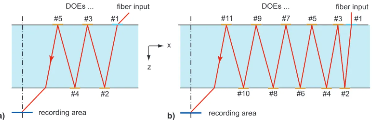
Fig. 4. Two proposed designs for the PIFSO-type collimator. The main difference lies in the orientation of the coupling fibers, in a) they are slanted, in b) they are perpendicular.
Since the number of PIFSO components in the system is not fixed, there is obviously no unique solution for the above requirements. Two possible solutions are shown in Fig. 4, which depicts corss sections of the PIFSO parts and indicates the number and the location of the individual diffractive lenses as well as the paths of the principal rays. In design a) the coupling fibers are slanted by an angle that is identical to the desired angle of incidence of the reference/address beam at the PQ:PMMA layer, whereas in design b) the fibers are perpendicular to the upper surface of the PIFSO substrate. This latter orientation has the advantage of an easier fiber alignment, however, in addition to the tasks mentioned in the last paragraph, the optical system needs to perform the necessary beam deflection between fiber ends and recording area. With this additional optical functionality, adherence to the given 1µm minimum feature size constraint requires a design
Proc. of SPIE Vol. 6992 69921C-3
PQPMMA
I
r
/\
with 11 diffractive optical elements. Essentially, these DOEs are off-axis lenses that focus and deflect the beam. Tab. 1 lists crucial geometrical and optical parameters of the designs of Fig. 4.
Table. 1. Important geometrical and optical parameters of the optical system designs of Fig. 4 (all units are µm).
DOE #1 #2 #3 #4 #5 #6 #7 #8 #9 #10 #11 position x 7865 6785 5729 4625 3545 – – – – – – diameter 200 600 774 774 500 – – – – – – focal length 4640 26359 10192 10192 –6590 – – – – – – a) excentricity 0 0 0 0 0 – – – – – – position x 8826 8732 8543 8259 7880 7405 6833 6162 5392 4520 3545 diameter 142 215 283 344 398 442 476 500 512 512 500 focal length 131053 131442 132223 133405 135005 137035 139521 142492 145983 150035 –154701 b) excentricity 4118 4131 4155 4192 4243 4307 4385 4478 4588 4715 4862
7. EXPERIMENTS
In preparation for a practical realization of the setups of Figs. 3 and 4 the fabrication process for PQ:PMMA was optimized. The best material samples were obtained using a two-step thermo-polymerization procedure that includes several dissolving, mixing, heating, and stirring steps. With custom-designed casts PQ:PMMA samples of arbitary shape can be fabricated. As one can see from Fig. 5, the material has a yellowish color, which disappears when the free PQ molecules are "consumed" by photochemical reactions during exposure. An optical characterization of the fabricated material samples yielded the C(E) curve (cumulative grating strength vs. exposure energy) depicted in Fig. 5 from which M# = 2.06 and Eτ =4.76 J/cm2 can be deduced.
0 0.5 1 1.5 2 0 2 4 6 8 10 12 Exposure Energy E (J/cm2) M# = 2.0612; Eτ = 4.7552J/cm2 Cumulative grating strength C
Fig. 5. Experimental PQ:PMMA sample and a measured curve of the cumulative grating strength vs. exposure energy.
REFERENCES
[1] P. J. van Heerden, "Theory of optical information storage in solids, " Appl. Opt. 2, 393-400 (1963). [2] D. Psaltis and F. Mok, "Holographic memories," Sci. Am. 273, 70-76 (1995).
[3] D. Sarid, B. H. Schechtman, "A roadmap for optical data storage applications", Optics & Photonics News 18, 34-37 (2007).
[4] S. H. Lin, Y.-N. Hsiao, P.-L. Chen and Ken Y. Hsu, "Doped poly(methyl methacrylate) photopolymers for holographic data storage," J. Nonlin. Opt. Phys. and Mat. 15, 239-247 (2006).
[5] M. Gruber, J. Jahns, "Planar-integrated free-space optics – from components to systems", Ch. 13 in: J. Jahns, K.-H. Brenner (Eds.), Microoptics–from technology to applications, Springer, New York (2004).
[6] M. Gruber, U. Vieth, K.-Y. Hsu, .S-H. Lin, "Design of a planar-integrated r/w-head for holographic data storage," Proc. DGaO (2007), http://www.dgao-proceedings.de/download/108/108_p47.pdf
Proc. of SPIE Vol. 6992 69921C-4