國 立 交 通 大 學
資 訊 工 程 學 系
碩 士 論 文
應用層多播線上即時串流
Application-Layer Multicast for Live streaming
指導教授:張明峰 教授
研 究 生:張雅智
應用層多播線上即時串流
Application-Layer Multicast for Live streaming
研 究 生: 張雅智 Student: Ya-Chih Chang
指導教授: 張明峰教授
Advisors: Prof. Ming-Feng Chang
國 立 交 通 大 學
資 訊 工 程 學 系
碩 士 論 文
A Thesis Submitted to
Department of Computer Science and Information Engineering
College of Electrical Engineering and Computer Science
National Chiao Tung University
in Partial Fulfillment of the Requirements
for the Degree of Master
in
Computer Science and Information Engineering
June 2006
Hsinchu, Taiwan, Republic of China
應用層多播線上即時串流
學生:張雅智 指導教授:張明峰 博士
國立交通大學資訊工程學系(研究所)碩士班
中文摘要
IP Layer Multicast 提出解決網路路由器(router)封包重複於路由之間傳送問題的 方法,使靠近客戶端的路由器可以針對特定群組而送出封包,無需經由來源端到客戶 端當中的所有路由器均參與其中。因此大量減少網路上不必要的封包傳送,使得一對 多服務變成容易許多。然而由於 IP Layer Multicast 背後的問題諸如路由器管理、缺 乏區域路由器之間多播協定、拓展能力、佈建、與異質網路結合、及對上面協定層功 能的支援如流量及擁塞控制等,因而使得至今仍未被具體實現。 目前許多研究都把重心移到應用層的多播,利用上層資料結構記錄群組成員及傳送 路徑。目前即時串流的應用程多播解決方式分為雙層架構與點對點架構。其最大的共 同點是由來源端建立起一棵傳播樹並且擔任管理的工作,在(1)指派服務節點;(2)節 點加入與離開;(3)中間節點突然遺失時傳播樹重建都需由來源端負擔。在此論文中我 們提出一些改良的方法,由每個節點記錄一些服務節點並定期更新,在加入/離開系統 及當服務節點遺失的時後由使用者自行處理,如此可減少來源端的負荷,並且將系統 負荷平均分散到使用者身上。此外,在傳播樹的建置中,我們會考慮節點到來源端間 所經過的 Hop 及數傳輸時間,使得從來源到每個節點間所經過的 Hop 數與時間都能達 到儘量最少,以便縮短傳輸延遲現象。讓每個節點擁有服務其它節點的能力,而來源 端僅需提供多媒體串流資源,故在這系統上的每個節點都有能力成為來源端而佈建自 己的傳播樹。
Live Streaming Using Application Multicast
Student: Ya-Chih Chang Advisor: Dr. Ming-Feng Chang
Department of Computer Science and Information Engineering
National Chiao Tung University
Abstract
IP layer multicast provides a solution for the problem of duplicated packets retransmission between routers, it makes only the router nearby the clients to duplicate packets to specific groups, not each router between sources and clients take part in the delivery path. Therefore, that can reduce the unnecessary packets transmission over the Internet, makes it easy for one-to-many delivery. However, many problems behind the IP layer multicast such as routers management, lack of a robust multicast routing protocol between local (inter-domain) routers, scalability, deployment, combination with heterogeneous network, and support for higher layers functionality such as flow and congestion control. As a result, IP layer multicast has not been concrete accomplished up to the present.
Today most of the research in multicast has been moved from the IP layer to the application layer, group members and delivery path are kept in the data structure in application layer. We can summarize the solution for live streaming using application layer multicast into two-tier and peer-to-peer architecture. The major common point of these are the source build a distribution tree and serve as the manager of the system in (1) assigning the service node, (2) peers joining and leaving, (3) node failure and tree reconstruction. In this thesis, we propose a refined method to diminish the burden of the source and distribute
the system load balance to the users. Each peer takes down some peer’s information when joining to the system, updating these information periodically, processing node failures. At the same time, we will consider the numbers of hops and transmission time from each peer to the source to make sure the total hops between each peer and the source is best-effort least, such that the delay can be diminished. In consequence, each peer has capability of serving, and the source just provides media stream resource such that each one has the capability to be the source and build its own distribution tree.
誌謝
首先感謝我的指導老師張明峰教授在這兩年內孜孜不倦的細心指導,讓學生得以 順利完成此篇論文。於研究所兩年求學時間裡,無論學業、觀念、生活、做人處事均 獲益良多,老師的平易近人與實驗室完善的研究環境尤使學生印象深刻,在此衷心表 達最誠摯的謝意。此外也感謝口試委員逄愛君與曹孝櫟教授於論文的建議。 特別感謝博士班孟達學長、弘鑫學長於論文中的指導與建議,芳森學長與仲雍學 長一些觀念上的釐清與實驗室同學與學弟們在這兩年來學業及生活上的幫助及鼓勵。 最後謹將此篇論文獻給我的父母給予我全心全力的鼓勵與支持,使我能順利完成 使論文。Tables of Contents
中文摘要 ...i Abstract...ii 誌謝 ...iv Chapter 1 Introduction... 1 1.1 Introductions... 1 1.2 Related works ... 2 1.2.1 Background... 21.2.2 Existing solution for streaming delivery ... 6
1.3 Motivations... 10
1.4 Objectives ... 11
1.5 Overview of this thesis ... 12
Chapter 2 Mechanism of designing P2P multicast system... 13
2.1 Overview of the proposed mechanism ... 13
2.2 Peer joins ... 15
2.2.1 Joining Peer accepted by the source/SN... 15
2.2.2 Joining Peer forwarded by the source/SN ... 16
2.2.3 Joining Peer redirected by the source/SN... 17
2.3 Distribution Delivery Tree Construction ... 19
2.3.1 Replace and dynamically adjust construction policy ... 20
2.3.2 A simulation example of peers joining ... 22
2.4 Analysis of the join criteria... 25
2.5 Process Node Leave ... 27
2.6 Different Serving Degrees ... 28
Chapter 3 System implementation... 29
3.1 Platform and Tools... 29
3.2 System implementation ... 30
3.3 Simulation Results and Demo Scenarios... 33
Chapter 4 Conclusions... 39
List of Figures
Figure 1-1 IP Multicast service model... 3
Figure 1-2 Two-tiers architecture ... 8
Figure 1-3 Multiple trees with seven nodes ... 8
Figure 1-4 Zigzag’s Single tree ... 9
Figure 1-5(a) Application layer view... 11
Figure 2-1: The source/SN accepts UA1’s request... 16
Figure 2-2 The source/SN forward the request to PeerA ... 17
Figure 2-3 The source/SN redirect with SIP 302 Move temporarily... 18
Figure 2-4 Dynamic adjustment the location ... 20
Figure 2-5 Replacement and dynamic adjustment policy ... 22
Figure 2-6 simulation of peers joining (a)(b)(c)... 23
Figure 2-6 simulation of peers joining (d)(e)(f) ... 24
Figure 2-7 Simulation input data ... 24
Figure 2-9 frame buffer issues on dynamic adjustment ... 28
Figure 3-1 CCL SIP User Agent Structure ... 29
Figure 3-2 PeerCast simulation with 100 Peers ... 34
Figure 3-3 Our method simulation with 100 peers... 34
Figure 3-4 PeerCast statistics ... 35
Figure 3-5 Our method statistics ... 35
Figure 3-6 Our method statistics with D=4 ... 36
List of Tables
Table 1-1: The difference among our solution, two-tiers and tree-based method ... 12
Table 2-1 Data Structure of peer information... 14
Table 3-1 ICMP headers ... 32
Table 3-2 comparison with PeerCast from degrees 2 to 4 ... 37
Chapter 1 Introduction
1.1 Introductions
Nowadays, Internet communications support not only traditional services, such as e-mail, chat rooms, but also new services inclusive of instant message, voice communications, video conferencing, file sharing, application sharing, white board, etc. With the mass population of emerging personal communication services (PCS) networks, multimedia streaming sharing over IP network will be a new important application. In the meantime, IP Multimedia Service (IMS) based on Session Initialization Protocol (SIP) [1] will provide more multimedia application and business. Voice/Video over Internet Protocol (VoIP) [2] has become more and more popular in recent years and undoubtedly will dominate the next generation of communication models.
IP layer multicast provides a solution for the problem of duplicated packets retransmission between routers, it makes only the router nearby the clients to duplicate packets to specific groups, not each router between the sources and clients take part in the delivery path. However, many problems behind the IP layer multicast result in high building complexity.
Many methods [3,4,5,6,7,8,9,10,11,12,13] have been proposed to use application-layer multicast to solve to the problem of broadcasting live streaming over the Internet, including client-server or peer-to-peer architecture. They are always forming a distribution delivery tree, some peers serve as a client and serving node simultaneously; however, the total delivery paths from the source to clients does not often take into account. When selecting a serving node, the closer one maybe not a
good way for the new coming node.
In this thesis, we propose a reformed mechanism for constructing the distribution delivery tree based on application-layer multicast to attain to end-to-end hops be best-effort the shortest. Every new coming node determines the best location for itself on the distribution delivery tree before joining the overlay network.
1.2 Related works
1.2.1 Background
The P2P phenomenon has radically changed the way in which everyone looks at the Internet and also aroused people’ concern in day-to-day life.
■ P2P (Peer-to-Peer)
This P2P revolution has soon reached applicative areas that were believed to be strongholds of the client-server model, such as data transmission and storage, CPU computing sharing, search engines, instant-message, massive multi-participant online world simulations, Voice/Video over IP and many other fields.
For live streaming applications, the way of media broadcasting over the networks is usually a client-server mode. In the client-server model, clients connect to server and receive directly from the server. However, it is very expensive and causes many serious problems such as bandwidth, processing power, system resource and scalability.
The P2P has some characteristics: (1) user to user, (2) either side can initiate a session, (3) equal responsibility, and in fact (4) two peers on a P2P system often require contents from third others.
■ IP multicast and Application-layer multicast
The IP Multicast service model extends the Internet delivery service for efficient multi-point packet delivery. Figure 1-1 shows the IP Multicast Service models, the concept of it was to diminish the transmission of duplicated packets over Internet routers.
Figure 1-1 IP Multicast service model
However, in spite of a decade of research on multicast protocols and applications, a globally deployed multicast service is nowhere in sight, hindered by multitudes of problems such as routers management, lack of a robust multicast routing protocol between local (inter-domain) routers, scalability, deployment, combination with heterogeneous networks, and support for high layers functionality inclusive of retransmission, flow and congestion control. Following we summarize the drawbacks of IP multicast.
First, IP Multicast requires routers to maintain per group state, which not only violates the “stateless” architectural principle of the original design, but also introduces high complexity and serious scaling constraints at the IP layer.
Second, IP Multicast is a best effort service, and attempts to conform to the traditional separation of routing and transport layers that have worked well in the unicast context. However, providing higher level features such as reliability, congestion control, flow control, and security has been shown to be more difficult than in the unicast case.
Finally, IP Multicast needs to change at the infrastructural level, and slows down the pace of deployment.
■ SIP (Session Initiation Protocol)
SIP [1] is an application-layer control (signaling) protocol for creating, modifying, and terminating sessions with one or more participants. SIP was modified from HTTP (Hypertext Transfer Protocol), had the same syntax and format with HTTP, high modifiability, defined in Request for Comments (RFC) 2543 by a working group of Internet Engineering Task Force (IETF), and a new SIP RFC 3261 has also been produced.
SIP defines five types of network entities: (1) user agent client (UAC), (2) user agent server (UAS), (3) registrar and location server, (4) redirect server, (5) proxy server. A SIP UAC can send SIP requests to UAS directly or through one or more proxy servers. Registrar and location server is used to record the addresses mapping of each SIP users queried by proxy or redirect servers. When receiving a SIP request, a redirect server responds a caller’s SIP request with the callee’s real location (in the form of SIP URL). In this thesis, we will combine the (1), (2), and (4) into a SIP UA, and a relay server is also included.
SIP uses SDP [14] in an answer/offer mode. A caller sends an INVITE with an SDP description that describes the set of media formats, address, and ports (for different media sessions) that the caller is willing to use. This set of media formats comprises an offer by the calling party. The called party responds with an SDP description that aligns with the offered SDP description, but which includes an acceptance or rejection of each of the offered media formats. The result of this exchange is an agreement between the two parties as to the types of media they are willing to share.
SDP is specified in RFC 2327 entitled “SDP: Session Description Protocol”. Nowadays, a number of modifications to the protocol have been suggested such as RFC 3266 entitled “Supporting for IPv6 in Session Description Protocol (SDP)” obsoletes RFC 2327 by supporting IPv6, RFC 3264 entitled “An Offer/Answer Model with Session Description Protocol (SDP)” updates RFC 2543 with an Offer/Answer model.
SDP simply provides a format for describing session information to potential session participants. Basically, a session is comprised of a number of media streams (voice/video/text/application…). Therefore, the description of a session involves the specification of a number of parameters related to each of the media streams. Parameters are divided into two parties: session-level parameters and media-level parameters. Session-level parameters include information such as the name of the session, the originator of the session, and the time(s) that the session is to be active. Media-level parameters include the media type, port number, transport protocol, and media format.
Because SDP simply provides session descriptions and does not provide a means for transporting or advertising the sessions to potential participants, it must be used in conjunction with other protocols (such as SIP). For example, SIP carries SDP
information within the SIP message body.
Similar to SIP, SDP is a text-based protocol, utilizing the ISO 10646 character set in Unicode Standard Transmission Format (UTF)-8 encoding (RFC 2044). SDP field names use only US-ASCII, and textual information may be passed in any language. Although the use of ASCII coding in SDP, as opposed to binary coding, is a little bandwidth greedy, SDP is written in a compact from to counteract bandwidth inefficiency.
1.2.2 Existing solution for streaming delivery
There are various solutions for streaming delivery using application-layer multicast. Some of them need a powerful streaming server to deliver the streams to each client, and these systems are usually provided by ISPs (Internet Service providers) or companies for charging.
The others do not use external servers but deliver the streaming by the user participating in the overlay network. The streaming source node handles most of the operations, including building the distribution delivery tree, forwarding each new coming client to an appropriate serving node, rebuilding the connections of some nodes in case of a serving node leaving, crash or failure due to software or hardware problems. Each function of these takes little times and may influence the quality of the system.
The method of live streaming delivery using application-layer multicast can be categorize into four classes. Following shows a representative work for each one that we have surveyed.
two-tiers. It use ISP’s proxy servers serve as the media servers to establish distribution delivery trees using the low layer routing algorithm built between every server’s routing table. It is expensive and these well-known proxy servers maybe easy to under attack.
(2) PeerCast [12, 13, 20]: a P2P architecture without any streaming server. The source handles the tree construction while peers joining, and tree reconstruction while peers leaves or failures. SN selection policy is based on random or locality policy by peer’s redirection. However, the policy may choose a SN with long distance between, even if finding a SN with very small hops between, it might still not guarantee the total delivery paths between the new coming node and the source are short. Currently, PeerCast is open-source and free to use.
(3) SplitStream [4]: A tree-based architecture but splits the streaming to N parties (strips called in the thesis), each part was delivered over one tree. Every node takes its role as a serving node in one tree, and a leaf node in the other N-1 trees. Each peer gives back to the network as much as bandwidth as it consumes, it is designed to overcome the unbalance forwarding load in single tree architecture. This method is used to reduce the influence of the node failures. The failure of any single node can only lead to the interruption of one tree over the architecture. However, the tree construction is complex and needs a streaming description method such as MDC (Multiple Description Coding) to identify each streaming part. Delay of each tree is not stable for real-time application. Figure 1-3 shows an example of multiple trees with seven nodes in logical view.
Figure 1-2 Two-tiers architecture
Figure 1-3 Multiple trees with seven nodes
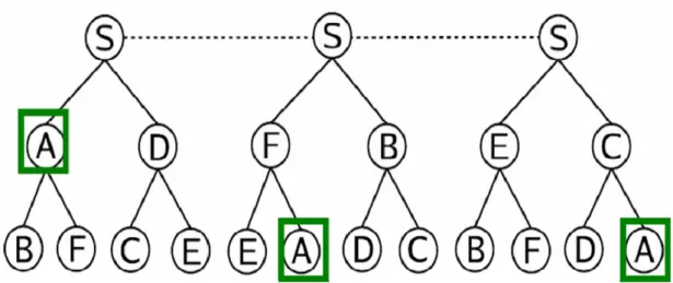
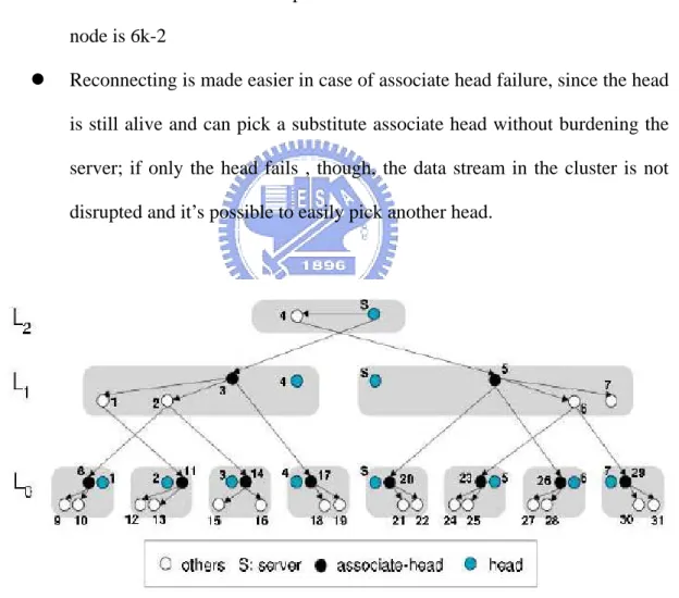
(4) Improved Single-tree Approaches: Most of the Single-trees method are managed by the root, and they are good at delay, but sill have problems on the nodes leaves of failures. Zigzag [21] is a proposal from the University of Central Florida which addresses robustness problem of the single-tree architecture by splitting the role of the leader over two different entities, the head and the associate-head. Heads inherit all the administrative functions of the leader, except the responsibility of forwarding the data stream to others. Associate heads are picked between the non head peers of a
cluster and are delegated both the privilege to receive data from the higher layer and relay streams to their cluster-mates. In addition, all non-head peers of a cluster in a higher level can forward the streams to the associate-heads on the lower-level clusters. Once their associate-head fails, the children can contact to their cluster head. Figure 1-4 illustrate the tree proposed on Zigzag. The improvements brought by these changes are the following (k is a constant value, k>3):
z Any peer cannot directly serve more than 6k-3 peers
z The worst-case number of peers that need to reconnect due to a crashed node is 6k-2
z Reconnecting is made easier in case of associate head failure, since the head is still alive and can pick a substitute associate head without burdening the server; if only the head fails , though, the data stream in the cluster is not disrupted and it’s possible to easily pick another head.
Figure 1-4 Zigzag’s Single tree
Multiple-source technology used in file-sharing environment may not appropriate for streaming multicasting. The drawback of multiple-source method are
(1) needs exchange massive messages for query the frames that the user lack of, (2) needs a method to avoid receiving the duplicated packets, (3) delay is not steady thus can not assure of real-time transmissions.
In this thesis we do not use mechanism similar to distributed hash table (DHT) such as Chord, or Content-Addressable Network (CAN) which are mostly used in recently peer-to-peer architecture. In the DHT method, most of these nodes in the tables do not actually request the content of the media from the source, but they have to relay the content for some nodes (once the software is executed and online, they are constructed into the DHT), this result in fairness problem. Another problem is that because our streaming data is transfer on single connection (for the infinity length streaming feature, it is not easy to index like a fix-length media file and obtain from multiple source), DHT is not appropriate for this need.
1.3 Motivations
Currently, multimedia streaming sharing always needs media servers. The burden on media servers get increased with more and more clients connections. On the other hand, most of these media servers are always well-known; they may be vulnerable to DoS attacks. Most importantly, the network capability does not increase with the numbers of connected clients but is constant and bounded, and requires the manual addition of the servers to be increased.
At the same time, P2P architecture does not use broadcasting methods, every peer receiving data streaming from others also contributes resources to others, and any peer may not be impacted on others leaves or crashes.
with the actual one from the IP layer. When constructing a delivery tree, the delay is proportioned to the hops between. Defining the cost function of the tree be the sum of the routing path of each peer to the source, hence, our goal in this thesis is to form a shortest path delivery tree.
Figure 1-5(a) shows the view on the application layer, streaming direction is from peer A to B, and peer B to C. However, the real topology could be the case in figure 1-5(b), that is to say, C is far from peer A. The latency will be reduced if the streaming is directly from peer A to C as shown in figure 1-5(c). At the meantime, for C, the numbers of routers to A and B are the same but A is the better choice due to it is nearby the source than B if we consider the total routing path from the source.
A
B
C
A
B
C
R1Figure 1-5(a) Application layer view Figure 1-5(b) IP layer view
A
B
C
R1
Figure 1-5(c) the best path
The purpose of this thesis is to design a multicast system for live video/audio streaming sharing, it is a distribution delivery tree architecture, peers in this system perform most of operations by themselves. Using peer list, we can diminish the burden of the media source when (1) joining or leaving the system; (2) SN selection; (3) recovering from SN leaves or failures.
In our implementation, SIP is used as the signaling protocol and RTP [15] (Real-Time Transport Protocol)/RTCP [16] (Real-Time Control Protocol) are used to deliver the media streaming on Internet.
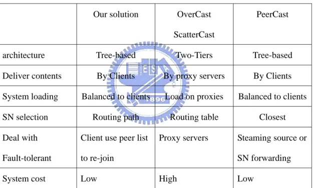
Our solution OverCast
ScatterCast
PeerCast
architecture Tree-based Two-Tiers Tree-based
Deliver contents By Clients By proxy servers By Clients
System loading Balanced to clients Load on proxies Balanced to clients
SN selection Routing path Routing table Closest
Deal with Fault-tolerant
Client use peer list to re-join
Proxy servers Steaming source or SN forwarding
System cost Low High Low
Table 1-1: The difference among our solution, two-tiers and tree-based method
1.5 Overview of this thesis
The remaining of thesis is organized as follows. Chapter 2 describes the concept of the live streaming multicast system. Chapter 3 presents the architecture and system implementation. Conclusions and future work are given in Chapter 4.
Chapter 2 Mechanism of designing P2P
multicast system
2.1 Overview of the proposed mechanism
The chief purpose of the proposed mechanism is to construct a shortest path distribution delivery tree for media streaming sharing under peer-to-peer environment. There are three principles in this thesis: (1) balance the loading of the media source; (2) find and contact a nearby SN that has shortest routing paths from the media source to clients; and (3) dynamic adjustment the location for each peer. When a new coming node wants to join this system, it first contacts the source, the major task of the source is to determine whether directly accepts this request or responds with a redirection message that contains some SNs’ information so that the new coming node can determine by itself which to contact using a simple measurement method in its peer layer.
Define the data structure of each peer in the peer list and the function of each member variable. Each UA maintains one peer list that contains partial peers’ information which it knows about on the overlay network. Table 2-1 shows the data structure of each peer’s elementary information, and a peer list is composed of one to many peers. Most of the peer information can be obtained by one pass; each peer maintains two global variables for itself, “g_Hops2Source” and “g_RTT2Source”, which are obtained by two passes. Each peer can designate different serving degrees in terms of its capabilities such as processing power, network bandwidth, system loading, memory resource, resource usage, etc.
Table 2-1 Data Structure of peer information
We keep this data structure as simple as possible; therefore, we can include some information within the SIP request/response message by adding them as a header parameter and need not change the original SIP syntax. In our implementation, two header parameters are included in the SIP “Contact:” header, r stands for RTT to “the source” and h stands for numbers of hops to “the source”.
The functions of each peer include (1) sending a SIP message to the media source or SN, (2) detecting a SN, (3) exchanging peer list with others for update periodically, (4) relaying media streaming for other peers, (5) recovering from node failure by peer list, and (6) dynamic adjustment. The media source just provides streaming media to the system, it does not keep the global states of the overlay network and manage nothing. We want to make the media source as if resembling any other peer.
2.2 Peer joins
First, we define an entity: SN, a super node or serving node, is a SIP UA that can relay the signaling and streaming media from the media source to the requester. Every peer in this overlay network has the ability to become a SN in terms of their capabilities such as processing power or network bandwidth, etc.
When a SIP UA wants to receive the streaming media, it has to first contact the media source or to obtain a peer list. The media source receives the request message and determines in terms of its capabilities whether to accept this request or respond with a peer list to ask the new coming peer choosing another peer as its SN. If the selected SN has enough capacities, it will accept this call, otherwise, it sends a response with children peers’ information from its peer list to the new coming peer, and these steps are continuous until the new coming peer finds one SN with the shortest routing path through it.
We use SIP for our signaling control and combine some behavior of SIP servers (e.g., redirect server and relay server) into the original SIP UA. Our join algorithm is almost implemented and accomplished on the “Peer layer”.
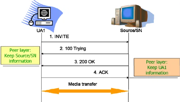
2.2.1 Joining Peer accepted by the source/SN
Figure 2-1 illustrates the signaling flow when the media source/SN accepts UA1’s request in terms of its capabilities. Both the new coming peer UA1 and the source/SN should run a ping echo routine to obtain the numbers of hops and RTT between each other and record this information into the peer list. Using the peer information one can know how far the routing path to the source of each peer.
Figure 2-1: The source/SN accepts UA1’s request
After receiving the SIP ACK message, the source/SN joins UA1 to its RTP streaming member list. Then the new coming peer UA1 can obtain media streaming from the source/SN.
2.2.2 Joining Peer forwarded by the source/SN
If the source/SN has up to its capabilities or maximum serving degrees, it can forward this request message to another peer which is selected by random policy, round-robin policy, or locality policy. Figure 2-2 shows the signaling flow of this method.
There are various policy in common use proposed by [16], (1) Random policy: the source/SN randomly chooses a peer from its peer list; (2) Round-Robin (RR) policy: the source/SN chooses a peer with maximum surplus serving degrees, each node requires some state information of others; (3) Smart-placement policy: the
source/SN chooses a closest node; (4) Knock-downs policy: If the requesting node is closer to the source/SN node ( or in terms of network bandwidth), the source/SN node will accept the requesting node as its child, and redirect the farthest node.
Figure 2-2 The source/SN forward the request to PeerA
This method can be used in case of UA1 is not powerful to become a SN (this can be accomplished by adding another parameter in the SIP header to describe joining peer’s serving degrees). We may want this kind of peer to be a leaf in the overlay network because it cannot serve anymore. Therefore, the source/SN can select a peer with the longest path to the source and forward to it. In next section, we will describe how to select the best SN for each peer that can also become SN in the overlay network.
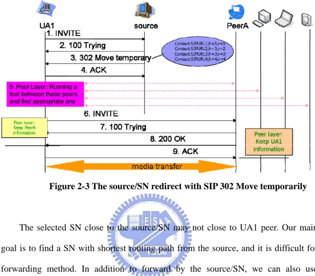
Figure 2-3 The source/SN redirect with SIP 302 Move temporarily
The selected SN close to the source/SN may not close to UA1 peer. Our main goal is to find a SN with shortest routing path from the source, and it is difficult for forwarding method. In addition to forward by the source/SN, we can also use redirection mechanism.
Figure 2-3 shows the signaling flows when the source/SN rejects the INVITE request from UA1 and sends a redirect response message with the peer information. The 302 Moved temporarily message is used to tell UA1 that the source/SN cannot accept this request in terms of its capabilities and provides its children peers to UA1 for choosing. The reasons for only sends children peer are that the source/SN presumes UA1 already knows about some peers and from these peers UA1 can choose a best one from them. These children peers’ information are packeted into the SIP 302 Moved_Temporarily response message in the form as illustrated in Figure 2-3:
At the peer layer, UA1 parses the message and extracts peers’ information from the response message, stores to peer list; it also executes an ICMP echo routine iteratively and compares with the peers already in its peer list to find a SN with shortest path to the source. With the ICMP echo function, if the remote peers are reachable they will copy the original data packets to a serious of reply packets and send them back to the echo requesting node.
When receiving these replies packets, we calculate the round-trip time (RTT) by the difference from the first sending packet to latest receiving one and numbers of hops between. Every computer implements the ICMP echo function, so we can use this to measure the network state. Therefore, we can choose the peers with lowest hops between and lowest transmission time to contact. Because we have known the numbers of hops between the selectable serving peers and the source from the SIP 302 response message, store them to each “Hops2Source” of specific peer data structure, after ICMP echo function we can obtain the “Hops2Peer” information of each. Adding “Hops2Source” and “Hops2Peer” of each peer and selecting the minimum one. If the selected SN accepts this request, setting UA1’s global variable with them.
(1) g_Hops2Source = SN.Hops2Source + SN.Hops2Peer + 1; (2) g_RTT2Source = SN.RTT2Source + SN.RTT2Peer + 1
In next section, we will describe our algorithm in more detail by using a simulation example.
2.3 Distribution Delivery Tree Construction
application layer that maintains the stateless nature of the network. In addition, we believe that the solutions for supporting higher layer features such as error detection and correction, flow and congestion control can be significantly simplified by leveraging well understood unicast solutions for these problems.
2.3.1 Replace and dynamically adjust construction policy
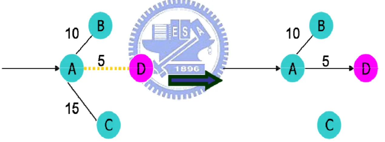
When every new coming node joins, the location of peers in the overlay network will dynamically adjust to response our shortest path finding mechanism. Figure 2-4 shows the concept of dynamic adjustment on each serving node.
Figure 2-4 Dynamic adjustment the location
In figure 2-4, the SN A originally has two children node B and C, if A’s maximum serving degrees are two, a new coming node D has shorter routing path than B and C, SN A therefore selects D as its child and replaces C (C is longer than B in routing path). C will re-join the overlay network and this dynamic adjustment happen recursively to C’s children simultaneously.
Figure 2-5 shows an example of three new coming peers {A, B, C} that want to join the overlay network created by the source. From the views on the application
layer, if the joining sequence is A, C, and B, figure 2-5 (a) shows the delivery tree where B can select one of {A, C} as its SN by only the transmission time due to the numbers of hops between AB are equal to that between AC, and we assume B chooses A.
On the views on the IP layer shown in figure 2-5 (c) we can calculate the routing path from the source to A and C are 27 but from the source to B is 54. Define the cost of the overlay tree are the sum of routing path from the source to each peer, we can calculate the cost are 27+54+27=108. With dynamic reconstruction policy shown in figure 2-5 (b), when peer B joining, the source finds B is closer than A or C, thus it knocks down one of {A, C} with the longer transmission time and chooses B as its new child, and we assume B replaces A. The replaced peer A recalculates the distance of “source-B-A” and “source-C-A” and selects B or C as its new SN, in this case they are the same so A can use the transmission time for choosing.
Now, the routing path from the source to B is 2 and 29 to A, the cost of the tree are 2+29+27=58. If letter a new coming node selects B as its SN, the routing path can be better than the former case as shown in figure 2-5 (a).
Figure 2-5 Replacement and dynamic adjustment policy
2.3.2 A simulation example of peers joining
We develop a simulation tool to illustrate the tree construction step by step. First we randomly generate a square array with size n by n as input data, n stands for the peers participated in the system, and assume each node has the same maximum serving degrees of 3. In practice, the maximum serving degrees of each node can be different in terms of their capabilities.
The joining criteria we take here is the routing path from the source to each node, assuming the transmission time (or RTT) between two peers are proportions to the numbers of hops between; therefore, our simulation is only focus on the latter metric.
Figure 2-6 (a) shows the result of P1, P2, and P3 joining. After accepting three connection requests, P0 has up to its maximum serving degrees. In reception of request message from P4, P0 determines P4 is closer than P1, therefore, P0 chooses P4 as its new child to replace P1. At the same time, P0 provides its children {P2, P3, P4} to P1 and P4 provides its peer list information {NULL} (NULL in this case) to P1, then P1 combines these information and knows about there are three selectable peers {P2, P3, P4} and how they are far from the source P0. The replaced node P1 determines a new appropriate SN by calculating “Hops2Source + Hops2Peer” as describe in figure 2-6 (b). The result is showed in figure 2-6 (c). In practice, the SNs are needed to be calculated in the routing path, thus the g_Hops2Source variable need to add 1 for each SN in our implementation and simulation.
Figure 2-6 (d) shows the case of P5 joining and replaces P2, using the same algorithm P2 has selectable peers {P3, P4, P5} and eventually P3 is selected as illustrated in figure 2-6 (e). When P6 joining, no peer is farther from P0 than P6, thus P0 redirects it to its children {P3, P4, P5} and P5 is selected as figure 2-6 (f) shows.
Figure 2-6 simulation of peers joining (d)(e)(f)
If the replaced peer has children, it should notify all its children of dynamically adjusting because of there are some other peers better than its parents. If the children also have children, they will be notified recursively until the lowest level.
Up to present, by the policy of replacing the farthest peer with a close one on the routing path. The routing path from the source can be reduced level by level and the total routing path is taken into account. Figure 2-7 is our simulation input data, a square array, every element with a index [row][column], or A[i][j] for short, presents the numbers of hops between peer I and peer J, thus A[i][j] = A[j][i] and A[i][i] = 0. Other A[i][j] maybe zero if they are under the same subnet. We do not consider the reach less problem on the network states, therefore A[i][j] cannot be negative.
Without dynamic adjustment and replacement policy, the latter coming peer will
always on the leaves layer and have no chance to find a better SN except rejoining the overlay network.
2.4 Analysis of the join criteria
At the beginning the replacement may happen frequently, the numbers of impacted nodes due to recursively replacing are very small. With more and more nodes joining the overlay network, the upper links especially those close to the source are hardly to be replaced, thus the impacted nodes are limited to a range of specific levels. If D is the maximum serving degrees of the tree, the replaced node is at level I, and the tree has a level L. Total impacted node are less than
1 -D ) 1 (DL−I+1 − , more I approach to L, smaller 1 -D ) 1
(DL−I+1 − is. The shape of the spanning tree is
depended on the network topology.
We also concern about the time complexity of one new coming peer joining. If N represents the numbers of peers on the overlay network, D represents the maximum serving degrees of each peer, and peers reaches to its maximum serving degrees are called saturated peers (or SP). When the new coming peer contacts any saturated peer, it will be redirected to others or replace one child of the saturated peer. First we want to know how many saturated peers are on the system. If I represents the maximum level over it all the peers are saturated, thenD0 +D1 +D2 +...Di<N.
⎣
⎦
⎣
( 1) 1⎦
1 1 ) 1 ( 1 1 ) 1 ( 1 1 -D D D 1 1 − + − < ⇒ + − < + ⇒ + − < ⇒ < − + + N D i N D i N D D N D D i i ㏒ ㏒ ㏒There are ⎣ ⎦ ⎣ ⎦ 1 1 1 1 ...D D D D 1 ) 1 ( 1 1 ) 1 ( 1 -i 2 1 0 D D − − ≅ − − = + + + − + − − − D D D D ㏒ D N ㏒ D N < SP < ⎥⎦ ⎥ ⎢⎣ ⎢ D N
on the system. We can then define the joining cost of each peer in the form of:
% 100 ) ( % 100 % 100 1 1 1 × Δ = × − = × Δ =
∑
− = − nodes t SP nodes RC RC nodes st redirectCo n t i i i JoinCostThe ΔSP(t) stands for the difference redirection cost between RCi and RCi-1
after peer i joining. RCi stands for the total redirection count over the system after
node i join. The departing cost of peer i has the same definition with the joining cost because one peer departing may increase the redirection cost of the system. A redirection cost is similar to an accepting cost because of they represent a transaction element in SIP. Hence, we take the redirection cost into account, not only the replaced peers in calculating joining cost. The larger serving degrees each peer has, the smaller saturated peers are on the system, and thus the joining cost can be reduced obviously in our simulation result. In practice, each new coming peer may not contact to all the saturated peers.
We use a best-effort method for finding a shortest routing path from the source. In the best situations, peers on the lower levels need to frequently determine whether a better SN exists or not whenever a new coming peer joins. But it is difficult for a P2P overlay network to know about someone’s joining without a global state maintainer. Therefore, we fire up a timer counter on each peer for dynamically adjusting, whenever the timer is triggered, peers can exchange the peers’ information with others and run the chooseSN() routine for determining the existence of another better SN. More far from peers to the source, more frequently the dynamic adjustment happen. There are two situations the dynamic adjustment should happen: (1) timer trigger, (2) parent or upper level peers have been replaced or left.
2.5 Process Node Leave
When one peer leaves, all of its children need to reconstruction for receiving streaming media continuously. In normal situations, each peer which wants to leave the overlay network must send a SIP BYE request to its immediate parent and children. When the parent node receives a BYE request, it just deletes this peer information from its peer list and removes the peer record from the RTP member list to stop transferring streaming media. On the other hand, when children receive a BYE request from its SN, they first choose a new SN respectively and rejoin to the overlay network. Afterwards, they should notify their children of this reconstruction and this is recursively until the leaves nodes complete reconstructions. This reconstruction is accomplished recursively to avoid massive peers simultaneously rejoining.
A node usually dynamically adjusts only when its SN has been replaced, timer triggered or SN leaves. In general, there will be many nodes joining or leaving unknown by other peers as time goes on. Thus the exchange of peers’ information and SN determination are accomplished by the timer counter.
It is necessary to take frame buffer [17] into account when dynamic adjustment from one SN to another. Figure 2-9 shows the frame buffer issues on dynamic adjustment. When P4 joining, assume P4 replaces other peer and receives packets from frame 31. Afterward, we also assume P3 determines P4 is a better SN after triggering of timer, receiving the first from P4 is frame 31, but it has received to 20 at the current time. Therefore, P3 needs to wait for receiving frames 21 to 30 from P2 then send SIP BYE request to P2. The buffer manager on low layer will rearrange the order of the frames to play.
Figure 2-9 frame buffer issues on dynamic adjustment
2.6 Different Serving Degrees
On the normal Internet network situations, peers may have different serving degrees. After tree construction, there may be peers with little degrees on top of the tree and peers with larger degrees on the bottom of the tree. If promoting the peers with larger degrees up to top levels could go down the cost of the tree, we can promote them up.
Having a bonus point mechanism, we can let the peers with degrees get bonus periodically and promote them up when getting the specific point. For example, peers with degree 1 can get 1 bonus and 2 bonuses with degrees 2.
Peers could rejoin the system when they reach the specific point, with this improvement the source/SN determines whether to replace the children not only by the hops or RTT between, but also by their bonus point, the decisive factor of each metric may be 50%. Eventually, the peer with little or zero serving degrees will be moved down to the low levels.
Chapter 3 System implementation
3.1 Platform and Tools
■ Hardware and Software
We use Microsoft Visual C++ 6.0 integrated development environment (IDE) tools to implement on CCL SIP User Agent (UA). The CCL SIP UA [18,19] was implemented by the Computer & Communication Research Laboratories (CCL) of the Industrial Technology Research Institute (ITRI). Execution file and simulation tool run on Microsoft Windows XP operation system.
■ Protocol stack of SIP UA
CallManager MediaManager UAProfile UI UACore cclRTP Codec WaveIO sipTx RTP SIP SDP Transport Peer List
Figure 3-1 CCL SIP User Agent Structure
user’s command, settings and invoke the “CallManager” layer. The “UAProfile” layer is used to save all user configurations including local address, proxy, registrar, SIP user name, and host name…etc. The “PeerList” layer keeps the remote selectable serving nodes’ information such as IP address, Port number, user name, RTT to the media source, and numbers of hops to the media source…etc. The “CallManager” layer implements the SIP dialog behavior and core call control models by providing the “UACore” callback functions, and it also refer to the “MediaManager” layer to control and process media session objects. The “UACore” layer is designed for UA kernel, used to create SIP message objects, SDP object contained in SIP message and control the creation and deletion of SIP dialog objects. The “SipTx” layer is a single thread event-callback programming model, and serves as the finite state machine (FSM) of SIP UA by implementing the four types of SIP transactions defined in RFC 3261. The “SIP” layer implements all functions of SIP such as create SIP request and response messages and modify header contents. The “Transport” layer is responsible for low-layer network APIs, including socket management, network initiation…etc. The “MediaManager” layer refers to the “WaveIO” layer for media playback, recording and refers to the “cclRTP” layer for RTP handling.
3.2 System implementation
We implement first on SIP UA for accepting multiple calls by modifying RTP member list receiver. Using the cclRTPAddReceiver() routine in the “MediaManager” layer to open a new RTP session and add a new client to the RTP member list in the “RTP” layer, all actions are accomplished in the “MediaManager” layer. The cclRTPSetEventHandler() routine in the “cclRTP” layer creates a new thread for reading received RTP packets and callbacks to the routine RTPEventHandler() for
writing the received RTP packet to a “Read Buffer”. Another thread triggers the corresponding callback routine CMediaManager::RTP2Wav() to read data from the “Read Buffer” and then calls the WavInOut::wavOutOpen() routine for playing the streaming data.
Then we implement the function of redirect server for supporting creation and processing of the SIP 302 Moved_Temporarily response. When the UAS receive a SIP INVITE request, if its serving degrees are not full, accepts this call and opens RTP session directly; otherwise, creates a SIP 302 Moved_Temporarily response with the “Contact:” header filled in its children peer information, and waits for the SIP ACK message for deleting this dialog session. On the other hand, when the new coming node receives the SIP 302 Moved_Temporarily response on the “Transport” layer, the peer information in the “Contact:” header will be handled in the upper two layer: “UACore” and “CallManager”. In the “UACore” first parses the information of the “Contact:” header and passes it to the “CallManager” layer for parsing and recording peer information to peer list data structure, then uses ChooseSN() routine to select an appropriate SN and return to the “UACore” layer.
The “UACore” layer uses the original SIP request message and the selected SN to create a new SIP INVITE request, transaction, adds to the original dialog, deletes the original transaction from the dialog, sets the dialog state to “Dialing”, and passes to the “SipTx” layer to send this new SIP request to the new serving node. At the same time, the client also sends a SIP ACK message to the previous serving node to response the receiving of SIP 302 Moved_Temporarily redirect message.
Every SIP UA also needs to implement the function of relay servers. Media streaming packets on the “Transport” layer will pass to the “RTP” layer thread in terms of the packet port number (this is accomplished within the event-driven call back programming model in one Dispatch thread). When the “RTP” layer receiving
these streaming packets, it will lookup the member list of the same RTP session, and relay these packets it has received from its serving node to all children in terms of the information on RTP member list.
The “Peer List” layer implements the Internet Control Message Protocol (ICMP) functions, which is used to help the IP layer for error control, for example, when a datagram cannot reach its destination, the ICMP messages can typically report errors in the processing of datagram. In this thesis we use the echo function of ICMP to obtain the TTL and RTT. In fact, ICMP can detect many error functions with different message format. Table 3-1 shows the data structure of ICMP header used for Echo functions defined in RFC 792.
Field Descriptions Type Define the type of this message, such as ECHO request(8) or reply(0)
Code Harmony with Type to specify the reason of the error CheckSum Verify the correctness of the request data
ID If Code=0, an ID to aid in matching echoes and replies, may be zero Sequence Same with ID in currently define
Table 3-1 ICMP headers
Our ECHOREQUEST data structure hence include an ICMP header and dwTime, used to record the time of when this request is sent, a serious of data. When receiving the ECHO reply message corresponding to the sequence number of packet we have just sent, calculate the received time and minus the sending time (dwTime in the ECHO reply message), that is round-trip time (RTT).
1500 bytes, and IP header is 20 bytes) to reduce the transfer number of packets.
3.3 Simulation Results and Demo Scenarios
■ Simulation Results
We write a simulator program to simulate the distribution delivery tree when there are many nodes join the system. Figure 3-2 shows the simulation of PeerCast with 100 peers and figure 3-3 shows the simulation of our method with 100 peers. From the comparison with PeerCast in simulations, we can reduce the “Tree Cost” and “Join Cost” at the same time.
In figure 3-2 the maximum level of the tree is 6 and the level 4 is not full, but in figure 3-3 the maximum level of the tree is 5 and the level 4 is almost full and better in the “Tree Cost” and “Join Cost”. Because we take the routing path from the source to each peer into account, we can have a better cost than PeerCast. When selecting a SN, PeerCast always choose the closest one, hence this results in many replacement happen and reflects on the “Join Cost”.
Figure 3-2 PeerCast simulation with 100 Peers
Figure 3-3 Our method simulation with 100 peers
Figure 3-4 and 3-5 illustrate the statistics of the result with 100 peers from figure 3-2 and 3-3. In figure 3-4 there are 4 peers on the system on the system with the JoinCosti over 40%, but in figure 3-5 that are 3 peers. The “Tree Cost” is 78 saved and
Figure 3-4 PeerCast statistics
Figure 3-5 Our method statistics
Peers with more degrees can help the system reduced the “Tree Cost” and “Join Cost” because of the (1) routing path, (2) replacement and (3) redirection are reduced. Figure 3-6 and 3-7 shows the statistics when peers with serving degrees 4 and 5 respectively, here we assume every peer has the same serving degree.
In figure 3-6 there is only one peer with Join Cost over 40%, the “Tree Cost” is 87 saved and the “Join Cost” is 188 saved than figure 3-5 in total. In figure 3-7 the “Join Cost” of each peer is less than 20%, the “Tree Cost” is 129 saved and the “Join Cost” is 325 saved than figure 3-5.
Figure 3-6 Our method statistics with D=4
Figure 3-7 Our method statistics with D=5
Table 3-2 shows the comparison with PeerCast in the same input data with the degrees from 2 to 4. Obviously, the join cost will reduce gracefully while the serving degrees increasing. Table 3-3 shows our simulation result when the serving degree increased from 2 to 7, the variation on the tree cost and redirection cost of the system. Especially, the join cost of each peer is no more than 10% while the serving degree is up to 7.
Table 3-2 comparison with PeerCast from degrees 2 to 4
Table 3-3 variations with different serving degree
■ Demo Scenario
We describe our demo scenario as follows:
(1) Scenario 1: 1-to-many call, UA0 serve as the media source, UA1 and UA2 send SIP INVITE request to UA0, then UA0 can talk to UA1 and UA2.
(2) Scenario 2: redirect, select SN, and media relay. Follow the example above, there is a new coming peer UA3, UA3 was rejected and redirected by UA0. UA3 use
the peer information contain in SIP 302 redirect message and call the ChooseSN() routine to find an appropriate SN. In the meantime, the SN accepts the call and open media relay function.
(3) Scenario 3: self reconnection, when UA3’s SN leaves the system, UA3 run the ChooseSN() routine to rejoin the overlay network, at this time, UA0 is the best SN.
Chapter 4 Conclusions
Multimedia and streaming sharing will bring an extreme fanaticism in recent years, and especially apply to multicast application environment such as personal TV show, personal radio station, etc. Although this can easily be accomplished by using client-server models, but the building cost is very expensive in servers’ maintenances for service providers or companies. From the point of view of most users, they may want to save money, and peer-to-peer architecture provides a good solution for this in another robust way. The most fascination of using peer-to-peer architecture is that all services are free of charge, and the quality of service (QoS) impends over the client-server model can come true in a few days.
In this thesis, we construct an overlay distribution delivery tree for live streaming multicast. When selecting one appropriate serving node, not only consider the distance between the new coming node and the serving node, but also calculate the total distance from the media source to this new coming node through the serving node. The total distance between the new coming node and the media source can be obtained in two passes. In the first pass, the new coming node can receive from some selectable serving nodes the information about how far they are from the source, and in the second pass, the new coming node calculates the numbers of hops and round-trip time between each selectable serving node by itself. From these two passes, the new coming node can sum up the information and send SIP INVITE request message to the selected serving node by choosing one with least hops or RTT between. This step is continuous until the new coming node finds a serving node that can accept the request.
For the client-server model, the system capability in term of the media servers, when the numbers of clients increase, the only way to serve the clients is to increase
the number and capability of the servers simultaneously for keeping the service qualities. Using peer-to-peer architecture, each peer serves as a client as well as a serving node at the same time, more nodes on the overlay network, more capabilities the system has. Since all clients upload contents when playing media, everyone becomes a server (or broadcaster) like the traditional media servers. Load balance and self organization are accomplished in P2P architecture.
In the future work, we will consider the bandwidth of each peer to determine its appropriate serving degrees. Because we know every peer on the Internet has different capacities, such as processing power, bandwidth, and system resources. These situations result in the different serving degrees on each node. At the same time, we may also want to let the peer with more capabilities closer to the media source to serve more nodes to reduce the transmission delay.
Reference
[1] J. Rosenberg, H. Schulzrinne, G. Camarillo, A. Johnston, J. Peterson, R. Sparks, M. Handley, E. Schooler, “SIP: Session Initiation Protocol”, RFC 3261, June 2002.
[2] Daniel Collins, Carrier Grade Voice over IP, McGraw-Hill, New York, 2001. [3] Venkata N., Padmanabhan, Helen J. Wang, Philip A. Chou, “Resilient Peer-to-Peer Streaming”, Microsoft Research, 2003.
[4] Miguel Castro, Peter Druschel, Anne-Marie Kermarrec, Animesh Nandi, Antony Rowstron, Atul Singh, “SplitStream: High-Bandwidth Multicast in Cooperative Environments”, Microsoft Research, 7 J J Thomson Avenue, Cambridge, CB3 OFB, UK. Rice University, 6100 Main Street, MS-132, Houston, TX 77005, USA, 2003. [5] Vinay Pai, Kapil Kumar, Karthik Tamilmani, Vinay Sambamurthy, Alexander E. Mohr, “Chainsaw: Eliminating Trees from Overlay Multicast”, Department of Computer Science Stony Brook University, 2004.
[6] Xinyan Zhang, Jiangchuan Liu, Bo Li, Tak-Shing Peter Yum, “CoolStreaming/DONet: A Data-Driven Overlay Network for Efficient Live Media Streaming”, The Chinese University of Hong Kong, Simon Fraser University, Vancouver, BC, Canada, 2004.
[7] Xuxian Jiang, Yu Dong, Dongyan Xu, Bharat Bhargava, “GNUSTREAM: A P2P MEDIA STREAMING PROTOTYPE”, Department of Computer Sciences, 2003 [8] Jin Li, “PeerStreaming: A Practical Receiver-Driven Peer-to-Peer Media Streaming System, One Microsoft way, Bld, 2003”
[9] Y. Chu, S. Rao, and H. Zhang, “A case for end system multicast”, in Measurement and Modeling of Computer Systems, 2000
[10] Yatin Chawathe, Steven McCanne, Eric Brewer, “An Architecture for Internet Content Distribution as an Infrastructure Service”, 2000.
[11] John Jannotti, David K. Gifford, Kirk L. Johnson, M. Frans Kaashoek, James W. O’Toole, Jr, “Overcast: Reliable Multicasting with an Overlay Network”, Cisco Systems, 2000.
[12] H. Deshpande, M. Bawa, and H. Garcia-Molina. "Streaming Live Media over a Peer-to-Peer Network", Technical Report, Stanford University, August 2002.
[13] Mayank Bawa, Hrishikesh Deshpande, Hector Garcia-Molina, “Transience of Peers & Streaming media”, ACM SIGCOMM Computer Communication Review, v.33 n.1 p.107-112, January 2003.
[14] M. Handley, V. Jacobson, “SDP: Session Description Protocol”, RFC 2327, IETF, Apr. 1998.
[15] H. Schulzrinne, S. Casner, R. Frederick, V. Jacobson, “RTP: A Transport Protocol for Real-Time Applications”, RFC 3550, July 2003.
[16] H. Schulzrinne, S. Casner, “RTP Profile for Audio and Video Conferences with Minimal Control”, RFC 3551, July 2003.
[17] Chun-Chao Yeh, Lin Siong Pui, “On the Frame Forwarding in Peer-to-Peer Multimedia Streaming”, National Taiwan Ocean University, 2005.
[18] “CCL SIP Protocol Stack Programmer’s Guide,” Version 1.0, April 2000 [19] “CCL SIP Protocol Stack Reference’s Guide”
[20] http://www.peercast.org
[21] D.A. Tran, K.A. Hua and T.T. Do, “A Peer-to-Peer Architecture for Media Streaming”, in IEEE Journal on Selected Areas in Communications, vol.22, no. 1, Jan 2004