Investigation of CMOS Technology for 60-GHz Applications
Yi-Jan Emery Chen, Kai-Hong Wang,
Tang-Nian Luo, and Shuen-Yin Bai
Graduate Institute of Electronics Engineering
National Taiwan University
emery@cc.ee.ntu.edu.tw
Deukhyoun Heo
School of Electrical Engineering and Computer
Science
Washington State University
dheo@eecs.wsu.edu
Abstract
This paper investigates the feasibility of the latest CMOS technology for the implementation of the emerging 60-GHz wireless applications. The double-conversion zero-IF receiver architecture is proposed for the evaluation. From the recently reported work of wireless front-end building blocks, most of the components required in the proposed 60-GHz receiver have been demonstrated in CMOS technology. It is very promising that the improved characteristics of the scaled CMOS technology, down to 0.13Pm or below, is viable for the 60-GHz wireless front-end ICs.
1. Introduction
Recently the RFIC designed for 60-GHz applications has attracted growing interest worldwide because of the availability of the unlicensed 7-GHz bandwidth and numerous obvious opportunities [1]-[4]. Many applications require or benefit from high data rate communication, such as the high quality video transmission which requires the data rate exceeding 1 Gb/s [2]. The wireless LAN at 2.4 GHz or 5 GHz can obviously not meet this kind of transmission requirement. In addition, the signals at 60 GHz are prone to be absorbed by walls and floors, and are less likely to interfere with the signals far away. Therefore, it is very suitable for pico-cell high-data rate wireless communications.
CMOS technology has not been thought intuitively as a viable option for the 60-GHz RFICs although it has entered successfully the low giga-hertz RFIC arena. However, with the rapid scaling and progress of CMOS technology, the speed of CMOS transistors seems to be not an invincible bottleneck for the 60-GHz applications already.
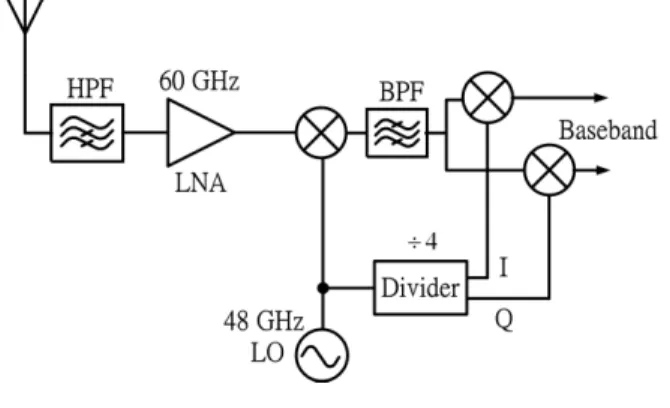
The double-conversion zero-IF 60-GHz receiver architecture, shown in Fig. 1, is proposed for the feasibility evaluation of the CMOS technology. The high-pass filter is placed in front of the LNA to reject the image signal of the first down-conversion. The frequency of the first-stage
local oscillator (LO) is 48 GHz and the IF is the 12-GHz signal. The IF signal goes through a band-pass filter to get rid of the harmonics and then feeds into the zero-IF converter. The quadrature LO signals of the direct down-converter can be obtained by dividing the first LO signal. The following sections will investigate the feasibility of the latest CMOS technology for every function block of the receiver, including the low noise amplifier (LNA), voltage-controlled oscillator (VCO), mixer, and frequency divider.
Fig. 1. The proposed CMOS 60-GHz receiver architecture.
2. CMOS Technology
One of the most major differences between silicon and III-V semiconductor technology is the lossy nature of the Si substrate. The resistivity of the Si substrate for a modern CMOS process is around 10 ͈-cm, whereas that of the III-V process is semi-insulating, 107~109͈-cm. The lossy Si substrate inevitably poses significant limitation on the performance of the CMOS devices. However, with the down-scaling the cutoff frequency fT and the maximum frequency of oscillation fmax are enhanced continuously. The transistor performance of the CMOS technology scaling from 0.25 Pm to 0.13 Pm is summarized in Table 1 [5]. The CMOS scaling improves both the speed and noise 0-7803-8865-8/05/$20.00 ©2005 IEEE. 92
figure of the transistors. The fmax of the 0.13-Pm CMOS technology has reached 90 GHz, and it suggests that some 60-GHz receiver building blocks can be demonstrated in the CMOS technology.
3. Front-end Function Blocks
3.1 Low Noise Amplifier
The LNA is the most challenging building block for the proposed receiver architecture because it must offer decent gain and low noise figure for the 60-GHz signal. The performance of the LNA is closely related to the sensitivity of the receiver. Although the 60-GHz CMOS LNA has not been reported yet, several CMOS LNAs operating beyond 20 GHz are demonstrated and summarized in Table 2 [6]-[8]. The operating frequency and gain of the 0.18 Pm CMOS LNA can achieve 26 GHz and 9 dB, respectively [6]. Since the fmax of the 0.13-Pm CMOS transistor is about twice that of the 0.18-Pm CMOS transistor, the LNA in 0.13-Pm CMOS technology, with proper design, should be able to deliver some gain at 60 GHz.
3.2. Mixer
The first mixer in the receiving path needs to translate
the 60-GHz signal to the 12-GHz IF signal with a 48-GHz LO source. Two CMOS mixers designed for down-converting the signals above 30 GHz have been reported [9]-[10]. Their performance is summarized in Table 3. One of the CMOS mixers is actually designed to convert the 60 GHz signal down to IF [10]. When the 0.13-Pm CMOS
mixer is driven by the 0-dBm LO signal, it’s IF and conversion loss are 2 GHz and 2 dB, respectively. The schematic of the quadrature balanced CMOS mixer is shown in Fig. 2. The direct-conversion mixers of the proposed receiver architecture don’t seem to be an issue for the latest CMOS technology because the input signals and LO sources that they deal with are 12 GHz.
Technology 0.25um 0.18um 0.13um
fT 30 GHz 45 GHz 105 GHz
fmax 20 GHz 35 GHz 90 GHz
Noise Figure
@ 2.4GHz 0.8 dB 0.6 dB 0.58 dB
Table 1. The fT, fmax, and noise figure of the CMOS
technology (0.25um-0.18um-0.13um) [5]. Ref. Technology CMOS fRF/fIF (GHz) GC [dB] PLO [dBm] [9] 90 nm SOI 35/2.5 -4.6 0 [10] 0.13 µm 60/2 -2 0
Table 3. Summary of CMOS mixers above 30 GHz.
3.3. Voltage-controlled Oscillator
Most of microwave VCOs are implemented in III-V or SiGe technology. However, with continuous scaling of CMOS technology, the fT and fmax have been high enough to demonstrate the VCOs oscillating above 40 GHz [11]-[15]. The schematic of the widely-used microwave CMOS VCO architecture is shown in Fig. 3. Accompanied by the high quality inductors, the CMOS VCO can achieve the low phase noise of -99 dBc/Hz at 1MHz offset from 50 GHz [11]. The push-push architecture can be used if the oscillating frequency is higher than the device fmax [13]. The 50-GHz fundamental frequency oscillator is also demonstrated in the standard 0.12-Pm CMOS technology [12]. The recently published CMOS VCOs oscillating above 40 GHz are summarized in Table 4. Therefore, the
Fig. 2. Schematic of the 60-GHz quadrature balanced CMOS mixer [10]. Ref. Technology CMOS fcenter GHz S21 [dB] NF [dB] Vdc (V) Idc mA [7] 0.18Pm 23.7 12.86 5.6 1.8 30 [6] 0.18Pm 25.7 8.9 6.9 1.8 30 [8] 90 nm SOI 40 9.5 4 2.4 17
Table 2. Summary of CMOS LNAs above 20GHz.
48-GHz first-stage local oscillator required in the proposed 60-GHz receiver, although difficult, is doable using the latest standard CMOS technology. The 12-GHz quadrature signal sources for zero-IF conversion can be obtained by feeding the 48-GHz LO signal to a divide-by-four frequency divider.
3.4. Frequency Divider
High speed frequency dividers are often implemented using current mode logic (CML), dynamic logic, or injection locking. The frequency divider working up to 100 GHz has been demonstrated in III-V and SiGe HBT technology [16]-[19]. Recently there have been efforts on developing CMOS frequency dividers for the signals above 40 GHz. A 40-GHz Miller divider of 2.5-GHz lock range is
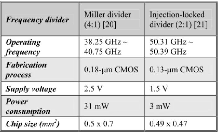
implemented in the 0.18-Pm CMOS technology [20]. Based on the injection locking architecture, the 0.13-Pm CMOS divider operates at 50 GHz and dissipates only 3mW [21]. The performance of these CMOS frequency dividers are summarized in Table 5. It can be inferred that the 48 GHz divide-by-four frequency divider is feasible in the 0.18/0.13-Pm CMOS technology.
fcenter GHz CMOS (Pm) Pnoise @1MHz (dBc/Hz) Tuning Range VDD (V) Power (mW) 50 [11] 0.25 modified substrate -99 2% 1.3 17 51 [12] 0.12 standard -85 1.4% 1 9.25 63 [13] 0.25
standard -85 1.6% N/A N/A
40 [14] 0.13 SOI -90 15% 1.5 17.25 43 [15] 0.13 standard -90 4.2% 1 14
Table. 4. Summary of CMOS VCO above 40 GHz.
Frequency divider Miller divider
(4:1) [20] Injection-locked divider (2:1) [21] Operating frequency 38.25 GHz ~ 40.75 GHz 50.31 GHz ~ 50.39 GHz Fabrication
process 0.18-µm CMOS 0.13-µm CMOS Supply voltage 2.5 V 1.5 V
Power
consumption 31 mW 3 mW Chip size (mm2) 0.5 x 0.7 0.49 x 0.47 Table 5. Summary of the CMOS frequency dividers above 40 GHz.
4. Conclusion
Fig. 3. Schematic of the popular cross-coupled CMOS VCOs.
The latest CMOS technology is evaluated for the 60- GHz wireless applications based on the double-conversion zero-IF receiver architecture. From the paper survey of the individual function block of the receiver and the scaling performance of the CMOS technology, it is very promising that 0.13-Pm or further down-sized CMOS technology is viable for the emerging 60-GHz wireless applications.
5. Acknowledgement
The authors would like to thank Taiwan National Science Council, National Chip Implementation Center, and UMC for the support of this work.
6. References
[1] Chris Koh, “The Benefits of 60 GHz Unlicensed Wireless
Communications,” Deployment White Papers, YDI
Wireless.
[2] K. Ohata, et al.,“1.25Gbps Wireless Gigabit Ethernet Link at 60 GHz-band,” in IEEE RFIC Symp. Tech. Dig., pp. 509-512, June 2003.
[3] C. Zelley, et al., “A 60 GHz Integrated Sub-harmonic receiver MMIC,” in IEEE GaAs IC Symp. Tech. Dig., pp. 175-178, November 2000.
[4] C. H. Doan, S. Emami, A. M. Niknejad, and R. W. Brodersen, "Design of CMOS for 60GHz applications," in
IEEE ISSCC Tech. Dig., pp. 440-538, February 2004.
[5] “Mixed Signal / RF CMOS,” UMC, http://www.umc.com. [6] Kyung-Wan Yu, Yin-Lung Lu, Da-Chiang Chan, Victor
Liang, and M. Frank Chang, "K-Band Low-Noise Amplifiers Using 0.18um CMOS technology," IEEE Microwave and
Wireless Components Lett., vol. 14, no. 3, pp. 106-108,
March 2004.
[7] K.-W. Yu, Y.-L. Lu, D. Huang, D.-C. Chang, V. Liang and M.F. Chang, "24 GHz Low-Noise Amplifier in 0.18um CMOS Technology," Electronics letters, vol. 39, no. 22, pp. 1559-1560, October 2003.
[8] Frank Ellinger, "26-42GHz SOI CMOS Low Noise Amplifier,” IEEE J. Solid-State Circuits, vol. 39, no. 3, pp. 522-528, March 2004.
[9] Frank Ellinger, Lucio Carlo Rodoni, Gion Sialm, Christian Kromer, George von Buren, Martin L. Schmatz, Christian Menolfi, Thomas Toifl, Thomas Morf, Marcel Kossel, and Heinz Jackel, “30–40-GHz Drain-Pumped Passive-Mixer MMIC Fabricated on VLSI SOI CMOS Technology,” IEEE
Transaction on Microwave Theory and Techniques, vol. 52,
no. 5, pp. 1382-1391, May 2004.
[10] Robert Brodersen, Ali M. Niknejad: "mmWave CMOS at BWRC: 60 GHz Transceiver Update,” Presented at
University of California Meeting, September 2003.
[11] HongMo Wang, “A 50GHz VCO in 0.25µm CMOS,” IEEE
ISSCC Tech. Dig., vol. 44, pp. 372-373, February 2001.
[12] M. Tiebout, H.D. Wohlmuth, W. Simburger, “A 1V 51 GHz fully-integrated VCO in 0.12µm CMOS,” IEEE ISSCC Tech.
Dig., vol. 1, pp. 300-468, Feb. 2002.
[13] Ren-Chieh Liu, Hong-Yeh Chang, Chi-Hsueh Wang, Huei Wang, ”A 63 GHz VCO Using a Standard 0.25µm CMOS
Process”, ISSCC Digest of Technical paper, pp. 446-453, Feb. 2004.
[14] Neric Fong, Jonghae Kim, J.-O. Plouchart, N. Zamdmer, Duixian Liu, L. Wagner, C. Plett, G. Tarr, “A low-voltage 40-GHz complementary VCO with 15% frequency tuning range in SOI CMOS technology,” IEEE Journal of
Solid-State Circuits, vol. 39, pp. 841-846, May 2004.
[15] A.P. van der Wel, S.L.J. Gierkink, R.C. Frye, V. Boccuzzi, B. Nauta, ”A Robust 43-GHz VCO in CMOS for OC-768 SONET Applications,” IEEE Journal of Solid-State Circuits, vol. 39, pp. 1159-1163, July 2004.
[16] A. Rylyakov, L. Klapproth, B. Jagannathan, G. Freeman, "100 GHz dynamic frequency divider in SiGe bipolar technology," Electronics Letters, vol. 39, no. 2, pp. 217-218, January 2003.
[17] A. Rylyakov, T. Zwick, "96 GHz static frequency divider in SiGe bipolar technology,” in IEEE GaAs IC Symp. Tech.
Dig., pp. 288-290, November 2003.
[18] M. Wurzer, T.F. Meister, K. Aufinger, J. Bock, S. Boguth, H. Schafer, "86 GHz static and 110 GHz dynamic frequency dividers in SiGe bipolar technology," IEEE IMS MTT-S Tech.
Dig., vol. 2, pp. 1067-1070, June 2003.
[19] S. Tsunashima, K. Murata, M. Ida, K. Kurishima, T. Kosugi, T. Enoki, H. Sugahara, "A 150-GHz dynamic frequency divider using InP/InGaAs DHBTs," in IEEE GaAs IC Symp.
Tech. Dig., pp. 284-287, November 2003.
[20] Jri Lee and Behzad Razavi, “A 40-Ghz Frequency divider in 0.18-µm CMOS Technology,” IEEE Journal of Solid-state
Circuits, vol. 39, no. 4, pp. 594-601, April 2004.
[21] Marc Tiebout, “A 50 GHz direct injection locked oscillator topology as low power frequency divider in 0.13 µm CMOS,” in European Solid-State Circuit Conf. Tech. Dig., pp. 73-76, September 2003.
![Fig. 2. Schematic of the 60-GHz quadrature balanced CMOS mixer [10]. Ref. Technology CMOS f centerGHz S 21 [dB] NF [dB] V dc (V) I dc mA [7] 0.18 Pm 23.7 12.86 5.6 1.8 30 [6] 0.18 Pm 25.7 8.9 6.9 1.8 30 [8] 90 nm SOI 40 9.5 4 2.4 17](https://thumb-ap.123doks.com/thumbv2/9libinfo/8848897.241435/2.918.86.441.818.935/schematic-quadrature-balanced-cmos-mixer-technology-cmos-centerghz.webp)