國 立 交 通 大 學
資訊科學與工程研究所
碩士論文
基於AFEC之嵌入式網路電話裝置語音品質控制機制
A Bandwidth-efficient AFEC-based Voice Quality Control
Mechanism for Embedded Systems
研 究 生:李開振
Student: Kai-Zhen Li
指導教授:黃育綸 博士
邵家健
博士
Advisor: Dr. Yu-Lun Huang
Dr. John Kar-kin Zao
基於AFEC之嵌入式網路電話裝置語音品質控制機制
A Bandwidth-efficient AFEC-based Voice Quality Control Mechanism for
Embedded Systems
研 究 生: 李開振 Student: Kai-Zhen Li 指導教授: 黃育綸 博士 Advisor: Dr. Yu-Lun Huang
邵家健 博士 Dr. John Kar-kin Zao
國 立 交 通 大 學 資訊科學與工程研究所
碩士論文
A Thesis
Submitted to Institutes of Computer Science and Engineering College of Computer Science
National Chiao Tung University in partial Fulfill of the Requirements
for the Degree of Master
in
Institutes of Computer Science and Engineering
July, 2009
Hsinchu, Taiwan, Republic of China
基於AFEC之嵌入式網路電話裝置語音品質控制機制
學生:李開振
指導教授:黃育綸 博士
邵家健 博士
國 立 交 通 大 學
資訊科學與工程研究所
碩士班
摘
要
隨著網路電話的蓬勃發展,近年來網路電話的聲音品質也逐漸變成眾所矚目的焦 點。 影響網路電話聲音品質的因素除了所使用的編碼方式之外,其還包括了網路狀 況,特別是封包遺失。 目前的研究有提出了一些如何來減少封包遺失對封包交換網路 的影響方法。 盡管這些方法在很多情況下表現都不錯,但並不是很適合使用於如網路 電話等高度即時互動的應用上。 因為網路電話的聲音品質除了封包遺失,還會被延遲 及抖動等因素所影響。 本論文提出一個可以用來探討封包遺失及錯誤修復等跟網路電 話聲音品質之間的關係的模型。 基於這個模型,我們設計出一個控制機制,可以在擁 擠的網路裡,增加最少的頻寬而有效提升網路電話的聲音品質。 我們所提出的機制建 構在自適應前向錯誤更正系統(AFEC)上,應用Reed Solomon Code來完成封包級的錯誤 修復, 而這樣的設計也更能符合真實的丟包情況。 為了可以實現在嵌入式系統上,我 們有對所需要的運算複雜度進行簡化。 我們把所提出的機制實作在一個有網路電話功 能的家庭路由器上,同時也完成了一系列的實驗。 透過分析實驗結果得知,在這個機A Bandwidth-efficient AFEC-based Voice Quality Control
Mechanism for Embedded Systems
Student: Kai-Zhen Li
Advisor: Dr. Yu-Lun Huang
Dr. John Kar-kin Zao
Institutes of Computer Science and Engineering
National Chiao Tung University
Abstract
As the massive deployment of packetized voice over the Internet, the voice quality has be-come an important topic in recent years. Besides the codec type, the voice quality can also be affected by network conditions, especially the network loss. To remedy this issue, many mecha-nisms were proposed to model or recover the loss in packet networks. Despite these mechamecha-nisms perform well in many cases, however, they are not suitable for real-time and interactive applica-tions such as VoIP, where the voice quality is sensitive not only to network loss, but also to jitter and end-to-end delay. In this thesis, we propose a model to address the quality of packetized voice under network loss and redundancy for loss recovery. Based on this model, we present a control mechanism to recover the voice quality of VoIP in a lossy network with less bandwidth overhead. Our mechanism is built on Adaptive Forward Error Correction (AFEC) with Reed-Solomon codes and performed at the packet level to better reflect the real world loss pattern. We try to reduce the computing complexity of our mechanism so that it can be easily realized on embedded systems. As a proof of our work, we implement the proposed mechanism on a home gateway with VoIP capability. We also perform some experiments to verify the effectiveness of our model. The experiments show that by using the proposed mechanism, under the loss ratio up to 30%, the voice quality can still be maintained above the designated threshold with the best bandwidth efficiency compared to the traditional AFEC mechanisms.
Acknowledgements
It is a pleasure to thank all the people who made this thesis possible.
I would like to thank my Advisors Dr. Yu-Lun Huang and Dr. John Kar-kin Zao, for their direction, assistance and guidance. And I would also like to thank all members of the committee. I wish to thank all professors who instructed me in each academic year. I must acknowledge Dr. Ho who gives me many suggestions and assistance in my studies. I would like to thank all members of RTES Lab for their support.
Finally, a special thank to my parents and family, without their love and encour-agement, I would not have finihsed this thesis.
Contents
摘要 i Abstract ii Acknowledgements iii Table of Contents iv List of Figures viList of Tables viii
Chapter 1 Introduction 1 1.1 Problem Description . . . 1 1.2 Contribution . . . 1 1.3 Synopsis . . . 2 Chapter 2 Background 3 2.1 Voice Over IP . . . 3
2.1.1 Session Initiation Protocol(SIP) . . . 4
2.1.2 Session Description Protocol (SDP) . . . 4
2.1.3 Real-time Transport Protocol (RTP) . . . 5
2.2 Voice Quality . . . 6
2.2.1 Factor . . . 6
2.2.2 Measurement . . . 8
2.3 Error Control . . . 9
2.3.2 Adaptive Forward Error Correction (AFEC) . . . 10
2.3.3 Reed Solomon Codes . . . 10
2.4 Related Work . . . 11
2.4.1 Interleaving Mechanism . . . 11
2.4.2 Feedback Control Mechanism . . . 12
Chapter 3 Proposed Mechanism 15 3.1 Framework . . . 15 3.2 Control Model . . . 16 3.3 Control Mechanism . . . 18 3.4 Algorithm . . . 22 Chapter 4 Implementation 24 4.1 Overview . . . 24 4.2 Sending Flow . . . 24 4.3 Receiveing Flow . . . 26 4.4 Coding . . . 27 4.5 Control . . . 28 Chapter 5 Experiments 31 5.1 Experiments Setup . . . 31 5.2 Configurations . . . 33
5.3 Results and Analysis . . . 34
List of Figures
2.1 The topology of a VoIP system . . . 3
2.2 The state diagram of Gilbert-Elliott Lost model . . . 8
2.3 The encoding and decoding of Forward Error Correction . . . 10
2.4 The technique of interleaving, repetition and interpolation . . . 12
2.5 The function J with fixed redundancy u and probability p . . . 13
2.6 The control structure for error correction . . . 14
3.1 The voice path in a VoIP application . . . 16
3.2 The voice path in a VoIP application with AFEC . . . 17
3.3 The voice quality surfaces of function v for the control mechanism . . . . 18
3.4 The control flow . . . 19
4.1 Overview of the Implementaion . . . 25
4.2 The sending flow of our control mechanism . . . 25
4.3 The format of an AFEC header . . . 26
4.4 The header of an AFEC packet . . . 26
4.5 The receiveing flow of our control mechanism . . . 26
4.6 The Encoding and Decoding Process . . . 29
5.1 The experiments environment . . . 31
5.2 The VoIP Gateway . . . 32
5.3 The virtual enterprise network appliance, STJ-100 . . . 33
5.4 The Digital Speech Level Analyser II . . . 34
5.5 The performance of AFEC type (6,1) . . . 36
5.7 The performance of AFEC type (4,3) . . . 37
5.8 The performance of AFEC type (3,4) . . . 38
5.9 The voice quality of with and without AFEC . . . 38
List of Tables
2.1 Comparison of packet loss models . . . 7
2.2 The scale of PESQ score . . . 9
3.1 The RS type and its redundancy level . . . 21
3.2 A control table for voice quality recovery . . . 21
4.1 Proportion of Data to Redundancy for each RS coding type . . . 28
4.2 The RS coding type and its (k, u) combinations . . . 28
5.1 Control table for selected the RS coding combinations . . . 34
Chapter 1
Introduction
Voice Over IP (VoIP) becomes an important communication tool in our daily life as it is growing rapidly. However, the voice quality of VoIP is always used to compare with the one of fixed-line telephone, public switched telephone network (PSTN). In this thesis we introduce a control model to address the voice quallity for VoIP with packet loss and loss recovery. We also proposed a control mechanism which can be used to optimize the voice quality in VoIP application under a lossy network.
1.1
Problem Description
VoIP provides a conversation session between two or more users. To get a good conversa-tional quality, some facts such as voice quality and delay are very sensitive. The voice quality may be degraded by many factors, and the packet loss is a significant one. How to decrease the effect of packet loss becomes an important topic to VoIP.
error correction and a control algorithm. The control table is a well designed table with many error correction combinations for recovery of voice quality, and it is used by the control algo-rithm, where the most suitable combinations for certain network condition is selected. We have implemented this mechanism on a home gateway with VoIP capability and performed some experiments.
1.3
Synopsis
The thesis is organized as follows. We review the Voice Over IP, voice quality, error control related to VoIP and some limitation of embedded system in Chapter 2. Then, we propose a control model and mechanism which can be used in embedded system for VoIP in Chapter 3. Chapter 4 describes the implementation of the proposed control mechanism, and the experiments and performance are shown in Chapter 5. In the end, Chapter 6 concludes this thesis.
Chapter 2
Background
2.1
Voice Over IP
Voice Over Internett Protocol (VoIP) is a technology where the voice data is transported over packet switched networks rather than the public switched telephone network (PSTN). VoIP system can be in different kinds of topology, a VoIP topology is shown in figure 2.1. A VoIP system contains two main subsystem, siganling and media stream. The former does create, modify and terminate a VoIP call. A well-known signaling protocl is Session Initiation Protocol (SIP). The media stream delivers voice between endpoints with Internet Protocol(IP).
2.1.1
Session Initiation Protocol(SIP)
The Session Initiation Protocol (SIP) is a widely used signaling protocol in VoIP. It can be use to create, modify and terminate the session between two or more endpoints. The origin specifications of SIP is designed by Henning Schulzrinne and Mark Handley starting in 1996. The first standard version of SIP is published in March 1999 as RFC2543 [2]. The latest version of SIP is defined in RFC3261 [3] which was published in June 2002. SIP is also accepted by The 3rd Generation Partnership Project(3GPP) as signaling protocol and permanent element of the IP Multimedia Subsystem (IMS).
2.1.2
Session Description Protocol (SDP)
The Session Description Protocol (SDP) describes the parameters for media of a session. It is in the ASCII string format . The original specifications of SDP was published in April 1998 as RFC2327[4], and a revised version was published in July 2006 as RFC4566[5]. Its purpose is to negotiate the parameters for media between endpoints. An SDP description includes 1) Session name and purpose; 2) Time(s) the session is active; 3) The media comprising the session and 4) Information needed to receive those media. SDP describes a session as a series of attributes type and value pairs. The attributes type and value is seperated by '=' in the form < type >=<
value >. The attributes type are only one case-significant character; The values can be an
ASCII string and its structure depends on the attributes type. The set of SDP attribute types is not intended to be extensible. The attribute type "a = " can be used to extend the SDP in the form a =< attribute > or a =< attribute >:< value >. A session description may have any number of "a = " attributes type.
2.1.3
Real-time Transport Protocol (RTP)
Real-time Transprot Protocol(RTP) is a transport protocol for real-time application. It pro-vides end-to-end network transport function for transmitting real-time data over internet, such audio, vedio. RTP also supports transfer data to multiple destination by using mulitcast. The specifications of RTP is published in January 1996 as RFC 1889 [6] and revised as RFC 3550 in July 2003 [7].
RTP does not provide any mechanism to guarantee the quality of service and delivery. It assumes that the underlying network is reliable. Typically, the application runs RTP on the top of User Datagram Protocol(UDP). However, RTP may also used on other suitable underlying network or transport protocols.
RTP Control Protocol (RTCP)
The RTP Control Protocol (RTCP) is a control protocol for RTP and it is sent periodically in a RTP session [7]. It provides the statistics and control information for the RTP session while the RTP delivers the media data. The same underlying protocol as RTP is used to transmit the RTCP with a defferent UDP port to RTP. They are two report froms for RTCP, the sender report (SR) and the receiver report (RR). The RTP receiver use the RTCP report to feedback the information. It may take one of the two forms depending upon whether or not it is also a sender.
2.2
Voice Quality
VoIP applications provides a real-time voice communication between two or more users. The voice quality of VoIP will directly affect the conversational quality as the poor voice quality will cause the inefficiency in communication [8].
2.2.1
Factor
There are many factors that affect the voice quality in VoIP and some of them are dalay, jitter and packet loss [9].
Delay
The transmission of voice data in network will introduce some delay. The mouth-to-ear dealy (MED) is used to measure the one-way qaulity of the conversation [8]. MED is the delay for transmission of voice from the mouth of speaker to the ear of listener. In a conversation be-tween VoIP users, they are talking and listening to each others. The talking and listening turns are switching between them. The delay impacts the switching frequency as they have to wait for more time in each turn. An MED of 300 milliseconds (ms) can significantly degrade the converesational quality [8].
Jitter
The voice data in VoIP application, RTP packes, are transmitted by packet switched net-work. The network with varying conditions will deliver the RTP packets with variable delay. The jitter is the variance of the RTP packets arrival time. Jitter degrades the voice quality as the
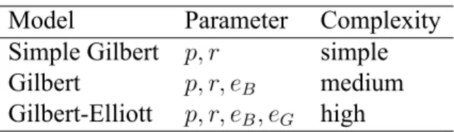
Table 2.1: Comparison of packet loss models Model Parameter Complexity Simple Gilbert p, r simple Gilbert p, r, eB medium
Gilbert-Elliott p, r, eB, eG high
listner can notice that there are delays in the speech. The jitter can be smoothed by using jitter buffer. The design of jitter buffer is out of the scope of this thesis.
Packet Loss
The packet loss occurs when the high congestion in the netowrk causes dropped packets. It could also occur for other reasons, for example occasional misrouting. The packets loss may take place in different pattern or timing, such as ramdomly loss, loss in burst or others. There are many models can be used to simulate the packet loss in a real network, and evaluating the equality of real time application is very sensitive to the loss model [10]. A 2-state Markov is introduced by Gilbert in 1960 [11] which is widely used to describe the loss pattern in trans-mission. This model was extended by Elloitt in 1963 [12]. Table 2.1 shows the comparison of Gilbert's and its models. The Gilbert-Elliott model is the most complex one and it is also the most suitable one for simulating the loss in real time service such as VoIP [13] [14].
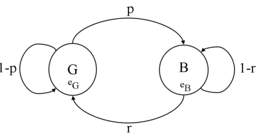
Figure 2.2 shows the state diagram of the Gilbert-Elliott model. p is the probability of the network state change from good to bad; While r is the probability of the network state change from bad to good. 1− p and 1 − r are the probability of the nework continue in good state and bad state, respectively. eBis the probability of a packet loss in bad state and eGis for good state.
Figure 2.2: The state diagram of Gilbert-Elliott Lost model
2.2.2
Measurement
There are many methods to measure and analyze the voice quality of VoIP [15]. All the testing methods can be classified into two types, subjective and objective tests.
Subjective test will be the most reliable approach to measure the voice quality because the test is carried out with the involvement of human listeners. The Mean Opinion Score (MOS, ITU-T P800) test [16] is the most and widely used method of subjective test. However, MOS is time consuming and expensive. Some other methods were also developed for measurement of voice quality.
In objective test, there are two methods, intrusive and non-intrusive. Intrusive methods compare the reference signals with the one been processed by network to produce a rating. Some widely used intrusive methods are Perceptual Analysis/Measurement System (PAMS), Perceptual Speech Quality Measure (PSQM) defined in ITU-T Rec. P.861 [17] and Perceptual Evaluation of Speech Quality (PESQ) defined in ITU-T Rec. P.862 [18]. PESQ is the successor
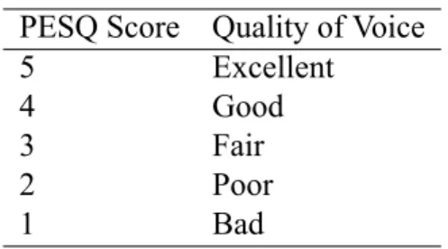
Table 2.2: The scale of PESQ score PESQ Score Quality of Voice
5 Excellent
4 Good
3 Fair
2 Poor
1 Bad
technology of PSQM and it employs to use true voice samples as test signals. The PESQ results are rated from 1 to 5 as shown in table 2.2. Non-intrusive method does not use the reference signal. It is based on the analysis of speech level, noise level and voice packet information. A well known non-intrusive method is E-model which is defined in ITU-T Rec. G.107 [19]. But without the use of reference signals non-intrusive methods are quite challenging [20].
2.3
Error Control
Error control for VoIP can be performed with either codec dependent or independent. For error control at the application level, codec independent method is recommended and it is also a reliable one [21]. Forward Error Correction (FEC) and Adaptive Forward Error Correction (AFEC) are widley used for error correction at the application level.
2.3.1
Forward Error Correction (FEC)
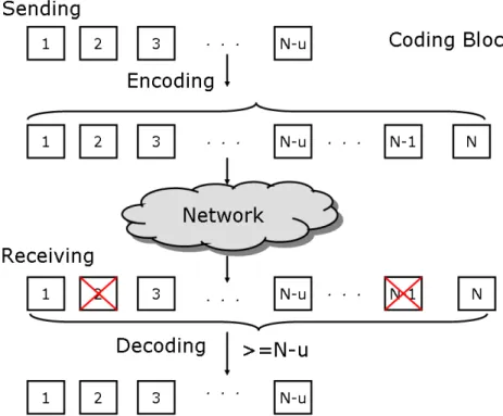
Forward Error Correction(FEC) is an error control system which can be use in data trans-mission [22]. In FEC system the sender encode the original data and transmit some redundant
Figure 2.3: The encoding and decoding of Forward Error Correction
of FEC depends on the degree of redundancy. The more redundancy, the high error correction rate. But Too many redundancy may waste bandwidth when the error rate is low.
2.3.2
Adaptive Forward Error Correction (AFEC)
Adaptive Forward Error Correction (AFEC) [1] is introduced to correct the error and use the bandwidth effectively. The error correction method of AFEC is the same as FEC. In AFEC system the recevier send feedback to the sender, so that the sender can adjust the degree of redundancy according to the current network conditions.
2.3.3
Reed Solomon Codes
Reed Solomon (RS) Codes were developed by Irving Reed and Gus Solomon in 1960 [24] and it is a widely used error correction code. RS codes are used in the data transmission, digital
communications, data storage and so on. RS codes are block codes and it is specified as RS(n, k) with m-bits data symbols and n = 2m− 1 are the total data symbols in a block. RS(n, k) means
the encoder takes k data symbols and makes n output symbols by adding n − k redundant symbols. The deocder can correct up to t errors or 2t erasures, where 2t = n− k. An erasure is an error where the position of the error is known.
2.4
Related Work
2.4.1
Interleaving Mechanism
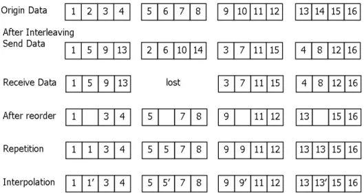
The interleaving mechanism is a technique which can be used to reduce the effects of lost packets[25]. The sender group the voice data packets into group and interleave the voice data in each packet of the same group. Figure 2.4 shows the interleaving of four packets in a group. The receiver has to reorder the interleaving data into the original sequence. This can distribute the effects of packet loss in burst. When there is a lost packet, the loss will be equally allocated into each packet of the same group. But there are still missing data in each packet. Some tech-niques, such as repetition and Interpolation are used to reproduce the missing voice data. The repetition reproduces the lost packets by repeating the last received packets; While interpola-tion reproduces the lost packet Piby the average the packets after and before, (Pi−1+Pi+1)/2.
1)End-to-Figure 2.4: The technique of interleaving, repetition and interpolation
2.4.2
Feedback Control Mechanism
A feedback control mechanism for error correction in packet-switched networks was pro-posed by O. Flardh et. al [26]. In their mechanism, an AFEC block contatins 0 ≤ ub ≤ N
redundancy packets and N − ub data packet. When there is packet loss, the lost packet can
be recovered if the received packets for the same block xb where xb ≥ N − ub. zb is an
recov-ery indicator, and 1 represents the recovrecov-ery success and 0 is failed. It can be expressed as below:
zb = 1 if xb ≥ N − ub 0 otherwise
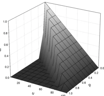
Figure 2.5: The function J with fixed redundancy u and probability p J (u) = 1 BN B ∑ b=1 E(N − ub)zb (2.1)
In this control mechanism there is a fuction J , equation (2.1). Its output is the probability of an AFEC block can be recovered successfully. It is influenced by the control of redundancy level
uband the probability of packet loss pb. Figure 2.5 shows the value of J with fixed redundancy
and probability of packet loss. We can see there is peak from (p = 0, u = 0) to (p = 1, u = 1). For different loss probability, there is a value of u which can give the highest J . The control function try to maintain the the J at the peak by adjust the redeuncy level u for different loss
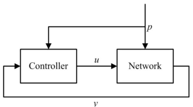
Figure 2.6: The control structure for error correction
unit is packet. The control of redundancy level in this mechanism is not very effective for VoIP, and the design of J doesn't consider the voice quality which is crucial to VoIP.
yb = (N − ub)zb (2.2)
Chapter 3
Proposed Mechanism
In this chapter, we propose a control model to address the voice quality with the packet loss and error correcction, and present a mechanism which can be used to maintain the voice quality above a designated level based on the proposed model. We describe about the framework of this model and followed by the control mechanism, coding for error correction and the algorithm.
3.1
Framework
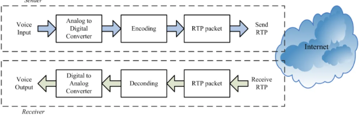
In a VoIP network, there are many kinds of interfaces. As shown in Figure 2.1, VoIP appli-cations can be used on different devices. However there is a common path, the voice processing path, for all of them. It is the flow of how the voice from the mouth of speaker is processed and transmitted to the ears of listener. Generally, in a conversation session over phone the caller and callee are speaking and listening to each other, so they are sender and also receiver of voice in the session. To this end, there are two identical voice processing paths in a VoIP application. Figure 3.1 shows a generic voice processing path of VoIP. It includes sending and receiving. At the sender, the voice is converted from analog signal into digital, and then the digital signal is coded with a specified codec. These coded digital voice data will be enclosed with RTP and sent
Figure 3.1: The voice path in a VoIP application
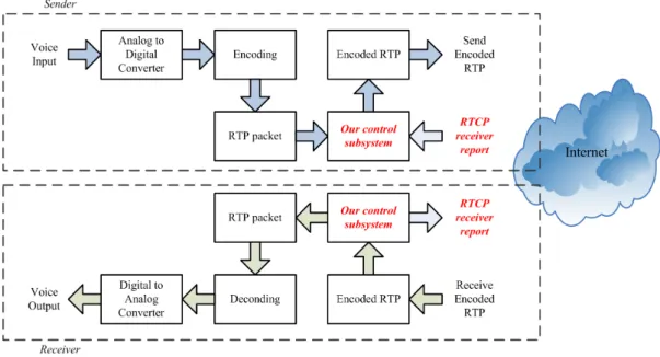
The voice quality of a VoIP application is affected by many factors. One key factor is packet loss which can degrade the voice quality significantly [27]. Adaptive Forward Error Correction (AFEC) is used to recover the lost voice data and it is also a good choice for VoIP [28]. In figure 3.2 an control subsystem with AFEC is added to the voice path of VoIP. When the voice quality control feature is enabled the VoIP application groups the RTP and encode them with error correction codes at the sender. These encoded RTP need to be decoded at the receiver. When the RTP is encoded some redundant data is added to the original data. The receiver use this redundant data to recover the lost data when there is packet loss. The more redundancy, the more loss data can be recovered. But too many redundancy may waste bandwidth when the packet loss rate is low or there is no loss. This control subsystem allows the VoIP application to adjust the redundancy level according to the network condition. But in order to let the sender adjust the redundancy level effectively, a good control mechanism is required.
3.2
Control Model
The proposed control model, Voice Quality Estimation (VQE) model v(u), can be used to address and optimize the voice quality for VoIP under a lossy network. This model is obtained from a series of test and analysis of the relation between voice quality and the packet loss and loss recovery. VQE model is expressed in equation (3.1), and it is very clearly to notice that the
Figure 3.2: The voice path in a VoIP application with AFEC
impairment of packet loss is deducted and the recovered advantage of AFEC is added. g is the original voice quality, when there is no packet loss; p is the independent probability of packet loss; u is the degree of the redundant data in an RS coding group; α and β are the coefficients of the recovered advantaged of error correction and the impairment of packet loss, respectively. Figure 3.3 shows the voice quality surface of the function v with fixed redundancy level and loss rate. In the figure we can see that the voice quality keeps in good state for no packet loss. When the packet loss rate increase, the voice quality will drop down significantly if there is no redundancy. If the redundancy level is increased as teh packet loss is increased, the voice quality can be maintained above a designated level.
Figure 3.3: The voice quality surfaces of function v for the control mechanism
u - the degree of the redundancy in an RS coding group.
α - the coefficient of the voice quality improved by error correction. β - the coefficient of the voice quality degraded by packe loss.
3.3
Control Mechanism
The control mechanism includes three components: control flow, coding method and con-trol table.
Control Flow
As we discussed before there are two identical voice processing path in a VoIP application, the sending and the receiving. So in the endpoint of VoIP, there are sender and receiver mod-ules. When the receiver decodes the incoming voice stream from network, RTP, it calculates
Figure 3.4: The control flow
the packte loss rate and recovery fail rate. The receiver module shares these information with the sender module in real time, and report them to the other end with RTCP receiver report. The sender module also receives the receiver report from the other end, and it can know the current network conditions from thes information. So the sender module can select the most suitable RS coding combination from the control table by using the algorithm 1 for the most effective error correction.
Coding Method
In our proposed mechanism, Reed Solomon codes (RS) [24] is used to implement the packet level error cocrrection for VoIP and RS codes are renowned for its excellent error correcting properties [21]. In RS coding the smallest data unit is a data symbol. For a data symbol has
n− 1 RS typefor error correction as shown in table 3.1 and the total RS coding combinations is
shown in equation (3.2). The different between each RS type is the maximum redundancy can be used in the RS coding group.
T otal RS combinations =
n−1
∑
k=1
n− k (3.2)
The process of encoding and decoding for error correction will consume a significant com-puting time. This is the AFEC delay. In order to maintain a good conversational quality, the MED delay should be controlled under about 350ms [8]. The MED delay includes the AFEC dalay, the transmission delay and the delay caused by jitter buffer. The AFEC delay can be expressed as equation (3.3). In embedded system, the computing power is limited. To minimize the AFEC dealy, the proposed mechanism pregenerate and store the polynomial and finite field which will be used for encoding and decoding in an RS coding table.
Ti = twi + tei+ tdi (3.3)
Ti- Total AFEC delay
twi - time for waiting voice data from DSP.
tei - time for encoding the voice data into an afec group.
Table 3.1: The RS type and its redundancy level
RS Type Data Packets k Minimum u Maximum u Number of (k, u) Combinations
1 1 1 n− 1 n− 1
2 2 1 n− 2 n− 2
3 3 1 n− 3 n− 3
. . . .
n− 1 n− 1 1 1 1
Table 3.2: A control table for voice quality recovery
RS coding combinations Redundancy level(%) Loss rate(%) Fail rate(%) (k, u)0 (k0u+u0 0) 0 < LR0 ≤ lr0 F R0 (k, u)1 (k1u+u1 1) lr0 < LR1 ≤ lr1 F R1 (k, u)2 (ku2 2+u2) lr1 < LR2 ≤ lr2 F R2 (k, u)3 (k3u+u3 3) lr2 < LR3 ≤ lr3 F R3 (k, u)4 (k4u+u4 4) lr3 < LR4 ≤ lr4 F R4 . . . . (k, u)t (ktu+ut t) lrt−1 < LRt≤ lrt F Rt Control Table
Based on the VQE model v(u) and the above RS coding combinations, we can design a control table which is used by the control algorithm. For a packet loss probability p′ and a des-ignated voice quality v, we can find a redundancy level u′ from equation (3.1), and there will be an RS coding combinations (k, u)i, where (ki−1ui−1+ui−1) < u
′
≤ ui
(ki+ui) and LRi−1 < p ′
≤ LRi.
Table 3.2 shows a sample control table. In the control table, the RS combinations from (k, u)0
to (k, u)tare sorted with their redundancy level from low to high. The loss rate in the table is the
maximum packet loss rate which can be covered by the RS coding combination. The fail rate is the maximum acceptable fail rate to maintain the voice qaulity above the designated level. Modifying the fail rate can adjust the designated level of voice quality, and a small fail rate
re-3.4
Algorithm
The algorithm used in the proposed mechanism is described in algorithm 1. It uses the cur-rent loss rate and recovery fail rate to select an RS coding combination for error correction. Line 1 - 3 initialize the algorithm with current loss rate, fail rate and current index. Line 4 and line 15 use current fail rate and decide or move down or up in the control table. For moving down in the table, line 5 - 11 use current loss rate to select a suitable entry. When it is at the end of the table and no entry was found, line 12 - 14 turn off error correction. For moving up in the table, line 16 - 22 use current loss rate to select a suitable entry. When it is at the begin of the table and no entry was found, line 23 - 25 select the first entry. Finally, line 27 set the current index to the selected entry. This algorithm can select the most suitable RS coding combination for maintaining the voice quality at the best situation for the current network condition.
Algorithm 1 Select RS coding
1: f r ⇐ Current F ail Rate
2: lr⇐ Current Loss Rate
3: i⇐ Current Index 4: if f r ≥ F Rithen
5: while !End of Control T able do
6: if LRi < lr ≤ LRi+1then
7: N ew Index⇐ i + 1 8: f ound⇐ 1 9: break 10: end if 11: end while 12: if f ound̸= 1 then
13: Turn off error correction
14: end if
15: else if f r < F Rithen
16: while !Begin of Control T able do
17: if LRi−1 < lr≤ LRi then 18: N ew Index⇐ i 19: f ound⇐ 1 20: break 21: end if 22: end while 23: if f ound̸= 1 then 24: N ew Index⇐ 0 25: end if 26: end if
Chapter 4
Implementation
This chapter describes the overview of the implementation, the sending and receiving flows and the coding method for error control.
4.1
Overview
The implementation is developed on a home gateway with VoIP capability where a linux platfrom is used. It is in the form of a new feature added to this gateway, and it can be divided into three parts. The first part is configuration and control, the second is sending and receiving and the last one encoding and decoding. Figure 4.1 shows the overveiw of the implementation. The confguration and control allow to enable or disable this new feature on the gateway. The details of sending/receving and encoding/decoding will be described in later section.
4.2
Sending Flow
In the sending task, figure 4.2, the voice frame from DSP will be buffered. Then they will be encoded, when it is enough to encode into an AFEC group according to selected RS coding type and combination. After encoding, they will be paketized and tagged with an AFEC header. These packets will be enqueued into the sending queue and sent to destination. The voice pack-ets are sent in the similar way as sending RTP and the different is AFEC header is used instead
Figure 4.1: Overview of the Implementaion
Figure 4.2: The sending flow of our control mechanism
Figure 4.3: The format of an AFEC header
Figure 4.4: The header of an AFEC packet
4.3
Receiveing Flow
When the encoded RTP packet is received at the destination, they will be buffered and classified the same group together. Details flow is shown in figure 4.5. The packets of the same AFEC group will be decoded, when the number of received packets is greater than or equal to the number of the data packets, where k≥ u. After decoding, the voice data in each RTP packet will be reconstructed and then they will be enqueued into a playing queue. A RTP control task will dequeue and paly them to DSP with a timing of the packet interval.
4.4
Coding
Reed Solomon codes are used to encode and decode the RTP packet in the implementation. In the encoder/decoder each data symbol has 8 data bits, M = 8. Each data symbol is equal to one byte. The total data symbols(N ) in a RS codeword is 255, N = 2M − 1. The data length
of the target RTP packet is 36 bytes, K = 36. According to N and K, the total packet(n) in each AFEC group is 7, n = N
K. There are 6 RS coding type as shown in table 4.2. The Galois
Field GF (2M) can be used for all RS coding type, and GF (x) = x8 + x4+ x3 +2 +1 is used
in the implementation of encoder/decoder. But the polynomial for each RS coding type are dif-ferent, because the numbers of data symbols and redundancy are not the same in each type. A RS coding table will be initialized when the application is started. In the table, the Galois Field of GF (2M) and the polynomial for each RS coding type are stored. They can be used when encode and decode the RTP packet.
There are 6 RS coding type in the implementation. The main different between each type is the ability of error correction. The error correction rate is direct proportional to the redundancy data. For an RS coding type with high error correction rate, the total data bytes(k) will be much smaller than the redundancy bytes(u), because the total data in each a RS codeword is equal to
k + u. By increasing redundancy (u) can get higher error correction rate, but it will decrease
data (k) at the same time. The amount of k indicate the data can be transmited and used in a RS codeword. Table 4.1 shows detail proportion of data to redundancy for each RS coding type.
Table 4.1: Proportion of Data to Redundancy for each RS coding type RS coding Type Bytes of Data(k) Bytes of Redundancy(u)
1 36 219 2 72 183 3 108 147 4 144 111 5 180 75 6 216 39
Table 4.2: The RS coding type and its (k, u) combinations RS coding type Possible combination (k, u) Total combinations
1 (1,1),(1,2),(1,3),(1,4),(1,5),(16) 6 2 (2,1),(2,2),(2,3),(2,4),(2,5) 5 3 (3,1),(3,2),(3,3),(3,4) 4 4 (4,1),(4,2),(4,3) 3 5 (5,1),(5,2) 2 6 (6,1) 1
decoder can work with different type of RS coding at the same time. This is achieved by adding a polynomial management process. When the application is started, the RS init process will generate the polynomial for each RS coding type and store them in a specific table, the RS coding table. Galois Field of GF (2M) will also generated and save in the RS coding table. When the encode/decode functions is called, RS coding type will be passed as a parameters. They will map to the correct polynomial in the table before it encode/decode the data as shown in figure 4.6.
4.5
Control
Different network loss conditions will effect the voice quality in a different degree. Al-though more redundancy can cover high loss rate, but too many redundancy will waste the bandwidth and too few redundancy will not result a good quality. The redundancy ratios of the RS coding combinations are listed in table 5.1. A control mechanism is important in choosing a suitable RS coding combination to get the best voice qualiy effectively. There are two main
Figure 4.6: The Encoding and Decoding Process
factors for the control mechanism, packet loss rate and fail rate of loss recovery. For a combi-nation (k, u), the decoding can be success only when the number of packets received is greater than or equal to k. The Reed Solomon codes can recover the number of packets lost less than or equal to u, because the maximum code distance is u+1 [30].
Loss Rate = T otal packets received T otal packets sent
F ail Rate = T he number groups f ailed in decoding T he total number of groups
and phone B, they send RTP to each other. When A got the statistics of loss rate and fail rate, it can also expect its RTP to B will also experience the same loss rate and fail rate. In the control flow, figure 3.4, there are two control signals which can change the RS coding combination to be used in next AFEC group. The first one from the reverver module, as soon as the recevier calculates the latest loss and fail information, it updates them to the sender module. Another one is the loss and fail information in the RTCP receiver report which was sent from the other end.
Chapter 5
Experiments
The experiments are carried out by using a real appliation and in a simulated network en-viroment. In this chapter, we will describe the setup of the experiments, configurations and results.
5.1
Experiments Setup
Figure 5.1 shows the environment setup of the experiments. The application is running on a home gateway with VoIP capability. A voice quality analyser, Digital Speech Level Analyser II, is used to evaluate the voice quality. A network simulator, STJ-100, is used to simulate loss pattern as in a real network.
Figure 5.2: The VoIP Gateway
Target platform
The hardware used in the experiments is a home gateway with VoIP capability, figure 5.2. It is integrated with a Broadcom SoC BCM96358 and Legerity voice solution chip Le88221. BCM96358 has a 800 DMIPS VIPER core, and its scalabe clock rates is up to 300MHz. It got an 8 timeslot PCM interface which can be used by the voice application. It is also include the ethernet physical interface for network communication. Le88221 is a dual-channel telephone lie interface device which can provide all the necessary voice interface functions from the high voltage telephone line to the DSP digital interface. BCM96358 and Le88221 are connected by the PCM interface and some control gpio. The DSP is running on BCM96358 and it sends and receives the voice frame through this PCM interface to and from Le88221.
Network Simulator
A virtual enterprise network appliance, 100, is used as the network simulator. STJ-100 is a product of Shunra Software Ltd.,USA. It can be used to simulate different packet loss patterns and network behaviors. However, it can also simulate the Gilbert-Elloitt loss model
Figure 5.3: The virtual enterprise network appliance, STJ-100
which is used in our experiments.
Voice Quality Analyser
The voice quality is measured with a tools called Digital Speech Level Analyser II (DSLA II)[31]. DSLAII is a product of Malden Electronic Ltd.,UK. It is a high quality speech per-formance measuring system. There is a batch processor which can be used to process a large number of speech signal without intervention. DSLAII generate the speech signal and evaluate the resultant signal after it has been processed by a network or network element.
5.2
Configurations
Figure 5.4: The Digital Speech Level Analyser II
Table 5.1: Control table for selected the RS coding combinations Loss rate Packet level RS coding Redundancy level Fail rate
1% (6,1) 14% 1% 2% (5,1) 17% 1% 3% (4,1) 20% 1% 5% (3,1) 25% 1% 7% (5,2) 28% 1% 9% (4,2) 33% 1% 12% (3,2) 40% 1% 15% (4,3) 43% 1% 17% (3,3) 50% 1% 20% (3,4) 57% 1% 25% (2,3) 60% 1% 30% (2,4) 67% 1% 35% (2,5) 71% 1%
experiments will be 180-295ms. An conversation over VoIP with this end-to-end delay can still get a good conversational quality [8].
5.3
Results and Analysis
Figure 5.5 shows the result of RS coding combination(6,1) for the packet loss rate from 1% to 30%. We can see that the voice quality can be kept around 3.9 for the packet loss less than
Table 5.2: The AFEC delay for each Combination
Packet level RS coding Wating(ms) Encoding(ms) Decoding(ms) Todal AFEC Delay(ms)
(6,1) 150 5 20 175 (5,1) 120 5 20 145 (4,1) 90 5 25 120 (3,1) 60 5 30 95 (5,2) 120 5 20 145 (4,2) 90 5 25 120 (3,2) 60 5 30 95 (4,3) 90 5 25 120 (3,3) 60 5 30 95 (3,4) 60 5 30 95 (2,3) 30 5 35 70 (2,4) 30 5 35 70
3%. When the loss is increased the voice quality with error correction will also be decreased and much slightly than the one without error correction. When the loss is higher than 8%, the voice quality with error correction will go under the one without error correction. In figure 5.6 the RS coding combination (5,2) is used. It can keep the voice quality around 3.9 for the packet loss is under 12%. In figure 5.7 and 5.8 the RS coding conbination (4,3) and (3,4) ared used, respectively. Each of them can keep maintain the voice quality around 3.9 for the loss is under 18% and 23%. From these natures we can sure higher redundancy level can keep a good voice quality in higher loss. But using higher redundancy level may waste the bandwidth if the loss is not too high.
After the control mechanism is introduced, the application can select the most suitable RS coding combination for different packet loss rate. Figure 5.9 shows the result of the proposed mechanism and the one without error correction. It is very clear to see that the voice qaulity can
Figure 5.5: The performance of AFEC type (6,1)
correction.
In figure 5.10 shows the voice quality of a VoIP call in a simulated network with Gilbert-Elliot model where p = 0.3, r = 0.7 and eB = 0.08. We can see that the voice quality can be
Figure 5.8: The performance of AFEC type (3,4)
Chapter 6
Conclusion and Future Work
In this thesis, we proposed a control model which can be used to address the voice quality of VoIP with packet loss and loss recovery. Based on this model we presented a control mechanism for VoIP to recover the voice quality under lossy network. In this control mechanism, the error correction is performed at packet level with Reed Solomon codes and a control table is intro-duced. The control table is used to select the RS coding for error correction, and the use of this table can reduce the computing complexity at runtime. We implemnted the proposed mechanism on a home gateway with VoIP capability and carried out some experiments. The results show that by using the proposed mechanism the voice quality can be maintained above the designated level under the packet loss rate up to 30%, and the bandwidth overhead is more efficient than the traditional AFEC mechanisms. As a next step, his mechanism can be extended to support more than one codec at the same time. This is a future work which can make the control mechanism more completed.
References
[1] K. Park and W. Wang, ``Afec: an adaptive forward error correction protocol for end-to-end transport of real-time traffic,'' in 7th International Conference on Computer
Communica-tions and Networks, 1998, pp. 196--205.
[2] M. Handley, H. Schulzrinne, E. Schooler, and J. Rosenberg, ``SIP: Session Initiation Protocol,'' RFC 2543 (Proposed Standard), Internet Engineering Task Force, Mar. 1999, obsoleted by RFCs 3261, 3262, 3263, 3264, 3265. [Online]. Available: http://www.ietf.org/rfc/rfc2543.txt
[3] J. Rosenberg, H. Schulzrinne, G. Camarillo, A. Johnston, J. Peterson, R. Sparks, M. Handley, and E. Schooler, ``SIP: Session Initiation Protocol,'' RFC 3261 (Proposed Standard), Internet Engineering Task Force, 2002, updated by RFCs 3265, 3853, 4320, 4916, 5393. [Online]. Available: http://www.ietf.org/rfc/rfc3261.txt
[4] M. Handley and V. Jacobson, ``SDP: Session Description Protocol,'' RFC 2327 (Proposed Standard), Internet Engineering Task Force, Apr. 1998, obsoleted by RFC 4566, updated by RFC 3266. [Online]. Available: http://www.ietf.org/rfc/rfc2327.txt
[5] M. Handley, V. Jacobson, and C. Perkins, ``SDP: Session Description Protocol,'' RFC 4566 (Proposed Standard), Internet Engineering Task Force, 2006. [Online]. Available:
Internet Engineering Task Force, Jan. 1996, obsoleted by RFC 3550. [Online]. Available: http://www.ietf.org/rfc/rfc1889.txt
[7] H. Schulzrinne, S. Casner, R. Frederick, and V. Jacobson, ``RTP: A Transport Protocol for Real-Time Applications,'' RFC 3550 (Standard), Internet Engineering Task Force, 2003, updated by RFC 5506. [Online]. Available: http://www.ietf.org/rfc/rfc3550.txt
[8] B. Sat and B. Wah, ``Analyzing voice quality in popular voip applications,'' in IEEE
Trans-actions on Multimedia, vol. 16, 2009, pp. 46 -- 59.
[9] M. Manousos, S. Apostolacos, I. Grammatikakis, D. Mexis, D. Kagklis, and E. Sykas, ``Voice-quality monitoring and control for voip,'' in Internet Computing, IEEE, vol. 9, July-Aug 2005, pp. 35 -- 42.
[10] N. Yoma, C. Busso, and I. Soto, ``Packet-loss modelling in ip networks with state-duration constraints,'' in IEEE Proceedings-Communications, vol. 152, Feb 2005, pp. 1 -- 5.
[11] E. N. Gilbert, ``Capacity of a burst-noise channel,'' in Bell System Technical Journal, Sep 1960, pp. 1253--1265.
[12] E. O. Elliott, ``Estimates of error rates for codes on burst-noise channel,'' in Bell System
Technical Journal, Sep 1963, pp. 1977--1997.
[13] G. Haslinger and O. Hohlfeld, ``The gilbert-elliott model for packet loss in real time ser-vices on the internet,'' in 14th GI/ITG Conference - Measurement, Modelling and
Evalu-tation of Computer and Communication Systems, 2008.
[14] O. Hohlfeld, R. Geib, and G. Hasslinger, ``Packet loss in real-time services: Markovian models generating qoe impairments,'' in 16th International Workshop on Quality of Service, June 2008, pp. 239 -- 248.
[15] L. Sun and E. Ifeachor, ``Voice quality prediction models and their application in voip networks,'' in IEEE Transactions on Multimedia, vol. 8, Aug 2006, pp. 809 -- 820.
[16] I.-T. R. P.800, ``Methods for subjective determination of transmission quality,'' 1996. [Online]. Available: http://www.itu.int/rec/T-REC-P.800/en
[17] I.-T. R. P.861, ``Objective quality measurement of telephone-band (300-3400 hz) speech codecs,'' 1998. [Online]. Available: http://www.itu.int/rec/T-REC-P.861/en
[18] I.-T. R. P.862, ``Perceptual evaluation of speech quality (pesq): An objective method for end-to-end speech quality assessment of narrow-band telephone networks and speech codecs,'' 2007. [Online]. Available: http://www.itu.int/rec/T-REC-P.862/en
[19] I.-T. R. G.107, ``The e-model, a computational model for use in transmission planning,'' 2005. [Online]. Available: http://www.itu.int/rec/T-REC-G.107/en
[20] L. Ding, A. Radwan, M. El-Hennawey, and R. Goubran, ``Performance study of objective voice quality measures in voip,'' in 12th IEEE Symposium on Computers and
Communi-cations, July 2007, pp. 197 -- 202.
[21] C. Perkins, O. Hodson, and V. Hardman, ``A survey of packet loss recovery techniques for streaming audio,'' in IEEE Transactions on Network, vol. 12, Sep 1998, pp. 40 -- 48.
[22] G. C. Clark and J. B. Cain, Error-Correction Coding for Digital Communications. Perseus Publishing, 1981.
[25] P. Mayorga, L. Besacier, R. Lamy, and J.-F. Serignat, ``Audio packet loss over ip and speech recognition,'' in IEEE Workshop on Automatic Speech Recognition and
Under-standing, 2003, pp. 607--612.
[26] O. Flardh, K. Johansson, and M. Johansson, ``A new feedback control mechanism for error correction in packet-switched networks,'' in 44th IEEE Conference on Decision and
Control 2005 and 2005 European Control Conference, Seville, Spain, 2005, pp. 488--493.
[27] L. Ding and R. Goubran, ``Assessment of effects of packet loss on speech quality in voip,'' in 2nd IEEE Internatioal Workshop on Haptic, Audio and Visual Environments and Their
Applications, 2003, pp. 49--54.
[28] P. Santos, R. Balbinot, J. Silveira, and F. Castello, ``Analysis of packet loss correction and concealment algorithms in robust voice over ip environments,'' in IEEE Pacific Rim
Conference on Communications, Computers and signal Processing, vol. 2, Aug 2003, pp.
824 -- 827.
[29] P. Karn, Reed-Solomon coding/decoding package v1.0. http://www.piclist.com/, 1996.
[30] R. E. Blahut, Theory and Practice of Error Control Codes. Addison-Wesley, 1983.
[31] Digital Speech Level Analyser User Guide. Malden Electronics Ltd, 2005. [Online]. Available: http://www.malden.co.uk/downloads/dslausrgd.pdf
[32] B. Ngamwongwattana, ``Effect of packetization on voip performance,'' in 5th
Interna-tional Conference on Electrical Engineering/Electronics, Computer, Telecommunications and Information Technology, ECTI-CON, May 2008, pp. 373 -- 376.